Podcasting since 2005! Listen to Latest SolderSmoke

Saturday, December 5, 2015

Alan W2AEW Hears me on 40 AM with his Drake 2B


Alan W2AEW writes: 

How appropriate! I was casually listening to 40m AM on my refurbished Drake 2B, and I hear the rotation get passed along to none-other than N2CQR - the man that got me excited about the 2B in the first place. FB 20 over signal in NJ, OM! I was able to grab the video camera quickly before you signed off.  Alan's video appears above.

73,
Alan W2AEW
Holy cow Alan,  THE RADIO GODS HAVE SPOKEN!  Clearly you need to get on 40 meter AM.  Maybe get a DX-60 or something.   In your video I spotted several items in your shack that are also in mine:  in addition to the 2B, I see  a Turner +2 transistorized microphone, and that little (very useful) RadioShack speaker. Glad you heard me OM -- thanks for the recording!
73 Bill

Friday, December 4, 2015

The Pleasures of AM, and The 807 (Truly a Bottle Worthy of the Gods)

Sometimes a message posted in the comments section of the blog is so good that it needs to be raised up and converted into a posting all its own.  Such is the case with a message that Rupert G6HVY sent us last month about AM and old rigs.  60 meters eh? Hmmm...

Rupert wrote:

It's always a pleasure to listen to AM QSOs, which hereabouts seem to be mostly on 80 and 60. I bought an FM board for my FT-101ZD with the intention of getting some 10m action, but now I think I'll leave the AM board in (you can't have both) for when I get the beast out of storage. AM, even AM that hasn't been optimised for beautiful audio, sounds so much nicer than SSB.

The other side of AM is to get old military rigs up and running, which is quite the opposite to the golden voice crowd. Another project waiting for time and energy here is an RCA-built Wireless Sets Number 19, which can put out ten watts or so of AM from its 807 (truly a bottle worthy of the gods) - and of course, there are infinite numbers of 50s and 60s vintage thermionic projects in the contemporary magazines. It would be particularly satisfying to find the original PSU for that, as it has two Dynamotors to convert the 24V DC supply to HT, with the transmitter one cutting in when the PTT (sorry, pressel switch) is hit. I say cutting, it actually runs up to speed over a couple of seconds, giving an original 19 Set a very distinctive slow fade-in at the start of an over. Hearing one of those crackling away on 5 MHz is utterly delicious.

Rupert, G6HVY

Thursday, December 3, 2015

Pete Juliano's Simple-Ceiver on Hack-A-Day Today!


Check it out!  Pete's awesome project -- and equally awesome documentation of the project -- is recognized this morning by Hack-A-Day! Congrats Pete!  

http://hackaday.com/2015/12/03/radio-receiver-build-log-and-more/ 

Wednesday, December 2, 2015

Colchester Mighty Mite


GM Bill,

So, I got round to making my Michigan Mighty Mite!

The crystal arrived almost safe and sound, thanks to the USPS’ mail crusher. Perhaps they think that because email and packets can be compressed they can do the same with parcels? (the photo really doesn’t do it justice - the orange area is a large dent…):


No 2 son, Cameron (12), got involved - The extremely neat tank coil is his handywork :


And so to the video: Not only does it oscillate on the correct frequency as shown here, it also has the added bonuses of oscillating around 21.5Mhz (which is the number my frequency counter gives - which caused a great deal of head-scratching on first smoke), and muting the FM broadcast receiver on 96.1MHz on the shelf 3 feet away!. The dummy load is the 3w metal film resistor suspended in mid air.


You might notice more resistors in the circuit itself than the diagram calls for. I chose to have 2 x  20K resistors in parallel to produce a single 10K resistance that could handle .6W. And the poor old 27R .3W resistor got really hot and discoloured before rapidly increasing its resistance ( !! ), so I used 4 (2 serial pairs in parallel) to handle the current. They still get hot, but survive. And the 2N2222a has a bulldog clip heatsink.

Please excuse the uncorrected error at the end of the CQ call!!

This is the second transmitter I have ever built - the other one is a 30m Hans Summers QRSS kit which you also get the ‘blame’ for :-)

Thank-you, Bill. Keep up the good work.

73’s de G7TAT, Colchester, England.


Tuesday, December 1, 2015

Pete's Simpleceiver is DONE! And it is a thing of beauty


Pete's Simpleceiver is a thing of beauty.  And it is done.  And people are already building it: Jim WA7HRG has one in the works.  Go to Pete's blog for more details, pictures, videos, LTSpice simulations etc.  http://n6qw.blogspot.com/  Congrats Pete! 


Sunday, November 29, 2015

A Very Unusual Explanation of AM and SSB -- What Do You Think?

Wow, I've never seen it presented this way.  Am I losing it or is this just completely wrong?   This comes from this web site:

http://www.dsprelated.com/showarticle/176.php


TRANSMITTED SSB SIGNALS
Before we illustrate SSB demodulation, it's useful to quickly review the nature of standard double-sideband amplitude modulation (AM) commercial broadcast transmissions that your car radio is designed to receive. In standard AM communication systems, an analog real-valued baseband input signal may have a spectral magnitude, for example, like that shown in Figure 2(a). Such a signal might well be a 4 kHz-wide audio output of a microphone having no spectral energy at DC (zero Hz). This baseband audio signal is multiplied, in the time domain, by a pure-tone carrier to generate what's called the modulated signal whose spectral magnitude content is given in Figure 2(b).
In this example the carrier frequency is 80 kHz, thus the transmitted AM signal contains pure-tone carrier spectral energy at ±80 kHz. The purpose of a remote AM receiver, then, is to demodulate that transmitted DSB AM signal and generate the baseband signal given in Figure 2(c). The analog demodulated audio signal could then be amplified and routed to a loudspeaker. We note at this point that the two transmitted sidebands, on either side of ±80 kHz, each contain the same audio information.
In an SSB communication system the baseband audio signal modulates a carrier, in what's called the "upper sideband" (USB) mode of transmission, such that the transmitted analog signal would have the spectrum shown in Figure 3(b). Notice in this scenario, the lower (upper) frequency edge of the baseband signal’s USB (LSB) has been translated in frequency so that it’s located at 80 kHz (-80 kHz). (The phasing method of SSB radio frequency (RF) generation is given in Appendix A.)
The purpose of a remote SSB receiver is to demodulate that transmitted SSB signal, generating the baseband audio signal given in Figure 3(c). The analog demodulated baseband signal can then be amplified and drive a loudspeaker.
In a "lower sideband" (LSB) mode of SSB transmission, the transmitted analog signal would have the spectrum shown in Figure 4(b). In this case, the upper (lower) frequency edge of the baseband signal’s LSB (USB) has been translated in frequency so that it’s located at 80 kHz (-80 kHz). The baseband signal in Figure 4(a) is real-valued, so the positive-frequency portion of its spectrum is the complex conjugate of the negative-frequency portion. Both sidebands contain the same information, and that's why LSB transmission and USB transmission communicate identical information.
And again, in the LSB mode of transmission, the remote receiver must demodulate that transmitted LSB SSB signal and generate the baseband audio signal given in Figure 4(c).

More on Light Beam Telephony


Hi Bill,

Reading about the Photophone and modulating the Sun experiments by G3ZPF reminded me of my own schooldays when as a final year physics project I think in 1970, I and another pupil built a light modulated telephone based on a design published in Practical Wireless of June 1970 by J. Thornton Lawrence. For the optical system it used a pair of spherical mirrors from old projection televisions. The detector was the expensive (for a school kid) OCP71 photo transistor, though we did also try ordinary less expensive OC71 transistors with the black paint scraped off with less success.
As David G3ZPF noted the problem with filament bulbs was the thermal inertia, and as I found it was also possible for the filament to mechanically resonate in the wooden box and start to howl. As we had never heard of, nor could have afforded an LED, we tried a Neon bulb run from an HT battery and modulated with a transformer in series with it. I recall coupling up a broadcast radio as the audio source playing "My Sweet Lord" by George Harrison and receiving it at the other end of the physics corridor very loud and clear on the audio amplifier on our light telephone receiver, much to the consternation and annoyance of the other teachers in the adjacent classrooms.

I found my black and white photo of the light telephone gear, complete with carbon telephone microphone that we used. It did work a fairly good distance in daylight outside across the school playground, not just the couple of feet shown. Also attached are photos of the original magazine cover and index, but regrettably not the article itself.

This was all before I got my ham ticket, but I already was a SWL and had been exposed to a wonderful ham, Tom GM3OWI (Oh Wild Indians) who visited the school and demonstrated all sorts of neat stuff like lighting a bulb from the output of a transmitter, and also voice modulating a klystron 3cm transmitter that the school had for doing electromagnetic radiation experiments, like polarisation, reflection etc.

Come to think of it, we got to play with a lot of stuff at school in those days which would never be allowed now, mercury, radioactive sources, alpha, beta and gamma, X-Ray and UV.  The museum in Edinburgh also had a science area with similar stuff you could play with, and get great shocks from the Van der Graff generator if you put your hand on the glass cabinet and touched the adjacent metal radiator!

Happy days!

73 David Anderson GM4JJJ

Saturday, November 28, 2015

Photophone! Modulating the Sun by G3ZPF (and Alexander Graham Bell, and Mr. A.C. Brown of London)


Yesterday David G3ZPF sent us another very interesting e-mail, this one about some very creative sunlight communication experimenting that he and his brother did many years ago.  It appears to me that David -- on his own -- came up with a version of Alexander Graham Bell's Photophone (pictured above). 

Wikipedia says that Bell's invention was the first ever wireless telephony device.   Bell credited Mr. A.C. Brown of London for the first demonstration of speech transmission by light (in 1878).  

Here is the Wikipedia article: https://en.wikipedia.org/wiki/Photophone 

I think young David's placement of the small mirror on the cone of the AF amplifier's loudspeaker was brilliant! 


Hello again Bill,

Just (literally) finished the book and a couple of surprises awaited me in the final chapters

SSDRA = $200 on Ebay
My flabber has never been so ghasted....and I have a lot of flabber. I will treat my copy with even more reverence now. Srtangely I hadn't heard about EMRFD so I'll need to look into that

Modulating light
Your story about using a laser pen in a receiver reminded me of my method of modulating light which I've never seen anyone else mention.

In the mid 60's my brother had an electronics constructor set for his birthday. After the initial fascination I probably played with it more than him. I remember reading about modulated light transmitters and (because this was before I was anywhere near getting a licence) I decided to build one. My brother was sufficiently curious to help.

We started with the receiver. I purchased an OCP71 and managed to find an old 12" headlight reflector from somewhere. The cork from a wine bottle fitted nicely into the hole at the centre, and the cork was easily drilled out to accommodate the photo-transistor.

My brother constructed the "high gain audio amplifier" project from his constructor kit and we put two legs of the photo transistor across the mic input. We were rewarded by a buzzing sound so loud our parents yelled at us from the other room. It took us a few seconds to realise we were 'receiving' the 50Hz signal off the ceiling light (the house lights were on). Waving the headlight reflector around confirmed this. I still recall the excitement we felt at our 'discovery'.

So far, so ordinary, but the TX side is where I wandered off into the outfield. Normally people modulated an incandescent bulb but this required a many watts of audio power & the 'inertia' of the filament could be a problem.

I cannot remember what prompted me to do this, but next day I pulled the speaker grill off my tiny little medium wave transistor radio and glued a small mirror (from my mothers old 'compact') to the cone of the loudspeaker.

Then we went outside into a field near our house. My brother went to the far end and I set up the lil radio on a camping stool. Moving it around until the sunlight reflected off the mirror hit the headlight reflector about 200 yards away.

Then I turned on the radio. Instantly my brother started jumping up and down excitedly. It worked. My 200mW AF amp was modulating the *SUN* !

All those guys on 160m with their 10w of AM...pah. I had GIGAwatts of power under my control :-)

Looking from the receive end it was possible to see the light from the mirror flickering & I guess the movement of the speaker cone did not move the mirror exactly in the plane of the reflected beam. The 'wobble' fooled the phototransistor into seeing an amplitude modulated beam.

The beauty of this was that only a tiny audio amp was needed. This made me wonder about such a system being used in undeveloped countries (ones with more sunshine) as a comms system, with batteries recharged by the sun.

For the UK I thought about using a slide projector to provide the illumination, instead of the sun. Again a very low power audio amp was all that was needed, and there were no 'inertia' issues to worry about it.

But I was soon to suffer a setback. A few days later the headlamp reflector, sitting on a desk in my bedroom, managed to find itself in a position to focus the suns rays onto the cork holding the photo-transistor. Cooking the transistor & setting fire to the cork. Luckily my mother smelt the burning cork before any collateral damage was caused but I had a face-chewing when I came home from school.

I'd long since forgotten about all this until reading the later chapters of your book.

regards

David G3ZPF


Friday, November 27, 2015

VK3YE's HB Superhet: Simplicity+Serendipity = Elegance


Simplicity + Serendipity = Elegance.  Indeed it does.   I would also point out that Peter's rig contains an admirable dose of ugliness (in the positive sense).  Thanks Peter!

Wednesday, November 25, 2015

Octalmania -- KG7TR's Amazing Thermatron Rigs


Grayson in Turkey alerted us to Mike's homebrew rigs:

Bill, Pete:  

Tuesday, November 24, 2015

M1GWZ's Knack Story: From Crystal Sets to BITXs


M1GWZ writes: "Just to establish my DIY radio credibility, here is a photo of my contest-winning crystal radio. Unpowered, it has logged commercial stations from Ireland to Russia, and from Northern Norway to Algeria. Excuse the mess in the background - the workshop is being re-organized!"


Carissimo Bill (I don't speak Italian. I'm just showing that I have read the book).
One of the benefits of early retirement after ten years in the electronics industry and twenty-five as a University academic is that one gets the chance to research one's interests and also have time to experiment with them. You correctly comment that you doubt you will have trouble occupying yourself in retirement - this is true, but be prepared for the frustration of not making as much progress as you would hope for! Chores still steal your time from you - and you have no excuse for avoiding them when you're retired.
I was recently alerted to the availability of your book via Kindle, but have only just got around to reading it (retirement...). It has been both a joy and a curse. Congratulations! It made fine reading in a couldn't-put-it-down way, but has also added several more items to my already-arm-length retirement project list. This, of course, is the price one pays for education and for evading the curse of boredom. As a radio ham friend of mine says with a sigh, "So many projects, so few lifetimes." As a result of reading your book, I am now pursuing satellite communication with my Yaesu handheld, and will put together a dedicated homebrew Yagi-plus-transceiver system in the New Year. The Baofeng two-bander handheld can now be had for £18 in the UK, so I can afford to dedicate one to the system permanently. Cheap technology to talk via satellites! So far, I have just been listening in - for the last three days.
I have been building radios and short wave listening since I was about nine years old.  If it wasn't for a schoolfriend's father and a crystal set, I might not be e-mailing you now. (They are still talking about killing off MW AM transmissions in the UK. Sad for kids building simple radios, but good news for European DX! Swings and roundabouts.  I'd like to give the Xtal Set Society www.midnightscience.com a mention - virtually all the recent crystal radio technology involved was discussed and developed on their forum. ) Upon graduating in 1980, I found a life without exams strange, so I took and passed my amateur radio licence exams as a way of learning more about electronics. Then life intervened (work, romance, microcomputers, marriage, job changes, son) and it was twenty years before I actually took out the licence. No Morse test so I was initially VHF / UHF only, but later the rules changed and I had a full (phone) licence. However, I only wanted to tinker about with handhelds when visiting friends in the USA (met via crystal radio forums on the internet), so my station consists only of a Yaesu VX-7R and a VX-2R (purchased at Dayton Hamvention) as a backup. I've never wanted to fork out the grand or so for an HF transceiver (although now I'm retired...), but I would like to reach out on 20 metres. Now, curse you, I realize that I have all the electronic parts to build a BITX SSB transceiver - and may have to do so. Another item on the project list...
Apart from amateur radio and DIY discrete-level DIY electronics, it turns out that we might have a couple more things in common. Through visiting the Dayton Hamvention, I now have many friends via the AMRAD club around Washington DC and have met quite a few hams from the Vienna and Loudon groups. I have attended Dayton for about the last fourteen years but circumstances change and we might now decamp to February's Hamcation in Orlando. Meanwhile, I live about four miles away from Kempton Park and have attended most of the rallies there, so there is a good chance that we two may at least have occupied the same room, albeit without actually meeting, on at least one occasion. It's a small, beautiful world.
Anyway, you're a busy man and I'm a verbose retiree, so I just wanted to thank you for the book and the inspiration it has given me to do more in ham radio. I also build DIY audio projects including (music) synthesizers, but at least I can use up a few more junkbox components before they're used to weigh down my coffin.

Regards,

Philip Miller Tate M1GWZ

Monday, November 23, 2015

G3ZPF's Knack Story: Debunking Tech Fairy Tales, Surviving Nixie Tubes and Ferric Oxide


Bill:

I'm finding the book very entertaining, and am currently about halfway
through it. Like you there were a few electronic 'fairy tales' that I
was suckered into and I was pleased to see your debunking of them. My
professional training was structural engineering so anything electronic
I picked up along the road, and was thus an easy mark for misdirection.

I still remember the first time I realized that teachers sometimes don't
understand what they're teaching, but just repeating what they were
told. At age 11 we were using a thin tube with a slug of mercury and was
told that at -273c the air under the mercury would have zero volume. I
knew it was BS, but was too young to know why. A decade later I worked
it out for myself, by accident really, and I still feel slightly
resentful about being misled. Turns out that -273c is a 'convenience'
(aka a fudge factor) which makes the combined gas law work :-p

The first electronic fairy tale I encountered was "the feed impedance of
a half-wave dipole is 72 ohms". Taught to me while studying for the UK
radio exam, and trotted out repeatedly in the RSGB magazine.

This magically mutated into 50 ohms when the Japanese rigs started to appear,
which made me a tad suspicious, and when my very young self finally
scraped enough cash together for the ARRL handbook I spotted the graph
showing variation of feed impedance with height.

I was devastated. I remember wondering why all the old guys at the club
(who I spent most Sunday mornings listening to on 160m AM as an SWL)
didn't know this.

In that instant I saw that all my hours of climbing up & down ladders;
cutting and pruning my very low dipoles to get 50ohms (bear in mind how
changeable and usually awful the UK weather is) had been utterly pointless.

From that point on I used doublets + open wire feeder. Up the ladders
just once and all tuning done in the shack in a comfy chair with a coffee
in one hand using a PROPER balanced ATU, not some shonky single ended
thing with a balun on the back.

Of course I found out about saturating balun cores the painful way (a
T200 core stays very hot for a very long time), and accidentally
discovered the current balun (which I called the idle-mans balun) at a
time when nobody distinguished between a voltage balun and a current one.

I took my inspiration from the 'coax round a ferrite ring' method of
stopping TV coax braid from conducting my RF into the TV. Fast forward
20 years and current baluns are the way to go. Its tough being a visionary.

I remember spending a weeks wages (back in the 70's) on a Fairchild
9H59DO prescaler chip for my TTL freq counter. Like you I hate chassis
bashing and the counter only went in a box after I'd had so many jolts
off the 150v rail to the nixie tubes I figured it was box-it or die :-)


The circuit of the counter was 'designed' by me lifting the simplest
version of each part of the circuit from dozens of peoples designs &
just hoping it worked. By the time I'd finished I had learned enough to
know I was lucky it did work....and what a mess spilled Ferric oxide
makes on a pale grey bedroom carpet.


When GQRP first started up a bunch of us locals used to have a 10m net.
Primarily for ragchews but also to give the newly licensed types at the
club their first ever CW QSO on air. We were all sufficiently enthused
to build a 2w xtal controlled 10m CW TX. Using a 2n3819 in the PA & 2w
meant the matching was easy to 50 ohms.


We were all within a few miles of each other so 599+, so one guy built a
half-watt version. Still 599.

I decided to go for it. Grabbed my sig genny off the shelf. It had a 50
ohm output. Lightbulb moment. Set it to 1microvolt outputans keyed the
aerial with it. 539 all round, albeit with some chirp and drift. Well, it
was a valve sig genny.

1uV across 50ohms is qrpppppp. Thats when I realised the million miles
per watt is no challenge at all when radiating extremely low powers over
short distances.

Might  be harder today though. Back then we could hear the receiver
noise floor on 10m. Not much chance of that now.

But I confess I was always far more interested in operating than
building. Never had the luxury of a workshop. Always tucked into the
corner of a bedroom. If I couldn't hold it in one hand and drill it with
the other it couldn't happen.

I remember hearing that Kennedy had been shot at the instant it
happened. I was on 20m listening to a pair of USA hams rag-chewing and
they both had the TV on. I rushed downstairs to tell my parents who told
me I was talking nonsense "or it would have been on the news". Took a
couple of hours for it to appear on our TV news.

I used to love chatting to the USA novices on 15m CW back in the late
70's. Some of those guys were real pros. You could hear them coming back
to your CQ while screwing the trimmers on their xtals to get co-channel.

I still treasure a letter I have from one youngster. It was his first
QSO outside the USA. He tells how his mom got so excited she ran into
the road telling all the neighbours her lad was talking to England.
.....yes the one in Europe :-)

Life seems a lot more cynical these days.

Even to this day I find the concept of my voice turning into electrons
which throw themselves into space and sometimes hit another piece of wire
in another country and reproduce my voice genuinely 'magical'. Sadly my
grandkids don't 'get it'. They're happy with Skype, facetime, and TXT.

The closest they came to interest was the eldest grandson (at age 10)
saying "grandad, can I have that telegraph key when you're dead?".
Sensing my surprise he added "I'm not interested in morse, but it looks
kinda cool". Now he's 20. Bought his first apartment, and his first BMW.
Making his way in the world and glued to his iPhone.

It would be kinda nice to get back onto 160m AM, but sadly the
electrical 'crud' levels in the UK are S9+ down there :-(

I spent 30 years in front of a TS930, which was able to produce proper
AM because where most rigs had one xtal filter it had pairs of them. You
slide the filters over one another to get narrower passbands for CW and
if you slide them past each other you can gget DSB or AM.

Thanks for taking the time to write your book. You've lived a very
varied and interesting life. I wrote a SciFi novel back in 1980 but at
that time there was only one scifi agent in the UK and she didnt like
it. Maybe I'll get it onto kindle one day.

I was expecting a lot of free time in retirement, but between the 3
grandkids and my 94 yr old mom I have less time than when I was working.
But despite the dodgy knees and eyesight its the best job ever :-)

Regards,

David  G3ZPF
www.g3zpf.raota.org
www.raota.org

Saturday, November 21, 2015

SolderSmoke Podcast 182: Bears! MMM Update, On Pete's Bench, 160 AM Dreams, MAILBAG


20151116_091050[1]
N6QW Selfie
SolderSmoke Podcast #182 is available


Travelogue:  In Shenandoah with BEARS!

Michigan Mighty Mite Update and a Generous Offer (with conditions).

BENCH REPORT:
-- Pete's Ten Tec Conversion using LTSpice
-- Pete's Simple-ceiver
-- My CB to 10 conversion plans

DREAMS OF 160 METER AM:   KB3SII, N2CQR, N6QW Building for Top Band

Raspberry Pi Nightmares

Homebrew to Homebrew (HB2HB) Contacts

Elser Mathes Cup -- We have some competition!

QST, "The Radio Art,"  and The Channelization of HF Bands

WA5BDU Nick Kennedy on QSO Today  Podcast

Ed Walker of "The Big Broadcast" was a ham:  N3HFT

MAILBAG:  A Letter from Turkey: Tubes and R-390s
Si5351:  G4GXO says give it a go!


Thursday, November 19, 2015

Listening UP for KIC 846


How's SETI's investigation of peculiar star KIC 846 2852 going? @EricCMack checks in https://t.co/4roQ7nbDk9


Since October 16, the SETI institute has been using its Allen Telescope Array to observe KIC 846 2852 over a wide range of radio frequencies (1 to 10 GHz), looking for any artificial signals. Keep in mind that this star system is relatively far, roughly 1400 light-years away. That's more distant than the Orion Nebula, and getting there (if you feel the need) would require a 23 million year ride in our fastest rocket. But more to the point, any signals detectable here on Earth would have to be exceptionally powerful.
We're continuing to analyze the data. In another week, our SETI team will once again observe KIC 846 2852 using some new receivers being affixed to the Allen Array - known as Antonio feeds - that will increase the sensitivity by a factor of two. Check this space.
Meanwhile, consider KIC 846 2852 as something suggestive of cosmic company, but no more than a suggestion.

Wednesday, November 18, 2015

Pete's Suggestion for My Next Rig

8 FET Class E Rig made by Steve, WA1QIX
 
 
OR THIS:
 
The Class E rig is very tempting.  But no way on the ebay!  Too much of an appliance -- it even looks like a refrigerator.

Tuesday, November 17, 2015

AM Madness: Just When You Thought It Couldn't Get any Cooler...


I pulled an old Eico 435 'scope out of retirement.  I hope to use it as a modulation monitor (any suggestions on easy ways to hook it up for this purpose?).  I really like the grey and aluminum look of this station.  I tried putting a DX-60 on the same bench, but the green of the "modern" Heathkit clashed with the serious-radio look of the DX-100 and HQ-100. Thanks again to Tim Sutton for the aluminum boxes -- I am temporarily using them as supports for the D-104 and the 'scope.  You see, I'm standing up when I modulate this gear.  Somehow it seems right.  Also, the transmissions on AM are so long that you can go back to your chair and rest (a lot!) between your transmissions.  When your turn comes, the few seconds it takes you to get to the rig provide the customary (and polite) "dragging of the feet" that allows others on the frequency to announce their presence.  Then comes what is perhaps the most fun part of this setup: the AWESOME KERCHUNK sound of the DX-100 going from receive to transmit.  As you can see, we pay a lot of attention to aesthetics and radio ergonomics here at SolderSmoke HQ.  That little blue recipe box holds my AM contact card file from the 1996-2000 period of operations from Northern Virginia.

I'm planning on doing a little work on the DX-100.   There is a standard set of mods to the audio amplifiers, mostly just changing some caps. And I need to find out why some of the crystals are not working -- I suspect dirty contacts.   I might also change the mic connector.  Looking ahead, Steve Silverman KB3SII (SolderSmoke Lex-pert), Pete Juliano N6QW and I have vague plans for an assault on 160 meter AM.  

Over the weekend this rig yielded a number of really FB contacts. Brett N2DTS in South Jersey was running an amazing homebrew station:


Sunday, November 15, 2015

And Now for Something Completely Different: Boatanchors! AM! Top Band!


Lately  I found myself looking for something different to get involved in.  Pete's conversion of his Ten-Tec commercial rig got me thinking about converting an old CB rig to 10 meter AM.  I'm still planning on doing this, but noodling on this project got me thinking about AM in general.  I had the DX-100 that John Zaruba K2ZA had given me (it was his dad's).  I had it paired up with an old HQ-100 that I'd picked up in the Dominican Republic 20 years ago. (Looking at the old manual for this receiver, I realized that there is another reason why I feel so connected to it:  it was built on West 34th St. in New York City, not far from where I was born.)   On Veterans Day (November 11) I connected these two old Boatanchor veterans  to my 40 meter dipole, rigged up a connector for my Astatic D-104, and fired up on 40 meter AM. 

I had a blast!  I found myself in contact with hams who are interested in the inner workings of their gear, guys who know which end of the soldering iron to grab.  The DX-100 got great reports -- people said it sounded nice. 

Sam K4NDY told me that his DX-100 had started out at 100 pounds, but that as time passed (and as he has gotten older) he noticed that it has somehow increased in weight!   

Bill K8DBN was running a DX-60 and (like me) an HQ-100 (you see, we're no longer in Yaesu-Icom-Kenwood land!)

Mike KC2KJ was running a DX-100 and a Drake 2B.  FB!

Steve W3DEF was on with his B&W 5100B.

Dave W3CRA was on from the Collins Radio Association.  He restores Collins gear.  When he told me the DX-100 sounded great, I knew that it really did.

Today I talked to Ed KA3PTX who has this really cool Boatanchor station:
And also today I had a great contact with Howard Mills W3HM, one of the greats in the world of radio restoration.  Another fellow on frequency asked me to makes some critical comments  on Howard's signal quality ("Does he have too much low frequency?") -- I refused, saying I was unworthy. (I did say that he sounded great -- he did.)

Anyway, I'm out of the rut. An added benefit is that this new (old) interest moves me even further away from microscopic SDR rigs, and closer than ever to the Hardware Defined, analog, discrete component, menu-free radio that I prefer.  Check out the full schematic of a DX-100 -- simplicity, clarity, beauty:  

I had been thinking vaguely about someday getting on 160 meters -- I've never used those frequencies.   Yesterday I noticed that both the HQ-100 and the DX-100 cover this band.  THE RADIO GODS HAVE SPOKEN!

Saturday, November 14, 2015

W2DLH's 20 meter Mighty Mite


N2CQR & N6QW,
 
I ran across a reference to the SolderSmoke book and read through it very quickly.  Through the book, I discovered the SolderSmoke podcast and have been enjoying every minute!
 
I just want to thank the two of you for the inspiration and new motivation I’ve found in a hobby I’ve loved for 25 years!  I’ve never tried homebrewing anything but that’s about to change.
 
It took me a while but we have oscillations on or about 14.060 MHz!
I adjusted the circuit to use resistor divider biasing of the 2N2219 and changes to the biasing and coil to accommodate the 20m crystal. Also the only cap I had that worked was a 10-50pF trimmer. Aside from my placing the crystal in the wrong point in the circuit because I wasn't paying attention, this Michigan Mighty Mite needed minimal tweeting. The antenna is a 50 ohm resistor which the KX3 heard very well with its attenuator in line. 
 
Now my problem is that I listen to SolderSmoke in the car and it's bad form to take notes and drive at the same time. Also, I find myself wanting to experiment with all of the ideas from the podcast at once...  If I build your LBS in modules, Pete, then I can experiment later and swap circuits to my hearts content.
 
One question for now...where is a good source of plentiful, inexpensive crystals?
 
Thanks again, guys!
 
Darryl Hambly, W2DLH
- - - - - - - -
Grid DM78pu
G-QRP 15014
QRP ARCI 15138
SKCC 10990
- - - - - - - -
http://www.qrz.com/db/W2DLH

Friday, November 13, 2015

Waco Mighty Mite Mojo!


Eric:  Wow, great news from Waco.  JOO indeed!  And I really liked the WAY you did it, liberating crystals and wire from old TVs.   That definitely adds mojo to the Waco M^3.  Bill
 
Hello Bill,
  My name is Eric Melling KD0OXY. I have, as of tonight, officially passed selection for the CLA. My Michigan Mighty Mite began oscillating tonight between 1830 and 1900 CST and I am ecstatic about it! My foray into home brewing began mid-2011 when I obtained my general class ham license (I took Technician and General at the same time taking advice from my late grandfather). The first radio I ever purchased was the Pixie II kit and boy was that frustrating. I meticulously assembled the kit and worked very hard to stuff the transceiver, volume control, options to use the on-board key or a straight key, and maybe an on-board speaker or phones.  But, to my chagrin, I was treated to the sweet wafting smell of the magic smoke long before ever getting on the air. I eventually did get on the air with my aforementioned grandfather's VHF/UHF HT and until recently, this has been the extent of my Ham career.
 
  But on the advent of my starting an MA in applied linguistics at a school in Dallas (hour and a half from home in Waco) and the rekindling of my electronics knack occurring near- simultaneously with my discovery of the SolderSmoke Podcast, I decided to give it another go. First, I got the old pixie kit to oscillate and then ripped it apart for parts to another project (non-radio). Then I procured a second Pixie kit from ebay and built that. It oscillated right away! Still no contacts; my CW is... improving.
 
  All this to say that I still had an itch that wanted scratching Enter: The Color Burst Liberation Army! Not only could I truly build something from scratch, I could follow my true calling and de oppresso liber some crystal. So I pulled some 30 (or so) gauge magnet wire from an old CRT. I had wound and rewound my coil three times (and unfortunately, the third one looks the worst) for 80m then 20m (far fewer turns) and back to 80m with N'JOO (No Joy of Oscillation) in any configuration. I am using a polyvaricon pulled form an old AM/FM transistor radio, the Mitsumi PVC-2FX which has 82 pF, 140 pF,  20 and  40 pF sections which I have wired in parallel giving me ~0-282 pF of range? And finally, I was using a MPS A42 NPN transistor. I had to run some resistors in parallel and some caps in series to get the right values, but I eventually got it all together and looking pretty smart on a 1" x 1.5" piece of perf board. Alas! Nothing!
 
  I was poking around at the circuit and realized that when I keyed the transmitter, the coil would get really hot right at the tap. I still don't know why that was, but I figured it was a good sign as it meant something was happening. I also was getting plenty of pops and clicks on the receiver. Anyway, to make a short story long, I decided that the dark mark under the transistor was a bad sign, found an NTE 123 and plugged it in instead. And oh what a wonderful day to hear the first warblings of my very first all scratch built transmitter hitting the airwaves! And here is the video: https://youtu.be/yq2M1ryMkII
  
  Probably more than you wanted to hear, but there it is. I do plan to build an SSB transceiver someday (hoping sooner than later). I feel you and Pete and your podcast have really set me out on the right foot! I hope to HB2HB with you soon!

  Sincerely,
    Eric KD0OXY

Thursday, November 12, 2015

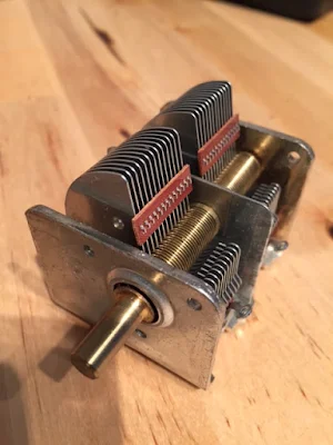
Psst... I know a guy with some caps.... Variable caps... Real beauties.... But only for Mighty Mites.


Feast your eyes my friends.   That is 400 micro-microfarads of variable capacitance.  (400 picofarads for you sophisticated young folks.)   A benefactor interested in expanding the ranks of the Color-Burst Liberation Army has stepped forward to make us an offer that is hard to resist:  He will send ELIGIBLE recipients one each of these fine electronic components for the cost of postage (approximately 6 bucks in the USA). 

He has specified that ELIGIBILITY is limited to those who need this part to build or complete a Michigan Mighty Mite.   And I have been appointed "Grand Poobah and Chief Arbiter of Capacitor Eligibility." 

So here is the deal:  Send me an e-mail telling me about your planned or stalled Michigan Mighty Mite project.  Include some information about your personal "Knack Story"  -- tell us why you share in this strange compulsion to build a largely useless 250 mW 3.579 MHz oscillator.   If I find your plans believable and your Knack Story compelling,  I will recommend you for a capacitor.  Purely aspirational MMM projects and obviously fabricated Knack Stories will not make the cut.

Supplies are limited, so act now! 

Wednesday, November 11, 2015

Stuart AC9LZ's Mighty Mite


FB Stuart!  Great work.  Pete is sending you info on a Low Pass filter that will clean up that harmonic-rich signal. 

Tuesday, November 10, 2015

Words of Wisdom for Homebrewers -- From Dave Metz, WA0AUQ


When you are done, be proud of what you have accomplished! Use it on the air and show it off to your friends an amaze them. Then clean the bench and start dreaming about your next project. 

Summary:
  • Decide if its important to do
  • Study the prior work of others
  • Make a preliminary simple design, document everything you do!
  • Round up your parts
  • Build in modules! Make one module at a time work.
  • Don't get discourage, ask questions, finish what you start
http://www.fpqrp.org/homebrew.html

There is a lot of tribal knowledge and homebrew wisdom in this link.  I tried to find a picture of OM Dave, but he has kept a low profile on the www.  The best I could come up with is a symbol of the club that he has been associated with.  Thanks Dave!

Here is the full document:
http://www.fpqrp.org/homebrew.html


Monday, November 9, 2015

Brazilian Minimalism: The Curruira Transmitter


Miguel PY2OHH is the Wizard of Sao Paulo. This morning I was looking at his wonderful web site and came across this little rig.  It seems a bit simpler than our beloved Michigan Mighty Mite.  And the folks down in Brazil had several of these on the air and made contacts with them.  FB.  Miguel hints they may turn this rig into a transceiver. 
Here is the Curruira:


The rig is named for this little bird: 


Sunday, November 8, 2015

Gregory Charvat HAS THE KNACK


Gregory Charvat N8ZRY

Yesterday I was talking to Allen W5SQK on 17.  He mentioned that he been working in his shop. You don't hear that too often these days, so naturally I asked what he was working on.  Turns out that OM Allen is building a coffee can radar!   He is enrolled in the MIT Lincoln Lab's Open Courseware Project (which looks very cool).  We had a great QSO, sharing tales of woe about the release of magic smoke from (dis)integrated circuits.  These are the things that pull us together my friends!
 
On the MIT page the name of a faculty member caught my eye: Dr. Gregory Charvat N8ZRY. Greg's rigs have been discussed on this blog at least twice, but it wasn't until today that I became aware of his many other interesting technical activities.  
 
Videos: 
 
 
Greg's KNACK STORY:


Saturday, November 7, 2015

Turkish Knack


Mehmet making contact using a homebrew rig

Lots of great homebrew videos from MehmetTB5X:
https://www.youtube.com/user/pashanline/videos

And he has a really nice web site:
http://www.tb5x.com/
Google Chrome does a pretty good job translating from Turkish.

Thursday, November 5, 2015

Nightmare Turns Real: "Rig Here is a Raspberry Pi OM, and I'm listening to you with my Dongle..."


As with many other nightmarish things, this one was launched at the world on Halloween. It all seems a bit flaky, but we knew this was coming.  Don't complain to me about the lack of low-pass filters, SSB testing on 7.000 MHz,  or the rather nebulous identity of the creator.... I'm just the messenger here.  And remember that I am a HARDWARE Defined Radio,  Discrete Component,  "Menus are for Restaurants" and (now) "Pi's are for eating" kind of ham. 
Here it is:
 

Designer: Douglas Bowman | Dimodifikasi oleh Abdul Munir Original Posting Rounders 3 Column