Podcasting since 2005! Listen to Latest SolderSmoke

Tuesday, February 21, 2012

New Oscilloscope!

That, my friends, is a genuine dual-trace, 100 MHz Tektronix oscilloscope. Wow, a new day has dawned on the N2CQR workbench! The 'scope comes to me as a result of the generosity of friend who, like the guy in the old "Millionaire" TV show, prefers to remain anonymous. He claims this is an equipment trade, but the terms were so one-sided (in my favor), that this was really a gift.

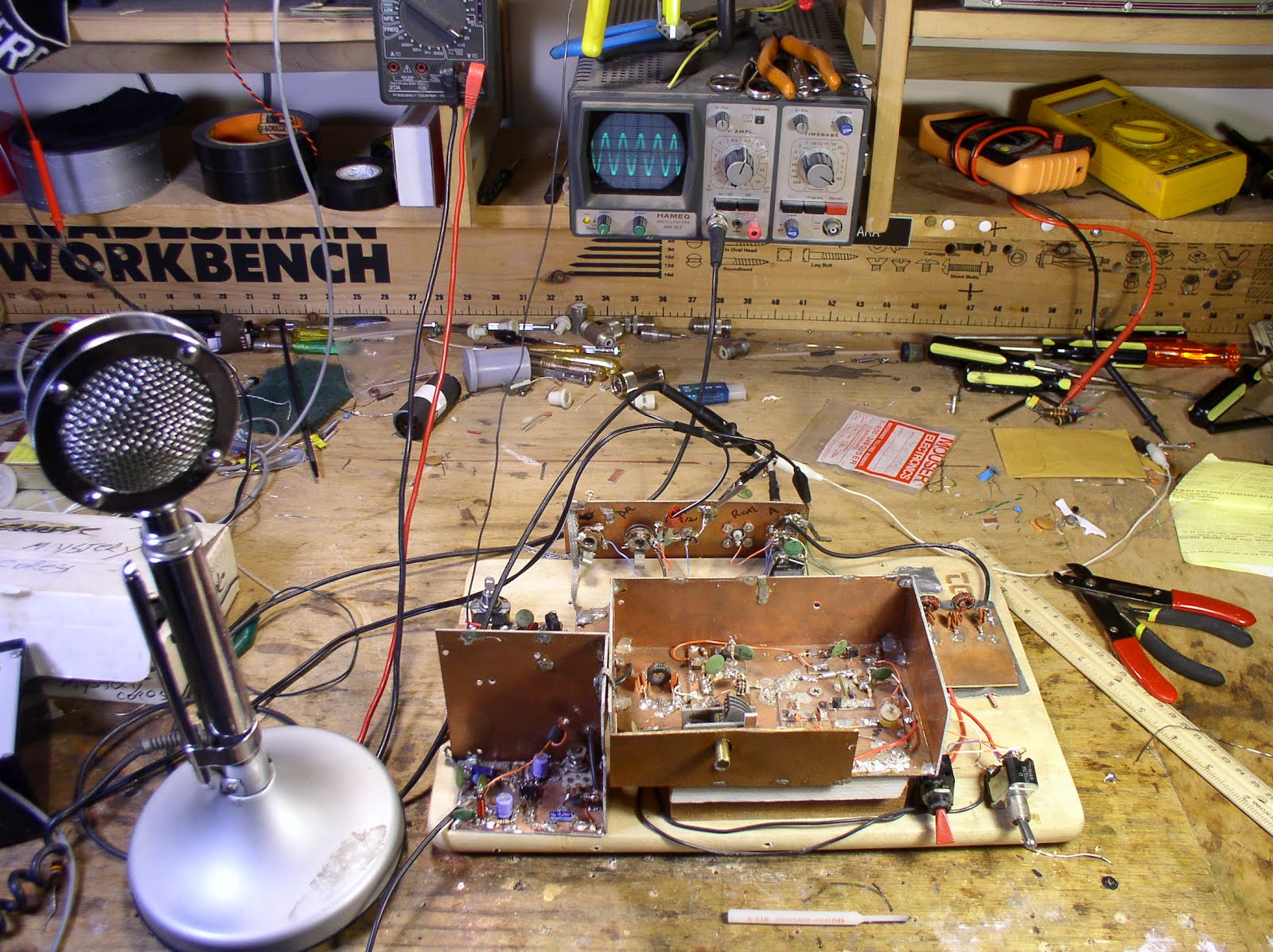
As you can see below, the 'scope fits perfectly in the center position on the shelf above the bench. I've already put it to work -- here you see it looking at the output from the VFO of the kick panel rig.


Our book: "SolderSmoke -- Global Adventures in Wireless Electronics"http://soldersmoke.com/book.htmOur coffee mugs, T-Shirts, bumper stickers: http://www.cafepress.com/SolderSmokeOur Book Store: http://astore.amazon.com/contracross-20

Book Sale!

Our book: "SolderSmoke -- Global Adventures in Wireless Electronics"
http://soldersmoke.com/book.htm

A Soldering Tip(!) from Australia

Ray notes that it should be mm not cm


Bill,

I heard you discussing the gadgets that you have in your shack on a recent SolderSmoke podcast particularly the small flame device that you use to remove the enamel from copper wire. I have found the following to be a fantastic way to remove the enamel and tin the wire at the same time. I was alerted to this process by Grant, VK4JAZ, who saw it on the Hendricks QRP Kits site.

Get hold of a basic soldering iron, usually around $10 - $20, and take out the solder tip (you don't need to buy a new iron if you have a spare tip but I find the separate iron allows me more flexibility during construction). Drill a hole in the base of the tip, about 5 - 10 mm, and place the tip point first into the soldering iron. The hole can be filled with solder when the iron is hot and all you do is put the enameled wire into the solder. The heat removes the enamel and the wire is tinned at the same time. The burnt enamel floats to the surface and all you need to do is skim it off before tinning another wire: Simple and neat.

Vy --... ...--,

de Ray VK4ZW

Our book: "SolderSmoke -- Global Adventures in Wireless Electronics"http://soldersmoke.com/book.htmOur coffee mugs, T-Shirts, bumper stickers: http://www.cafepress.com/SolderSmokeOur Book Store: http://astore.amazon.com/contracross-20

Sunday, February 19, 2012

Words of Wisdom from Farhan

I read the mail of the BITX20 group. Here is some good advice from Farhan:

I have often seen builders finishing an entire build, then powering it
up to face the frustration of a dead circuit. I suspect that the
trouble is with our kit building mind set. As a kit builder, we assume
that if it has worked well for a few hundred others, there is no
reason for it to not work for us. But the truth is more sobering ...
Of the hundred odd components, any of them could get swapped by
another, or a bad solder, wrong polarity, etc. can all conspire to
thwart your attempts. The bitx manuals are really some of the best
produced in the recent years and yet, even with leonard's videos,
troubleshooting kits is a challenge.
I am proposing a more elaborate, slower but surer approach to building the bitx.

It is as follows: build it one stage at a time, use one stage to test
the next. For instance, one could start with the bfo first. Just a
single transistor with the crystal. Then use an RF probe to check the
rf output. If there is no output, then sort that out before proceeding
to the next stage. With the addition of the buffer amp, the output
should go up. Then one could proceed to the audio amp. Injecting audio
from your mp3 player or computer could check that it works. Next,
replace the audio source with the mic amp, this tests the mic amp.
Now, if you add the two diode modulator, you should be able to receive
the dsb at 10 MHz on your HF transceiver.

This approach tests each stage individually and in isolation before
proceeding to the next. It also provides wholesome education to the
builder. In software industry, it is called a 'test driven
development' method of developing software.

In the end, this approach is no slower than the current approach,
except that surprises are not kept for the last.

I am sure that some of us can come out with a sequence of stages to
build where each stage is tested using the previous stage.

As much as bitx is about building it cheap, it is also about learning
your radio from inside. Bitx is also education on the cheap, don't
give up that opportunity.

- farhan VU2ESE

Our book: "SolderSmoke -- Global Adventures in Wireless Electronics"http://soldersmoke.com/book.htmOur coffee mugs, T-Shirts, bumper stickers: http://www.cafepress.com/SolderSmokeOur Book Store: http://astore.amazon.com/contracross-20

Kick Panel Rig: EXPOSED!

There it is, sans kick panel. You can see the breadboard (a real one!) on which it is built. The box in the center has the oscillator circuitry (currently on 75 meters, but subject to change); the box is elevated a few inches by two pieces of wood -- I do this so that the frequency control will be a comfortable distance from the table! HB-ergonomics! The AF (mic) amp is in the lower left (just a 741 op amp). You can see the adjustment pot of the balanced modulator behind the mic amp. The low pass filter of the PA is visible on the right (rest easy Steve Smith!). The switch on the right is T/R. The red switch is "spot" (or in the UK "net").

I thought I was having some trouble with RF getting into the mic amp. The audio out from the mic amp looks a bit distored when I have the oscillator and PA circuits fired up. I worked on it for a while, beefing up the decoupling on the 12 volt lines, but that didn't change things. I've decided not to worry about it, because the output signal from the final looks clean, and the signal sounds good on my trusty Drake 2-B. It may have been a test gear problem -- the 'scope probe may have been picking up some RF and may have been uglying up the AF wave form.

Our book: "SolderSmoke -- Global Adventures in Wireless Electronics"http://soldersmoke.com/book.htmOur coffee mugs, T-Shirts, bumper stickers: http://www.cafepress.com/SolderSmokeOur Book Store: http://astore.amazon.com/contracross-20

Wednesday, February 15, 2012

Kickin' the Kick Panel to 40?

Thanks for all the suggestions re what to do with the kick panel rig. Steve "Snort Rosin" Smith (pictured above) suggested getting a 9 Mhz crystal filter and building an SSB rig for 75 and 20 meters. I was tempted Steve, but remember, simplicity is a virtue, and DSB makes a transceiver REAL simple.

Craig and OM KWJ suggested 10 meters. I hear you, but I'm looking for a rig that I can use for pre-dawn rag chews, and at that hour 10 is often a white noise generator.

Bruce wants me to put it on 475 KILO hertz. I dunno about that one Bruce -- sounds kind of lonely!


As I thought this over, I remembered a comment from the true guru of DSB: Peter, VK3YE. In one of his inspiring videos, he mentioned that 40 meters is his favorite band for DSB rigs. It is 0545 local and I am hearing a lot of activity on 40. It all sounds very friendly. Some DX coming through... I could make a stable VFO for 40. Then I add a little DC receiver and I'm in business. So I'm leaning towards 40 meters at this point.


Our book: "SolderSmoke -- Global Adventures in Wireless Electronics"http://soldersmoke.com/book.htmOur coffee mugs, T-Shirts, bumper stickers: http://www.cafepress.com/SolderSmokeOur Book Store: http://astore.amazon.com/contracross-20

Tuesday, February 14, 2012

Back to the "Kick Panel" DSB Rig

OK, so now that the 17 meter rigs are fully operational, I am turning my attention to another homebrew rig from days gone by: This is what I call my "kick panel" DSB transmitter. You see, the metal cabinet is made from a piece of metal intended for placement on the bottom part of a door -- so that people (in a pub, I suppose) won't wear out the door with their feet. I built this rig in my attic shack in London. The breadboard on which it is built is from a Dyas store in Windsor, England. The top of the box comes from a computer I found discarded on the mean streets of South Kensington. I think I originally built this thing for 40 meters, but later switched the VFO and the low pass filter to 80 meters. This rig is discussed in the opening pages of the London chapter of "SolderSmoke -- Global Adventures in Wireless Electronics."

The oscillator is running as it should and the RF amplifier chain (my design) is amplifying (and not oscillating!). The balanced modulator is doing its balancing act quite nicely. The only problem seems to be with the the little op-amp that have in there for the AF -- it seems to be distorting the audio quite a bit. That shouldn't be hard to fix.

There is room in the box for a simple Direct Conversion receiver, so this box will become a DSB/DC transceiver.

But here is my problem: I find myself unenthusiastic about working on a rig for 75 or 80 meters. On the one hand those frequencies are good for me -- I'm an early riser and I need a rig that I can use in the hours before sunrise. But 75/80 always seems to be an unfriendly place -- lots of frequencies that seem to be "claimed" by groups who don' t seem interested in meeting newcomers, not a lot of people calling CQ...

I can put this rig on another HF band. 40 seems nice, but I have plenty of old boatanchor stuff that covers 40. I don't need another 17 meter rig. I already have a homebrew 20 meter DSB rig. How about 12 meters? Or 10? I know they are both dead in the early morning, but better times are coming, right? What do you guys think? To what band should I kick the kick panel rig?


Our book: "SolderSmoke -- Global Adventures in Wireless Electronics"http://soldersmoke.com/book.htmOur coffee mugs, T-Shirts, bumper stickers: http://www.cafepress.com/SolderSmokeOur Book Store: http://astore.amazon.com/contracross-20
Designer: Douglas Bowman | Dimodifikasi oleh Abdul Munir Original Posting Rounders 3 Column