Podcasting since 2005! Listen to Latest SolderSmoke

Monday, August 17, 2009

Pico-Sats, Texas, Dubai, Balloons


Our man in Dubai, Ron Sparks, AG5RS, sent in this very interesting report on the very small satellites. Obviously lots of QRP relevance here:

Hi Bill,

I am attaching some news you may find interesting. If you remember last year I did an echolink => IRLP => 2m linkup to make QSLs on the Balloon Launch (BLT-24). Besides the usual repeater and video gear, we also had an interesting "hitchhiker" on the payload.

It was the functional engineering model of the BEVO-1 picosat. You can see pictures of the model and the balloon payload here:

http://www.w5acm.net/b24.html

This unit sent beacon information during the balloon launch and we tested it environmentally by doing so. Data on the sat itself is at:

http://www.utexas.edu/news/2009/06/09/picosatellite/

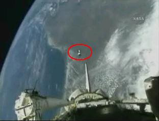
A sister satellite was being prepared by my alma mater, Texas A&M, who then docked their sat with the UT sat and put them on the Shuttle mission STS-127. Photos are here:

http://www.ne.jp/asahi/hamradio/je9pel/dragonst.htm

All of this is part of NASAs DRAGONsat program. This is a new GPS system being developed by NASA.

I know that the satellite stuff is a little "far afield" for Soldersmoke, but you might find the connection to the Houston balloon community interesting. Those of us who get together and annually launch the balloon are without question Soldersmoke-ers with chronic cases of "the knack". It is fun for me to see that actually be useful toward a next generation replacement for GPS satellites.

All the best.
73 from Dubai, Ron AG5RS and A65BQ

Sunday, August 16, 2009

Back to WSPRing

Mark, K6HX, and Roger, G3XBM, are responsible for me going back to WSPR mode. Both have been blogging about the fun they are having with this mode. It was too hot in Rome to go out this afternoon, so, after a morning visit to the Trastevere flea market (where I got a US Robotics dial-up modem for my soon-to-be functional Satellite Pro computer (thanks Jeff!), I ensconced myself in the shack, and did the changeover from visual MEPT to WSPR. This mode provides instant gratification: almost immediately I was being picked up and reported by EI7GL.

Thursday, August 13, 2009

SolderSmoke (The Book) Reaches the Oregon Coast

Wes, W7ZOI, took the book with him on vacation and sent along this shot from the Oregon coast. I told Wes that I was really nervous when I saw his e-mail in my in-box. The book has sections about my "understandings" of various aspects of electronic theory. I worried that the e-mail would reveal that these were all "MIS-understandings." I was very relieved that wasn't the case! Wes provided an interesting bit of ham radio history/trivia: Around page 169, I have the iconic picture of Wes out in the winter woods somewhere, with a homebrew QRP rig in his hands. I remember seeing this picture as a kid. I found it inspirational: a stoic homebrewer, using his invention to communicate from out in the hostile wilderness. In his e-mail, Wes tells me that in that photo, he was actually in contact with another station. It was Lionel, VE6WG, up near Calgary. This photo was taken by K7IUN. Thanks Wes!

Wednesday, August 12, 2009

VE7NSD: The Knack, personified

We've occasionally provided photos that seem to capture the essence of "The Knack." Here is another one. This is Stephen, VE7NSD, operating from his trailer out in the wilds of British Columbia. I found Stephen's story to be really inspirational. His first receiver was a Gillette Blue Blade! His first QSO was with Beaverton, Oregon! He took typing in 9th grade (the only boy in the class!) so that he could copy CW faster. Here is an excerpt from his QRZ.com page:

I started playing with radios in Roseburg, Oregon when I was ten. My Dad’s prospecting buddy Cliff, had been a Radioman in the USN and turned me on to building a crystal set using a Gillette Blue Blade for the detector. I built it but had no headphones and ordered some from the Allied Radio catalog. I felt like it took about 6 years for them to arrive, but it was probably more like 6 weeks. When the headphones finally came the xtal set didn’t work and so I started learning troubleshooting. Eventually, it worked fine and I experimented with a hunk of galena my Dad had in his rock collection.

From there Cliff gave me circuits for regenerative receivers and I built a few but none of them ever produced a usable output. All of my SWL listening had to be on the big console radio in our living room.

I can’t remember how I came to have an Arc 5 receiver for 80M, but that was my first real radio. It was probably a gift as I had no money except what I got from my paper route and all of that went to pay for the bike I used to deliver the papers. I started going to local ham club meetings and Bob Reese, W7TUI, became my mentor.

I read a copy of How To Become a Radio Amateur and started collecting parts to build the single 6V6 transmitter on the orange crate slat chassis. All of my parts had to be scrounged from the radios, TV’s and other electronic gear that was given to me. I built the power supply on a home bent chassis. I got it to work on out-of-band xtals but it had a mean chirp. W7TUI showed me how to add a VR to the power supply to feed the screen grid in the 6V6 and that cleaned up the chirp.

I was licensed as WN7VTZ in 1952 at age 12. My first QSO was with Beaverton, Oregon, with less than 10 watts input and feeding a random wire with no ATU. I suspect that there wasn’t much radiated power from that lash-up. Another buddy in Roseburg was licensed at the same time I was and we contented ourselves with cross-town QSOs.

I was the only boy in my grade 9 typing class. But, I was glad I learned to type. I could copy CW quite fast, much faster than I could write. The first time I sat down to my typewriter, put on the headphones, and put my fingers on the keys it was like magic. When my ear heard a di dah, my left little finger pushed a key. Di dah dah dah and my right index finger pushed a key. I could just sit there and watch the message appear on the typewriter paper. No effort required!

Read the full story on his QRZ.com page: http://www.qrz.com/detail/VE7NSD

And check out his Wilderness Workbench site (complete with a real moose skin):

http://www.qrpedia.com/book/200812/wilderness-workbench-ve7nsd

Sunday, August 9, 2009

SolderSmoke Podcast 113


http://www.soldersmoke.com
August 9, 2009
The Ponticelli Astronomical Observatory and QRP Station
Mystery Sound -- Can you ID?
Even Farhan Fries Transistors
Google marks Tesla's birthday
Adventures with Google Ads
Spotting the Space Station from Rome (and from London)
Arthur C. Clarke's version of MAILBAG
Mystery beeps in SS111?
MAILBAG

Space Hackers Video: IT'S BACK!!!!!

Hope this one doesn't get taken down. Great stuff from Turin, back in the day!

http://www.ch73.net/player.php?id=347&table=1&ln=nl

Tom's Receiver with Hybrid Cascode IF


I really like Tom's videos (and the receivers that are in them). Thanks Tom!

Thursday, August 6, 2009

Micro-watt WSPRing by Gene, W3PM

Hi Bill,

As you know by your experience using 20 milliwatts, Weak Signal Propagation Reporting (WSPR) is an excellent mode to experiment with low power. A QRPp experimenter can received near instantaneous automated reports over the internet from hundreds of stations throughout the globe.

During the last few days, I have been experimenting on 30 meters with output powers as low as 20 microwatts. No one has spotted my 0.00002 watt signal yet, but K8CXM has spotted my 50 microwatt signal at a distance of 553 KM at 2332UTC, 05 AUG 09.

I used a 100 mW GPS timed beacon with a step attenuator to an indoor doublet for all the tests. All equipment is homebrew and the output power is verified with a HP-432A Power Meter. If you look in the WSPR on-line database the power is reported as 0.100 watt because it was too difficult to pull out and reprogram the beacon’s PIC controller chip for each change of power. In any case, there are no provisions to report power levels below 1 milliwatt to the WSPR database.

Other noteworthy spots:
100 uW - K8CXM, 2252UTC, 05 AUG 09, 553 KM
200 uW - AI4SA, 0530 UTC, 02 AUG 09, 333 KM
500 uW - NJ0U, multiple spots 31 JUL & 01 AUG 09, 716 KM
500 uW - K1JT, 1440 UTC, 31 JUL 09, 1215 KM
500 uW - W3HH, 1240 UTC, 31 JUL 09, 764 KM
5 mW - VK6DI, 2232 UTC, 05 DEC 08, 17,858 KM

A 6.5 meter auto tuned vertical with 50 ground radials was used for the VK6DI report. The vertical is disguised as a birdhouse support because I live in an antenna restricted neighborhood.

Of course all the credit goes to the receiving stations that no doubt live in a very quiet RF environment. The reports do not represent any records, but they may be of interest to other QRPp experimenters. .

Gene W3PM

Tuesday, August 4, 2009

Sabina QRP Station and Astronomical Observatory

This year, in an effort to get the kids out of Rome, we rented a summer house out in the Sabine Hills, a beautiful area just one hour north of the city. The picture shows a typical scene from the region. I brought out my HW-8, a gel-cell battery, my VW solar panel, the pi-network antenna tuner I picked up at the Trastevere flea market last winter, and about 50 feet of AC zip cord. I threw the wire into a tree and was able to tune up on 20 and 40. First station worked was near Catania, in Sicily (close to where we stayed last month). Also worked Germany and Bulgaria. I hope to use one of the tall Roman pines (like the one in the picture above) to support a vertical wire.

I also have my telescope out at the summer place, and we used it last weekend to look at Jupiter. I couldn't see the recently discovered scar, but we got great views of the clouds, and the four Galilean moons. More to follow...

Saturday, August 1, 2009

Chuck Penson -- Heathkits, Nukes, and QRP

Back in my days as an anchor-ologist (a fan of old, heavy "Boatanchors" radios), I frequently consulted Chuck Penson's wonderful book about Heathkits. I was glad to see that he has developed an interest in QRP and is going to speak at CactusCon. Here is what the AZ Scorpion web site had to say about Chuck:

Chuck has a background in industrial archeology and a passion of the history of science and technology, with a special interest in nuclear weapons. He recently retired from the University of Arizona and now spends his time as the historian for the Titan Missile Museum in Green Valley Arizona.
He is the author of two books: "Heathkit--A Guide to the Amateur Radio Products" and more recenty "The Titan II Handbook: A Civilian's Guide to the Most Powerful ICBM America Ever Built."

Penson has been a ham radio operator since 1966 and currently holds an advanced class license. His other interests include renewable energy, astronomy, hiking and pizza. He lives with his wife, Kathryn, at their off-the-grid ranch in the desert west of Tucson.

Friday, July 31, 2009

Arizona Scorpions and CactusCon

A message to QRP-L from Paul Harden, NA5N about this event almost had me seeking flight reservations. It really sounds great. Wish I could go. But wait! A virtual visit is possible, because they plan on providing live video streams of the presentations. And last year's talks are also available. Go Scorpions! Check it out:
http://www.azscqrpions.org/CactusCon2009.htm

Wednesday, July 29, 2009

Shep: UHF and Deep Space Communications

On this one, it takes a while for Shep to get to the radio stuff, but it is worth the wait. Or you could fast forward to around the half-way point (but in doing so you will miss the commercial for Miller High-Life, and Shep's discussions of Monolopy and the Game of Love).

http://ia310115.us.archive.org/2/items/JeanShepherd1965Pt1/1965_04_15_Radio_Signals.mp3

Monday, July 27, 2009

Shep: CW, Conrad, Lake Erie Swing, QRP ops (2 Watts on 20)


April 13, 1965. Jean Shepherd discusses Morse Code, propagation, the Signal Corps and a QRP adventure on 20 Meters. You guys will love this one. Thanks to Bob, N1BE for sending this along. More tomorrow.

http://ia310114.us.archive.org/2/items/JeanShepherd1965Pt1/1965_04_13_Code_School.mp3

SolderSmoke 112

http://www.soldersmoke.com/soldersmoke112.mp3
July 26, 2009
Jean Shepherd comments on solder smoke
Back to Sicily
Apollo 11
Hans Summers' Heroic Homebrew Grenadian QRSS Adventure
Regen progress (they ARE possessed)
Knack-related maladies
Amateur astronomer discovers scar on Jupiter
A reading from SolderSmoke (the book)
MAILBAG

Sunday, July 26, 2009

Smoke on the way

SS 112 has been recorded. I'm out in the Sabine Hills right now but
should be able to upload around 2000 UTC tonight.

Saturday, July 25, 2009

Homebrew Telescope Finds Earth-sized Scar on Jupiter

Wow! Amateur astronomer Anthony Wesley in Australia was the first one to see this new scar on Jupiter. Reminds me of the Shoemaker-Levy 9 comet impact back in 1994. I saw the results of that strike direct from my front yard in the Dominican Republic using a Tasco 4 inch reflector. (The story of that adventure is in the book, "SolderSmoke -- A Global Adventure in Radio Electronics.") Exciting stuff!

Icing on the cake: The discovery was made with a HOMBREW telescope! Here is the web page of the fellow who made the discovery:
http://jupiter.samba.org/
I really enjoyed reading his account of the discovery.

Here is a news article about the event:
http://www.cnn.com/2009/TECH/space/07/24/hubble.jupiter.scar/index.html

Wednesday, July 22, 2009

Apollo 11

I was 10 years-old and totally involved with the mission. Armstrong
was my hero. I kept a scrapbook (still have it). There is an
interesting Italian angle: Collins was born in Rome. His dad was with
the US Embassy. Glad to see Buzz is doing well. There is a great story
in the book Moondust about his dealings with an obnoxious reporter. I
think Buzz handled it perfectly.

Sunday, July 19, 2009

No Smoke Today

I'm away from Rome this Sunday morning. We are back in Sicily. I can't
generate a podcast on this Blackberry!I hope to get the next
SolderSmoke out next Sunday. 73 from sunny Sicily. Bill

Sunday, July 12, 2009

Taming the Beast: Progress on the One FET Regen Rig

I went back to work on the ET-1R, my relay-based version of the single FET transceiver (check the index on the left under Minimalist Radio for more on this). The contest this weekend (was it CQ WW DX?) gave me plenty of signals to tweak the receiver with. I finally got the RX in the right freq range, and I have a nice banset/bandspread arrangement with two variable caps. I attacked the dreaded hand capacity issue via the use of non-conducting attachments to the capacitor shafts (one is the cap from a pen, the other is a piece of wood from a clothes pin).

The slaughter of innocent MPF-102s has ended (some victims are visible on top of the SPRAT). The culprit was NOT voltage spikes from the relay coil (although that might have contributed). Instead, what was happening was that I had the gate voltage set way too high on the transmit side. Whenever I powered up the rig, it was for an instant in the transmit mode (before the relay kicked in). The high voltage jolt on the gate was enough to kill the FET.

You can see the transmitter tucked in behind the relay. It moves my SWR meter on key down, so I'm confident I can get at least one QSO (perhaps across Rome) with this rig. Then, I intend to retire it. It will probably be a few years before I forget the pain and decide to build another minimalist regen rig.

Saturday, July 11, 2009

Into Space (almost) with the Basic Stamp


L. Paul Verhage has been a leader in the edge-of-space balloon game for a long time now. This morning, Hack-A-Day led me to a site that has an on-line version of his book, and a collection of his balloon and Basic Stamp articles for Nuts-and-Volts. Inspirational stuff.

Here it is: http://www.parallax.com/tabid/567/Default.aspx

Friday, July 10, 2009

Clayton's Cool Solar QRSS Rig, WA5DJJ, TESLA!

Clayton (who is NOT crazy) has put together a really neat solar-powered QRSS rig with the two wires for the dipole antenna sticking out the ends of the transmitter box. During the testing phase he went the extra mile by first freezing the circuit into a block of ice and then heating it up in an oven. I guess he really wanted a wide range of temperature data! Clayton's web site on the project is very interesting and very well done. Check it out:
http://clayton.isnotcrazy.com/mept_v1

In other QRSS news, David, WA5DJJ, just back from vacation, fired up his QRSS rig only to discover that there are no grabbers on in North America. What's up with that? Can someone out there help out OM DJJ?

Did you guys see that Google is today marking Tesla's birthday. Clearly there are some Knack vicitms in the Google-plex.

Thursday, July 9, 2009

The End of Field Day... and SDR

Deon, K6WH ZS1ACP has been having a great time with Software Defined Radios and stealth vertical antennas in San Diego. His blog site has this great shot of what the band (was it 40?) looked like at the moment that Field Day ended. Check out Deon's blog:
http://capesafari.com/hamradio/SDR/SoftRockLite.html

Wednesday, July 8, 2009

World Moonbounce Day

I was thinking that if you have World Moonbounce Day marked on your calendar, you probably have The Knack.

The picture above is of a dish in Tasmania.
Check out the article in Wired about this very interesting event:
http://www.wired.com/wiredscience/2009/06/moonbounce/

Tuesday, July 7, 2009

Nice Video on 40 Meter Receiver Project


Tom, AK2B, put up a nice video about a 40 meter receiver that he made from the small circuit boards that Diz sells at PartsAndKits.com. Also, you will see KD1JV's digital dial and the New England QRP club's NEScaf. Nice work guys!

Monday, July 6, 2009

Links from #111: W7ZOI, VU3ICQ, AA1TJ

Here is the excellent discussion of bi-directional amps I mentioned. From the web site of W7ZOI:
http://w7zoi.net/Bidirectional%20Matched%20Amplifier.pdf

Here is Farhan's new JBOT 5 watt final amplifier:
http://www.phonestack.com/farhan/jbot.html

Here is the mysterious (and perhaps diabolical) Xtaflex from AA1TJ (the first rig EVER to promise "buns of steel.")
http://mjrainey.googlepages.com/xtaflex

Sunday, July 5, 2009

SolderSmoke Podcast #111

Lunchtime on Ponza (with Palmarola Island in the background)

http://www.soldersmoke.com

In SolderSmoke 111:

July 5, 2009
Ponza and the Pontine Islands
The Xtal Set Society -- Great guys!
Spark plugs as lightning arresters
The Grundig Mini 300 SW receiver
Jupiter from Rome and from Mars
Saturn from the window
More tremors
Back to visual MEPT
Is my antenna down, or is it conditions?
W7ZOI on bidirectional amps
Farhan's simple "JBOT" 5W BJT amp
AA1TJ's Xtaflex
Regens from hell
WD-40
Sprat 139
Arthur C. Clarke's "Voices from the Sky"
MAILBAG

Check out the new book "SolderSmoke -- A Global Adventure in Radio Electronics. " Read the first chapter here:
http://www.lulu. com/content/ paperback- book/soldersmoke /6743576

Saturday, July 4, 2009

The Pontine Islands

We were out on Ponza island this week. Amazing place. Part of the Pontine Island group. Brave Ulysses was an earlier visitor. Roman emperors used it as a summer place. It is only about 33 km from the mainland and you can get there from Anzio in about one hour by fast hydrofoil. We took a small boat over to the beautiful island of Palmarola. I did a bit of shortwave listening. More about this trip in the next SolderSmoke.

Sunday, June 28, 2009

Rocket-cam!


I liked this video of the launch of NASA's new lunar orbiter.

Friday, June 26, 2009

VK5DGR's QRSS Rig

David, VK5DGR, built this very fine QRSS rig, and is currently shaking up the grabbers with 20 mW.

I really like his way of putting that power level in perspective:

"Look around your room and find a glowing LED. Well a typical red LED has 2V and 10mA flowing through it, or about 20mW. It can barely make it a few metres to be detected by your eyes. Imagine detecting it at a range of 1200km! That’s what I find remarkable about QRSS - tiny power levels that go a very long way."

For more info, go to David's "Beer, Coffee and a little DSP" blog:
http://www.rowetel.com/blog/?p=118

Wednesday, June 24, 2009

Jupiter from Rome (and from Mars)

I was up earlier than usual this morning and decided to do some planetary astronomy from the Eternal City. The Heavens Above web site showed Jupiter high in the pre-dawn sky. A quick look out the window confirmed that from our courtyard it would be clear of the Trastevere rooftops. Soon the six inch Dobsonian Newtonian reflector was in operation. I got a very nice view of Jupiter and the four Galilean moons through fairly clear Roman skies.

The view was similar to that of the picture above. There are a lot of better shots of Jupiter available on the 'net, but this one is a bit unusual. It was taken from Mars:

Jupiter/Galilean Satellites: When Galileo first turned his telescope toward Jupiter four centuries ago, he saw that the giant planet had four large satellites, or moons. These, the largest of dozens of moons that orbit Jupiter, later became known as the Galilean satellites. The larger two, Callisto and Ganymede, are roughly the size of the planet Mercury; the smallest, Io and Europa, are approximately the size of Earth's Moon. This MGS MOC image, obtained from Mars orbit on 8 May 2003, shows Jupiter and three of the four Galilean satellites: Callisto, Ganymede, and Europa. At the time, Io was behind Jupiter as seen from Mars, and Jupiter's giant red spot had rotated out of view. This image has been specially processed to show both Jupiter and its satellites, since Jupiter, at an apparent magnitude of -1.8, was much brighter than the three satellites.

Text and image from:
http://publicdomainclip-art.blogspot.com/2006/06/space-final-frontier-jupiter-and-moons.html

Tuesday, June 23, 2009

The Xtal Set Society

The Xtal Set Society wins our "Good Guys of the Month" award. In an effort to improve the performance of my Vatican City Crystal Radio, and my hellish regen, I ordered a Hi-Z crystal earphone from the Society. It arrived very quickly, along with a free copy of their newsletter, their amazing catalog, and a free piece of candy!

There is great stuff in the catalog, and the newsletter seems like gold mine of technical info.

Check it out: http://www.midnightscience.com/index.html

Monday, June 22, 2009

SolderSmoke Podcast #110


http://www.soldersmoke.com

June 21, 2009
Day trips in Lazio and Tuscany
My SSSSSolder SSSSSSMoke SSSS problem
Crystal Radios pick up heavenly Gregorian chants...
... regen picks up screeches from somewhere else
Speech processing for DSB?
I0ZY's linear amplifiers
Book Review: "The Ten Most Beautiful Experiments" by George Johnson
MAILBAG (including an update from Dover)

Thursday, June 18, 2009

Herschel Space Telescope Opens its Eyes

First light for a new telescope is always exciting, and even more so when the 'scope is in space. Having all the instruments floating in liquid helium makes it all , well, even cooler.

Here is the BBC report:
http://news.bbc.co.uk/2/hi/science/nature/8099105.stm

Wednesday, June 17, 2009

Crystal Radios from Heaven, Regens from ?

Yesterday I was describing the heavenly sounds coming from my crystal radio. In a minimalist mood, this morning I fired up (an appropriate term!) my ET-1 regen rig. This is the single FET transceiver described in earlier blog articles. The contrast with yesterday's experience couldn't be starker. Instead of Gregorian chants, I was greeted by the screeches of excessive regeneration. The crystal receiver seemed to WANT to demodulate signals, the regen required all kinds of adjustment and coaching and, it seemed, black magic. All this made me think that while the crystal sets are heavenly, the regens seem like they are from the other place.
There is a Roman ham who has said he will try to have a contact with me using this ET-1 rig. One will be enough, then it will be back to direct conversion and superhets for me.

Tuesday, June 16, 2009

Gregorian Chants on a Crystal Radio

Last week I was telling Billy about crystal radios, and I followed-up by digging up the one we built in London. I don't have my really good, HI-Z headphones, but even with fairly LO-Z cans, I could pull Vatican Radio's 1530 kHz signal out of the ether using just a Germanium diode, a coil, a variable cap, and my all-purpose end-fed wire antenna.
I live very close to Vatican City (see above), but I think their AM transmitter is out of town, to the North of Rome. I visited the Wiki on Vatican Radio. Very interesting. Turns out that the Jesuits run the radio stations. Go here for a virtual tour:
http://www.vaticanradio.org/museo_tecnico/it/gal_fot_24.asp
It took me a few minutes to hook up the 4 parts of my crystal receiver; it seemed kind of fitting (and a bit eerie) to be rewarded with the faint sound of Gregorian chants.

Monday, June 15, 2009

Five. Two. Seven. Six. Three. Six. Nine. Eight......

Nick, KB1SNG, reports that he was brought into ham radio via an interest in the infamous "Numbers Stations." He sent along a link to a very interesting site on this subject:
http://www.simonmason.karoo.net/page30.html

Saturday, June 13, 2009

Italian Experimental Station in the Good Old Days... And Today!

Today (he tells me it is 50 years later!) my friend Gianfranco is on the air as I0ZY.
Transmitter back then was homebrew except for a Geloso VFO purchased for 7000 lira (11 dollars at the time). Tubes were 6J5's and 6V6's. It ran AM. Two 807's in the final with 600 volts on the plates. Two 6L6's running AB2 as the modulator. His mic was salvaged from an old wire recorder. Except for the VFO, everything was from WWII surplus.
On the receive side, he had an HRO 5 by National that he picked pretty much in the same flea market area that we visit today. It was in such bad shape that they gave it to him for free! With a lot of patience and persistence, he was able to get it to work on 20 meters. Gianfranco clearly had The Knack!

And he still does! He now has a wonderful company (SPE) that manufactures in Italy some very advanced linear amplifiers. He is the designer and creator of the Expert 1K-FA. Check out this video on his company and his product:


Here is the link to the site for the Expert 1K-FA:
http://www.radio-ham.eu/Expert1K-FA.htm

Wednesday, June 10, 2009

SSSSSSolder SSSSSSSmoke's SSSSSSS problem

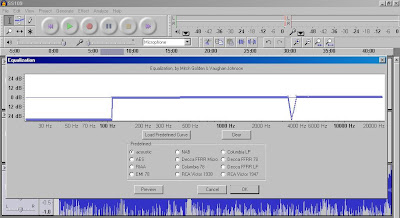
In SolderSmoke 109, I did a little experiment. Normally I do some audio processing using Audacity's Equalization option. In all of the recent episodes, I have been using an equalization curve similar to the one shown above. I drop off the low frequencies (to get rid of the Popping P sounds) and I put a notch at around 3500 Hz in an effort to get rid of the problematic SSS sounds. I had my doubts about the effectiveness of all this. Partly in an effort to save time, SolderSmoke 109 I dispensed with the processing. I immediately got a couple of e-mailed signal reports saying that the nasty SSSS sound was back.
I really can't hear it on my computer. This may be related to different sound cards. And some high frequency hearing loss that I picked up on the rifle range may be involved.
If you can, please compare the sound quality in SS108 with that of SS109, and let me know what you think.
Dean, WA6P, and Bill W7AAZ, going to send me a passive audio filter that we hope will help.
On a similar note (!), I am looking for a circuit for a simple audio signal processor for use with my DSB rigs. I need something simple that will provide both clipping (probably via the standard two diode arrangement) AND audio frequency selection. The ability to put upper and lower limits on the audio frequencies is important in DSB rigs, because they lack the crystal filters that do most of this work in SSB transmitters.

Monday, June 8, 2009

SolderSmoke -- The Book. Table of Contents

As promised in SolderSmoke 109, here is the Table of Contents for the new SolderSmoke book.

CONTENTS
Preface

Chapter 1 Electrically Inclined – Tales of an Electromagnetic Youth
Electrons and Electricity
Radio Waves
Some Basic Equations
Einstein in the Transformer
Semiconductors

Chapter 2 Off-the-Air—Amateur Radio Goes Into Hibernation
Junctions and Diodes

Chapter 3 Tropical Rebirth—Ham Radio in the Dominican Republic
The Lowly Capacitor
Resonance and Oscillation
Series and Parallel Tuned Circuits

Chapter 4 Boatanchors in Virginia—Back in the U.S.A.
Transistor Amplifiers
Mixers
Modulation: AM, DSB, SSB

Chapter 5 Mid-Atlantic Outpost—Amateur Radio from the Azores
Balanced Modulators

Chapter 6 Urban Radio—Solder Smoke in Central London
Amplifier Loads

Chapter 7 Rome—Secret Radio in the Eternal City
Feedback in Amplifiers

Chapter 8 Conclusions—A Brotherhood Without Borders

Acknowledgements

Index

To order: http://www.lulu.com/content/paperback-book/soldersmoke/6743576

Sunday, June 7, 2009

SolderSmoke Podcast #109

http://www.soldersmoke.com
June 7, 2009

Violin gig in Rotterdam
June 2 Parade in Rome
Why do we use Rl=Vcc^2/2Po for Class C amps?
NA5N article, EMRFD, SSDRA, LTSpice
Radio Signals from Jupiter and Io (on 17 meters)
VK2ZAY's X-Rays
Jeff Damm, WA7MLH: Homebrew Hero
Tim Walford's Constructor's Club:
Floor Polish as PCB Laquer
Numbers Stations (very timely!)
SolderSmoke -- The Book: Very rapid delivery, even to UK
MAILBAG

Friday, June 5, 2009

The Look of a True Radio Homebrewer

Jeff Damm, WA7MLH, is one of our gurus, a high priest of The Knack. I visit his excellent site from time to time, just on the off chance that he will have posted something new. This morning I was rewarded with this picture from 1988 -- I think it somehow captures the spirit of the true radio homebrewer. Check out all the homebrew gear. Note the copy of SSDRA on the operating table. Jeff assisted with the construction of many of the projects in that book. He helped free us from the tyranny of excessive neatness and right angles, and let us know that ugly circuit construction works just as well.
Here's Jeff's FB site: http://www.neoanderthal.com/wa7mlh1.html

Thursday, June 4, 2009

Walford Electronics

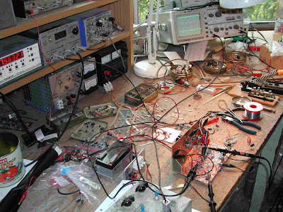
Tim Walford, G3PCJ, offers a really nice line of ham radio kits. I like the names of the products, and of course I really like the DSB kits. The photo above is the workbench on which these rigs are created. Tim also runs a Construction Club and puts out an excellent quarterly newsletter called "Hot Iron." I just received the latest issue, which is a particularly good one -- more about this in SolderSmoke 109.

Here is a list of Tim's kits:

AMU Matching bridge and T match for 10 - 160m
Audio Amplifier General purpose amplifier for driving a loud speaker
Audio Extras Adds AGC and good CW facilities to a phone TCVR
Brendon Small DSB 1.5W phone transceiver for 80m
Brent Small 1.5W CW transceiver for 80m
Chirnside Regen RX, crystal controlled AM TX, for any band to 6m
5D Counter Five digit frequency readout
Dual Low pass filter Pair of relay selected Low Pass Filters
Fivehead Single band 1.5W SSB phone TCVR for 20 - 160m
Kilmot Double sideband 80m 1.5 W phone TX
Kilton 1.5 Watt CW TX - 20 to 80m
Kingsdon 5 Watt phone SSB and CW transmitter to go with Midney
Knapp Single Band regen TRF - 3.5 to 15 MHz
Knole Single Band DC RX, 20 to 80m
Linear 10 Watt RF amplifier for all nominal 1.5W rigs
Midney Simple single band superhet RX for any band 20m to 160m
Mini mix Mixer kit for VFO schemes or as receive converter
Notch filter Variable frequency notch or peak audio filter
Speech processor Boosts average signal level under difficult conditions
Trull Medium Wave regen TRF for newcomers, can also do HF
Two Tone oscillator Provides audio tones for setting up SSB rig
Washford Crystal controlled 1W CW TX for 20, 40 and 80m
Willet Simple direct conversion RX for 20, 40 and 80m

Here is the website of Walford Electronics: http://walfordelectronics.co.uk/

Wednesday, June 3, 2009

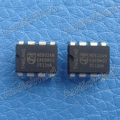
NA5N on the NE602


I continue to mine the Gadgeteer News archives.
Here is a good one from NA5N.

Orignally posted on Gadgeteer news, 2 December 2006
NE602=NE612=SA602
(Originally posted by NA5N on QRP-L)
Gang,
The ever famous NE602's are manufactured in the Philips
Semiconductor plant in Albuquerque, about 85 miles north of me. I visited
there last summer and had a nice discussion with an applications engineer
about the history of the NE602's. Goes something like this:

This long story will prove that NE602 = SA602 = NE612 = SA612
(for those of you who don't want the gory details -hi)
The original NE602 was designed/manufactured by SIGNETICS for
the 45MHz FM wireless telephone market. A little later, the wafer was
redesigned a bit to allow the internal oscillator to operate to 200MHz and the
RF to 500MHz. This was redesignated the NE612, and was intended to
replace the NE602. However, customers kept ordering the NE602, getting
angry at Signetics because their distributors were out of stock, etc. So when
they made the chips, they made a jillion NE612's, and labeled some of them
NE612 and the rest NE602 to satisfy the users of both parts. This is why
contemporary data books show the exact same specifications for both NE602
and NE612. They came from the same wafer.

Then Signetics was bought out by Philips, who evidently
continued this practice for a short time, then decided it was rather
redundant. So they announced that the production of NE602's has been discontinued
and listed it as an obsolete part ... giving QRPers around the world
various fits of apoplexy to suicidal tendencies that doomsday had struck.
What wasn't well understood is Philips continued to support production of
the NE612, as they do today.

Then to make matters worse, disaster struck the Philips plant
in Albuquerque in the spring of 2000. A wild grass fire in
northwest New Mexico threatened three main electrical lines that run from
the "Four Corners" electrical generating plant to Albuquerque. Smoke
from the fire caused one of the high-voltage lines to arc, tripping the
circuit off line. Virtually the entire electrical load for Albuquerque
and southern New Mexico was now transfered to the two remaining feeders,
which could not handle the full load, causing brownouts, voltage spikes,
etc. until they too failed. Where I live in Socorro, New Mexico, I
remember the brownouts hit about 4:15pm, outages on and off until the
entire grid went down about 5pm, and stayed off until about 11pm. One of the
longest power failures in US history. We just figured it was Y2K about 3
months late. (PS - I worked 40M CW QRP that night by candlelight, and it
was the quietest conditions I ever heard on 40M!!! And every QSO I
heard seemed to be a QRPer). The extreme voltage fluctations as the
feeders were failing caused a transformer at the Philips plant in
Albuquerque to catch on fire. I remember seeing it on the TV news, in which they
said it caused mostly smoke damage from the burning transformer and
burned a couple of storage rooms. That was all-no biggie. Well, it
turned out one of the storage rooms that was burned was where they stored
the film masters for making the semiconductor dies, and the NE612 film
master was now molten emulsion. These film masters were the originals
from the old Signetics company. So Philips had to completely redo the
artwork for the majority of their IC's. Additionally, it turned out the
smoke damage was excessive and the IC fabrication facilities were
left unusable. Philips was basically unable to manufacture IC's at
the Albuquerque plant for months. It was about 8 months before
they got all their wafer machines back on line, which left a huge hole in
the semiconductor industry. I know it just about killed several
cell phone manufacturers because delivery contracts for parts were
suddenly postponed for six to eight months.

The world wide supply of NE602/NE612's virtually dried up
during 2000 as a result of this fire and the nearly year backlog of
manufacturing quotas. The first run of NE612's in 2 years finally occured in
September 2000.This huge shortage of NE612's, combined with the fact that
NE602's have been discontinued/obsolete, is what convinved QRPers that
these nifty little chips were no more. I was told 20,000 units were
manufactured in 2000, or what Philips believes is a 2 year supply. This is
also why the release of the K1 (with 5 NE612's!) was delayed from the
promised "after Dayton" to late in the year, as were other kits. It just
wasn't clear when Philips was going to schedule the NE612's for production.

So yes, the NE602 is dead, but the perfectly compatible NE612
is still available, and Philips has no plans at the present to
discontinue that part number.

For final clarification:
NE602 = plastic DIP, rated 0C to +70C ... OBSOLETE
SA602 = plastic DIP, rated -40C to +85C ... OBSOLETE
NE612 = plastic DIP, rated 0C to +70C ... AVAILABLE
SA612 = plastic DIP, rated -40C to +85C ... AVAILABLE

or, to answer the final question ...
NE602 = SA602 = NE612 = SA612

72, Paul NA5N

Tuesday, June 2, 2009

Alan Yates Making X-Rays from Rectifier Tubes

Anytime you find yourself writing a sentence like this...
"At only 20-30 kV and a few hundred uA in cold-cathode mode the x-ray radiation pours out, making the end-window Geiger counter scream from more than a meter away."
... perhaps some alarm bells should be going off.

Our friend Alan, VK2ZAY, has been busy in the lab, generating X-Rays from old 2X2 rectifier tubes. This reminds me of one of the articles in the wonderful C.L. Strong book, "The Amateur Scientist." Check it out: http://www.vk2zay.net/article/222

Hey Alan, can you make us up some of those X-Ray glasses that they always advertised in the backs of magazines? As a teenager, I somehow always wanted one of those...

Class C Amps and the Load and Power Out Formulas

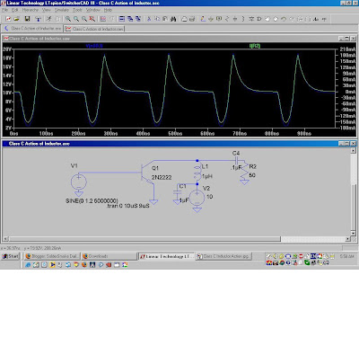
While up in Rotterdam I started thinking about Class C Amps and the standard formula used to calculate power out and load resistance: Rl=(Vcc-Ve)^2/2Po. I understand why this formula works for Class A amps: The Vcc-Ve term describes the maximum voltage you can get at the output. The rest of the formula is just a version of P=IE and P=E^2/R. The 2 in the denominator converts peak to average. The books tell us that this same formula applies to Class C amps. How could that be? I wondered. Doesn't the output of a Class C amp look (pre-filter) like a series of pulses at the operating freq? Wouldn't that require a somewhat different formula?
The answer came from SSDRA and LTSpice. SSDRA page 25 explains "If we assume that the collector voltage varies from zero to twice the Vcc level while delivering the desired output power, the load needed at the collector is given by the familiar relation Rl=Vcc^2/2Po." (Emphasis added.) The voltage at the collector is being pulled down nearly to zero as the voltage at the base goes positive and the transistor conducts. You can see this in the waveform in the LTSpice screenshot above. Then, when the input voltage dips below about .6 volts, the transistor goes into cutoff and stops conducting. At this point the energy stored in the inductor in collector circuit is dumped onto the collector, raising the voltage there to about twice Vcc. That the ugly spike you see at the top. Wow, you can really see from this the need for output filtering.
As I was exploring this issue, I cam across an old LTSpice VideoCast from December 2006. See below.
BTW: These are the kinds of questions explored in the book "SolderSmoke -- A Global Adventure in Radio Electronics." I'm hearing that delivery is very fast, especially in the UK.

Saturation and Class C Amplfier Efficiency

Originally posted on Gadgeteer News: 10 December 2006

FIRST LTSPICE VIDEOCAST

I made a 5 minute video using a video screen-capture program and the circuit simulator LTSpice. In addition to showing how LTSpice can
be used, the video looks at how saturation affects the efficiency of Class C amplifiers. I put the file on YouTube, but the video quality is poor when viewed through that service (it is difficult to see the graph lines in the YouTube version). So I have also uploaded the 26 meg file (.wmv)
to the http://www.gadgeteer.us web site.

Click here for the direct download of the .wmv file

Click here for the YouTube (lower quality) version

Monday, June 1, 2009

Thoughts on Minimalist Radio

I had a lot of good articles on the old web-page version of this blog. I want to get them into the index, and the only way I can think of to do this is by posting them again. I don't think this is a problem: many readers will have never seen them, and even for those who have, many of these are so good they deserve a second look. This 2006 piece by KK7B is a good example (The picture is from Roger, KA7EXM's FDIM 2007 photo collection and shows KK7B winning a toroid winding contest):

A FEW THOUGHTS ON MINIMALIST RADIO FROM KK7B
(Originally posted on the EMRFD Yahoo group)

If you really want to do minimalist radio, you may want to step way
back and take a look at some very early history. The Pixie circuit
has many more components than an early CW station from the era
immediately after spark.

Rather than starting with the Pixie and trying to figure out what to
eliminate, maybe a better approach is to start from zero and decide
what you need. Combining transmit and receive functions is the last
thing to think about.

Starting with the receiver.... The first thing you need is wire up
in the air. The more, the better. If you have the real estate for a
full sized dipole on 80 meters, you can collect enough signal energy
to hear on a crystal set when conditions are good. I've copied CW
signals on 40 meters with just a dipole, transmatch, a 1N34 diode, a
good pair of headphones, and a one transistor Pierce oscillator
running on the bench. The leakage from the crystal oscillator picked
up by the antenna beats against the incoming signals. I didn't power
the oscillator with lemon juice, but I could have (see Bob Culter and
Wes Hayward, "Lemonized QSO" in March 1992 QST.)

Then for the transmitter, just heat-sink the Pierce oscillator and
key the connection to the load. The shift in load impedance will
offset the crystal oscillator frequency.

A dual pi-net transmatch configuration would take care of the
harmonics and allow maximum energy transfer between the antenna and
diode--but I'd analyze it to make sure the harmonic suppression is
more than legal.

So far I count 5 components for the dual Pi-Net transmatch, a 1N34
diode, 6 components for the one-transistor Pierce oscillator. A
dozen parts, plus headphones, a key, and battery--or some electrodes
to push into a lemon.

That would make contacts, but Wes and I have discussed a basic rule
for radios, which is that a station should be able to work an
identical station over a distance of a few miles. It could probably
be done with the above station, but a single transistor audio
amplifier running at maximum gain between the 1N34 and headphones
would make it possible to extract many more signals from the 80 meter
dipole. That's another 5 or 6 parts. So now I'm up to about 20.

For a more serious station, I'd probably add two more transistors and
a diode, so I could have a separate PA, a balanced mixer, and two
audio stages. The receiver would end up looking a bit like EMRFD
figure 8.7 with a PA tacked on. That would have about 35 parts, but
it would be able to work DX off the ionosphere...about the same
complexity and performance as many other variations on the theme. A
previous version of the Pixie from the 1970s was called "The
Optimist."

Unlike Muntz--instead of starting with someone else's circuit and
trying to eliminate parts until I had something that just barely
works, I'd start from scratch, study EMRFD (and other references too--
but in EMRFD all the circuits have been designed and tested) for
circuit ideas, and then start experimenting on the bench, one stage
and one component at a time. Since one of the joys of minimalist
radios is that they can be understood all the way down to the device
physics, I avoid ICs. (I particularly avoid cell-phone ICs, which I
designed for a number of years. It's like working in a sausage
factory--you are much happier if you don't know what's inside.)

Minimalist radio is one of the more interesting design games that we
play using the methods of EMRFD. It's cheap, it's interesting...and
as we dig in, we discover that the details can be every bit as
challenging for a radio project with 30 parts as one with 30,000.

Have fun.

Best Regards,

Rick kk7b

Saturday, May 30, 2009

In Rotterdam

I'm up here with Billy on a violin gig. Beautiful place! Will descrbe
on next podcast. 73
Designer: Douglas Bowman | Dimodifikasi oleh Abdul Munir Original Posting Rounders 3 Column