Podcasting since 2005! Listen to Latest SolderSmoke

Sunday, September 4, 2016

First Signals from the "Armand HROish" Receiver


I've been kind of busy lately with other things, but I have managed to squeeze in a few minutes most days to work on my latest receiver project.  I call it the Armand HROish receiver.  Armand WA1UQO sent me the big National HRO-style dial and gear box, and he was there at the Manassas hamfest when I bought the dual variable cap that now serves in the front end pre-selector.

I went with a 455 kHz IF.   The idea is to have a receiver that tunes from around 6.5 MHz to around 8 MHz so I can do some shortwave listening AND listen to 40 meters.

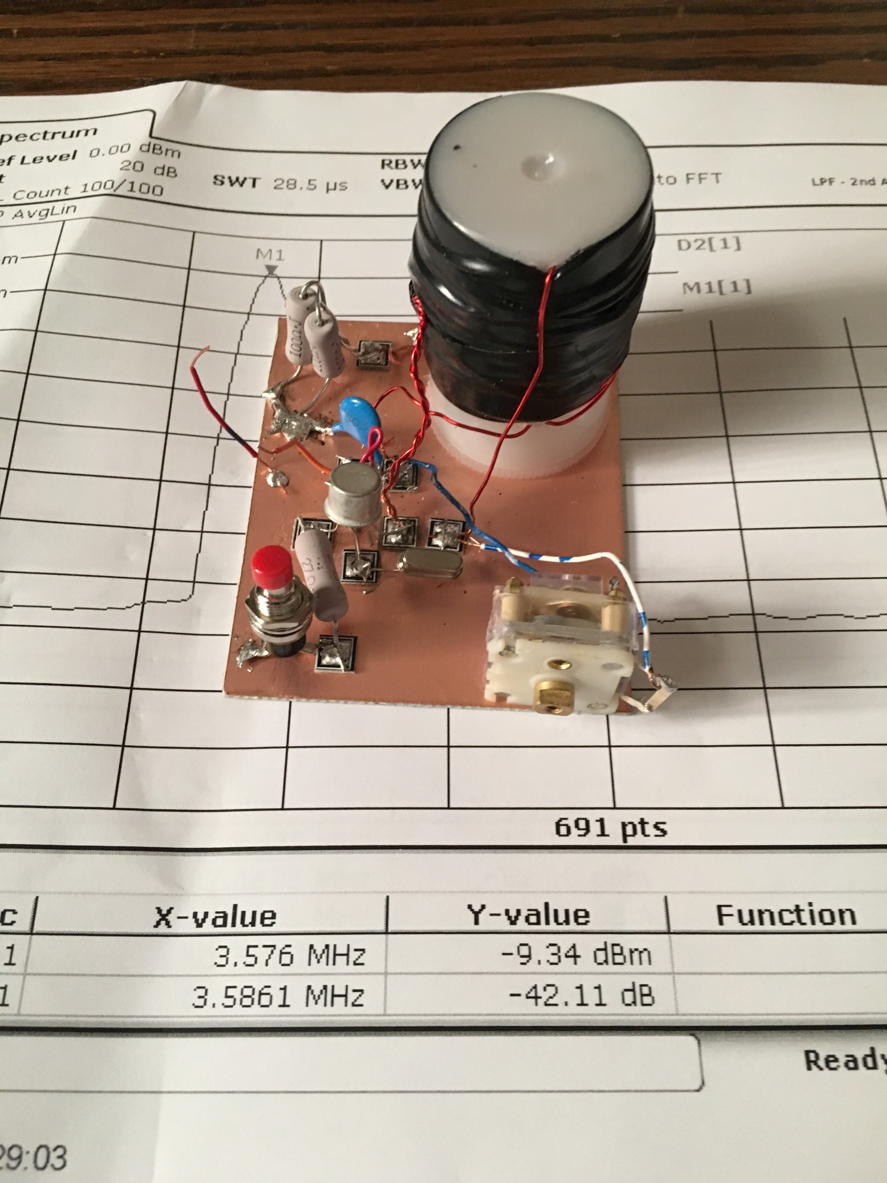
So far the filter consists of three IF cans (one small transistor can and two larger tube-type cans).  The small transistor can was given to me by Michael Rainey AA1TJ - thanks Mike. Doug DeMaw suggested this use of IF transformers in his "Design Notebook."

At the front end I have a tunable dual tuned circuit filter followed by a 40673 amp. 

The mixer is an SBL-1.

1st and 2nd IF amps are a 23 db 50 ohm termination insensitive amplifiers.

I have a second SBL-1 that will be the product detector, but I haven't built the BFO yet.  So today I hooked up two 1N34A diodes in voltage double config and -- with a bit of AF amplification, got the receiver inhaling with a diode detector.   I could pick up Radio Canada.  Then I heard SSB sigs on 40.  With no BFO, I decided to put my sig gen on 455 kHz and just wrap the lead around the IF cans.  It worked -- I could listen to SSB and CW sigs.  Very satisfying. 

Still to do:
-- BFO and product detector.
-- Work on AF amp.
-- Get my CM-455 crystal mechanical amp in there with some relays around it so I can switch from narrow to broad via the front panel.

Lots of soul in this receiver:  All parts either 1) came out of the junkbox, 2) were gifts from friends, or 3) were recent hamfest purchases.  The HRO dial from Armand and the IF can from AA1TJ.  The 455 kHz filter idea came from Doug DeMaw, the VFO circuit from SSDRA.  The VFO base is from Whole Foods and the whole thing is built on a kitchen cutting board. It includes a 40673 and germanium diodes. The VFO amps are in Altoid tins.  It will, when finished, go into a big metal box given  to me by Tim KI6BGE and shipped east by Pete Juliano.  And when I was working on the 1st mixer, I accidentally pricked my finger and a drop of N2CQR blood went onto the breadboard.  Of course, I left it there.   SOUL!

The Radio Gods are apparently pleased:  In the first hour or so of listening, I was rewarded for my efforts when I managed to hear Tim WA1HLR on 40 AM describe his troubleshooting of an old piece of gear.  TRGHS.  


Wednesday, August 31, 2016

A Signal for SETI? HD 164595


That's the Russian radio-telescope that picked up what was thought to be a possible signal from an extraterrestrial civilization.   This article from the SETI Institute has some interesting tech info on antennas and power levels.  Definitely not QRP!


Monday, August 29, 2016

Update on the PA3GSV M4MMRX -- And a Mystery


Note the establishment of a new acronym (M4MMRX) for Lew McCoy's Mate for the Mighty Midget receiver.  We  have needed this acronym for a long time, and SolderSmoke HQ is proud to have come up with it.  We do our part my friends.

Jan has made more progress on his amazing Dutch M4MMRX and has produced a short video showing the receiver in action with SSB and CW signals. 

Here is a bit of intriguing homebrew mystery:  Jan has gone to a LOT of trouble to create that semi-circular opening in the center of the front panel.  He even cut a corresponding semi-circular hole in the sewer pipe cap that serves as the large wheel in his amazing homebrew reduction drive.  But he won't tell us what he plans to do with that space.  So I ask you, dear SolderSmoke readers:  What is that space for?  Why the see-through panel and sewer-pipe cap?  What is Jan's plan? 

From Jan:

Hi Bill,
 The rattle is gone, so I made a little video of the MMMRX in ssb and cw mode.

In the text, a ch327 and a ch45 crystal is mentioned, but I can’t get this to work.
The ch45 has a 453.6 kHz fundamental, for ch327 can’t find one.
The ch327 is a FT-243 one, tested several, but no fundamental somewhere around 455 kHz.
For ssb there is a ch45 and a ch46 crystal in, which should provide a bandwidth of about 2kHz.
(Still not totally in the clear how this should work with the very narrow resonance response of the crystals.
One should expect two peaks and nothing in the middle?)
For cw I found two ch45 crystals about 130 Hz difference in frequency, which seems to work well.

Still need to correct the 40m oscillator coil, then move on to finishing the receiver.
This is my first home brew tube superhet.
The project isn’t finished yet, but it sure is fun to build, and learned a lot during the process.

73  Jan

Sunday, August 28, 2016

40673 LTSpice Model?

Does anyone have an LTSpice Model for the venerable 40673?  Or for a similar MOSFET?  I'm hoping to find something that I can easily plug into LTSpice. 

Friday, August 26, 2016

The NAA VLF Station (NOT QRP!) and Brad's Receiver

NAA Towers -- Arlington Va. 1913

Brad WA8WDQ wrote to us about a VLF (24 kHz) his receiver project (see below).  This led to some Googling about the VLF station NAA.  Wow, there is some important radio history associated with that call sign.   The station's original location was just a few miles from I where I live now.  From Wikipedia  (https://en.wikipedia.org/wiki/VLF_Transmitter_Cutler):

The station began operations in 1913 as a radio telegraphy station call sign NAA in Arlington, Virginia, at a facility next to Fort Myer. Although its broadcasts occasionally included band concerts and speeches, it was most famous for its nightly time signals. The three towers known then as "The Three Sisters" stood 600 feet, 450 feet and 200 feet (183, 137, and 61 m) above the ground. The site was referred to as "Radio", Virginia. The towers were the second largest man-made structure in the world behind only the Eiffel Tower. The word "Radio" was first used instead of "Wireless," in the name of this Naval Communications facility. The First Trans-Atlantic voice communication was made between this station and the Eiffel Tower in 1915. The Nation set its clocks by the signal and listened for its broadcast weather reports. The Towers were dismantled in 1941 as a menace to aircraft approaching the new Washington National Airport. The towers stand today at United States Naval Academy in Maryland, on the edge of the Chesapeake Bay. 

Be sure to read about the de-icing system for the antenna.  It uses more power than the actual transmitter!

From Brad:

Bill, Pete,
Here's the current status of the 24 KHz NAA SID receiver.  All the major sub-assemblies are mounted in the chassis and power is hooked up.  For convenience, I've been using the PowerWerx USBbuddy switching DC-DC converter to supply +5V power to the Raspberry Pi from the +12V input.  I've found them extremely RF quiet, clean and stable; capable of supplying 3A though this project will only need about 1.5A @ +5V.  At this point, I'm just waiting for Adafruit to send the A/D chip I'll wire up to the Pi on that empty protoboard just under the meter.  Speaking of the meter, it's not really needed as the Pi records and broadcasts over Wi-Fi the received signal level.  However, I like my projects to have some sort of physical human interface so I added the signal level meter and an LED for SID event alarms :).

As previously mentioned, my bench test of the receiver using my signal generator was successful.  Once everything is wired, I'll do an actual on-air signal test receiving NAA.

Brad  WA8WDQ


Monday, August 22, 2016

Radio New Zealand Booming in on 7245 AM

The day is off to a good start here at SolderSmoke HQ, with Radio New Zealand booming in on my homebrew Mate for the Mighty Midget receiver.  I was listening from around 0900 to 1030 UTC on 7245 kHz. Once again we see that The Radio Gods favor homebrew receivers. Gray line propagation also played a role.  

Above we see a technician at work at RNZ in 1945.  More historic photos here:
http://www.pcc.govt.nz/About-Porirua/Porirua-s-heritage/Porirua-s-suburbs/Titahi-Bay/Historic-site--Radio-New-Zealand-Transmission-Station

Sunday, August 21, 2016

First Signals from the PA3GSV Mighty Midget Mate


Obviously the Radio Gods (Spirits in the Sky) approve of Jan's work.  How could they not?  I can now see why he took the trouble to cut that hole in the sewer pipe cap that forms the large wheel on his homebrew reduction drive.  But what are we going to see through that center hole Jan?  What will the frequency readout be like?  
----------------------
Hi  Bill,

Just finished the last stage of the Mighty Midget MK2.
There are first signals!
The first one I heard was a broadcast station, believe it or not, the song that was on was “Spirit in the Sky” ..
All stages were built, tested and as far as possible, adjusted separately.
It was built from back to front, so the RF amplifier was last.
I added an ECL82 for more audio, the first thought of only using an EL84 didn’t bring enough.
The triode of the ECL82 as a pre-amp, the pentode as final.
Furthermore ECF82’s were used instead of the 6U8, they’re more widely available over here.
The Miller coils are hard to come by, so the 300 uH coils are homebrew.
Also used a grid detector instead of the two germanium diodes.
The triode of V1 originally intended for audio was used for this.
Made the BFO adjustable as well, still remember the screwdriver sticking out of the coil on your side... 
 
Happily there was not much troubleshooting needed.
The 80m coil was only 5 kHz off, the 40m coil 300 kHz (to low in frequency), still have to fix that.
Initially the receiver worked reasonably well without adjusting, but C1 quit at some point.
After some investigation, the problem was a dirty wiper contact on the rotor.
An ultrasonic bath fixed the problem, so no looking out for a replacement there. (hope it stays that way)
 
After adjusting, sensitivity is around -114dBm (0,4 uV) / 10 dB S/N!  (with the FT241 crystals in place, and careful tuning of the controls)
Really not bad for this small receiver, Lew McCoy was right, it really is a Mighty Midget.
I wanted to make some video’s, but over here there’s a terrible S9 rattle from 160 to 15 meters.
Every now and then it appears out of nowhere, and disappears the same way.
As soon as it is gone, I’ll make some video’s.
I made one video though, just after completing the receiver.
 
 
Reception on CW and SSB sounds really well, but unfortunately didn’t record that.
The receiver is not finished yet.
Next to the 40m coil,  S-meter has to be tried, and there’s still some work on the cabinet and front panel.
 
More to follow.
   
73  Jan
PA3GSV

Wednesday, August 17, 2016

N7UN Talks About Summits on the Air (FDIM Interview by Bob Crane)

Bob Crane, our intrepid correspondent at the Dayton Hamvention talked to Guy N7UN (pictured above) about taking ham radio up to the mountaintops.  It was nice to hear Guy mention Wayne Burdick and Wes Hayward and WG0AT.    Thanks Bob!  Thanks Guy!

Listen here:

http://soldersmoke.com/N7UN.mp3

More on N7UN here:

http://www.n7un.com/


Tuesday, August 16, 2016

Reggae Knack?

Could it be that Bob Marley's son Ky-Mani has The Knack? Probably not (no mention of it in Wikipedia) but he certainly has some nice old receivers on his 2007 album cover.

Monday, August 15, 2016

The Joy of Analog Oscillation -- A Character-Building Experience

Gentlemen,
I'm a younger ham, just 26, and I've just experienced what I think you call Joy Of Oscillation as I completed my first L-C VFO. What fun!

I'm working on Peter Parker VK3YE's
Beach 40 Double-Sideband transceiver, and while my natural proclivity is toward the SI5351 and it's brethren, I figured it would be character-building to actually put together an analog VFO for once.

After much tweaking of the feedback capacitor in the oscillator, and massaging the tank inductors, and conking out an additional buffer stage to drive the diode-ring mixer at the appropriate level, and gluing Manhattan pads on top of Island pads.... I say, without reservation, that this was
great radio fun! And isn't that what it's all about?
(Now it only it didn't drift so much... so I guess it's not quite complete yet)
Just wanted to share, love the podcast and the blog, I learn something new each episode.

All the Best,

Jeff, KK9JEF

---------------------------

Great stuff Jeff.  Character building indeed!    As for the drift, try this:

-- Replace the toroid in the oscillator circuit with a coil wound on a non-metallic core.  I use a cardboard tube from a coat hanger.

-- Make sure the capacitors in the oscillator and even in the buffer are NP0 caps (they don't change in value as they heat).

-- Try to run the oscillator stage at reduced voltage.  Six volts is better than nine.

--  After you solder, always let the device cool down for several hours (or even overnight) before you evaluate it.  Heat from the soldering iron will be dissipating and changing the freq for a LONG time.

Above all, IGNORE the inevitable recommendation from Pete Juliano that you forget about all this nonsense and just go with an Si5351.

Please keep us posted on your progress. 
73  Bill   N2CQR


Sunday, August 14, 2016

An Irish Knack Story


I think Tryg should get that Ladybird receiver working again. 
-------------

Hi Bill,

Thanks for the great podcasts and also to Pete for his unique contributions. I have been interested in radio since I was a kid but only really got back into the hobby in 2009. Back when I started playing with electronics in the 1970's I hankered after a soldering iron of my own. I bought the one in the picture in 1977. A "modest" 60 watt job, it was the cheapest one in the shop but I used it to harvest parts from all manner of abandoned old iron. I was really surprised to find it clearing up recently. The snips in the picture was a tool that my late Uncle had surplus and passed on to me, it too played a role in my scavenging for parts. In Ireland in the 1970's it was hard to get parts. I remember my Grandmother taking me from Galway to Dublin - 3 hours each way!!!) to buy parts for my first project, Rev. G.C. Dobbs venerable transistor radio from the "Making a Transistor Radio" book by Ladybird. I still have the book and the dusty remnants of the radio, long since plundered for parts. When I returned to the world of radio it wasn't long before I discovered QRP and the GQRP club. It was a real surprise to find the good Reverend was at the helm there. I just thought that the picture and story might raise a smile amongst followers of the blog. Thanks to yourself and Pete for the podcast. Keep up the great work! QRP Forever!

73,

Tryg de EI7CLB

---------------------


Saturday, August 13, 2016

KB8M's Mighty Mite -- Beware the Treacherous P2N2222!

Doug KB8M did a beautiful job with his Michigan Mighty Mite.  But, as often happens, it still didn't work. He turned to us for advice.  I gave him a long list of things to check, but Pete brought the power of superior tribal knowledge to the problem and spotted the defect immediately: The transistor was in backwards.  It is a P2N2222.  That means the pin out it C-B-E  not the usual E-B-C.  I had fallen into this trap with one of my BITX rigs and had to pull out and reverse many of those transistors.  Fortunately for Doug he had used a socket for the transistor.  TRGHS!!!!!!!!!!!!!  JOO!!!!!!!!!!!


Wednesday, August 10, 2016

Some Really BIG Coils

I met W1VLF on 40 meters last week.  "VLF" was a hint.  And indeed, Paul has been experimenting in the 10 kHz range.  His antenna loading coil is seen above.
More info here: http://rescueelectronics.com/9-Kilohertz.html
Very cool that Mike was working with Jay Rusgrove, W1VD, on this project.  Jay designed the 6 watt VXO rig that was my first homebrew transmitter.

And additional VLF info here:
http://n3cxv.com/WH2XND_station_1.pdf

Saturday, August 6, 2016

SolderSmoke Podcast #189: Juliano Blue, FET Amp, Si5351 QSK, Bill LC VFO, QSOs


SolderSmoke Podcast #189 is available:

http://soldersmoke.com/soldersmoke189.mp3

Billy in Europe.  Bill in Virtual Reality. 

Great News:  Little Gonzalo is "all clear."  Thanks for the help.

BENCH REPORTS:
Pete paints the rigs blue. 
Pete's FET amplifier project with FET switching and key pad
Using an Si5351 for CW offset and QSK.

Bill working on VFO for a rig built around HRO dial and gear box.
HRO gears seem a bit loose.  What should I do?
The search for an Imperial Whitworth.
For variable caps, brass is better, but two bearings beats brass.

QSO REPORTS
Pete having fun with homebrew rigs.
Bill works K3MRK, WA3O, W4OP, W1VLF and N6ORS

MAILBAG:
Dallas CBLA
Conventional Current Flow Controversy
"I regret ever listening to your podcast!"
LCR recommendations


Gonzalo just turned TWO and is doing very well

Thursday, August 4, 2016

Dallas Mighty Mites from a MakerSpace


Monday, August 1, 2016

Walking the Plank with N8NM's 60 Meter Rig

Steve N8NM writes:

The free-range rig is coming along!  I'm receiving with decent sensitivity (my generator's only calibrated to -100 dB/m, and I hear a CW note there just fine) and I'm getting about -2 dB/m out of the mixer.  Yippee!
I ended up using an IF of 20 MHz, mainly because I had a bunch of crystals left over from my Minima.  The architecture (left to right) is: Diode ring mixer using 1N4148s, 20dB W7ZOI bilateral TIA, 6 pole crystal filter (BW ~= 2.3 KHz), Another 20dB bilateral TIA, 1N4148 product detector (cribbed from the Minima), 2N3904 audio driver, LM380 PA.  Microphone amp is two FET stages (J310).  Oscillators are courtesy of an Si5351, controlled by an Arduino Uno.  T/R switching is done using a couple of counterfeit 2SC1969 RF transistors that, ironically, don't amplify at RF, but work fine as power supply "pass" transistors.
Yet to do is the PA, which I've noodled in LTSPICE (shooting for 20W PEP using a bunch of BD139s, just because...) and cleaning up my Arduino sketch.  Right now, I just modified the start-up values of the sketch from my all-band rig for testing.  Since that code is pretty full featured (dual VFOs, RIT, filter switching, LCD Display, etc.) using multi-function pushbuttons to select all sorts of crap, I'm betting that 80% won't be used in this rig.  Adding simplicity is always good.
So, nearing the end, I'm already thinking about my next rig (that and building a 60m antenna...)  I think this one will be similar to my "all band" rig, but limited to the WARC bands (I have a WARC tribander that's screaming for a rig of it's own.)  That's kind of boring, so, to challenge myself, I'm going to try using a touch screen in lieu of the usual pushbuttons.  What would really be cool, though, is an interactive slide-rule dial - don't think anyone's done that before!  One of the things that has always drawn me to the SX-101 is that large slide-rule dial.  To me, that allows each station to occupy a physical place on the dial, so after scanning the band, you know were everyone is.  It's really a joy to operate those rigs!
73!  Hope to work you HB2HB on 60M soon!
-Steve

Sunday, July 31, 2016

W9ZN's CW Warm-up: "Ben's Best Bent Feet"


I happened to come across this fellow's signal on 40 a week or so ago.  His warm up routine really had me scratching my head.   I've been on the air for a long time, much of it on CW, and I never heard anything like this.   Listen to the video (!) and you will see what I mean. Harmless fun I guess, and there does seem to be a connection to radio history. 

Saturday, July 30, 2016

Pilgrim's Progress: A Peregrino Rig Concealed in a Book


On the G-QRP list guys have been talking about the Peregrino.  This is a nice little homebrew rig out of Spain.  Peregrino = Pilgrim and usually refers to people who are hiking along the Trail of Santiago that runs through the North of Spain to Santiago de Compostela.

I'm normally averse to chips, but this little rig uses two very understandable NE602s and an equally understandable LM386.  It has a homebrew crystal filter.  I like it.

GM4WZG came up with a really wonderful enclosure for his rig.  This reminded me of the time I put a QRSS transmitter inside a copy of "The DaVinci Code."

The Spanish guys have a nice site that describes the rig.  Google Translate should help, but even without it you can get most of the info you need from the schematic, chart, and foto gallery.  Check it out: http://ea3ghs.qrp.cat/peregrino.html

Enhorabuena!

Thursday, July 28, 2016

Juliano Blues


Pete swears the rigs work better with this color. 

We are adding Sherwin Williams "Juliano Blue" paint to our investment mutual fund: Drake 2Bs, copies of SSDRA, QF-1 Q Multipliers and now, Juliano Blue! We'll all be RICH!  

Tuesday, July 26, 2016

Which way does current REALLY flow?

I've talked on the podcast about launching a worldwide campaign to require the reversal of ALL those little arrows on the symbols for transistors and diodes.   You see, they are saying that electricity flows from the positive to the negative.  Engineers apparently got that idea from Ben Franklin, and they are sticking with it.  It is time for a change!   Reverse the arrows!  Down with CCF!  Viva Electron Flow!  Let's tell the truth!

This morning Bob Crane W8SX sent me this very interesting article on this topic from Nuts and Volts:

http://www.nutsvolts.com/magazine/article/which-way-does-current-really-flow?utm_source=Newsletter+%2332&utm_campaign=Newsletter+%2332&utm_medium=email

The article describes very well the origins of this controversy. (There were one or two scary moments in which I thought the author was getting ready to tell us that positive ions can move through wires and transistors (NO!) but he pulled back from the brink and clarified that he was talking about ion flow in electro-chemical batteries.  Whew, that was scary!)

But here's a question for the philosophers and historians of electronics:  When physicists decided to label the electron as "negative" this was an arbitrary choice, right?   They could have just as easily decided to call it "positive" with the protons being called "negative" right?  In this case all the arrows in our diagrams would not be in need of reversal, right? 

Monday, July 25, 2016

Shotwell had the Knack (Car Knack), and so does Jay Leno


I've joked about homebrew cars -- we have a bumper sticker on Café Press that says "My Other Car Was Homebrewed From Junkbox Parts."  Well, in this video Jay Leno shows us a true homebrew car, this one built by a 17 year-old in 1931.  In the video you will hear some interesting comments from Jay on the kind of technical and mechanical skills that were expected of young men in the 1920s and 30s.  At the end of the video, watch Jay suffer the consequences of replacing a 20 amp fuse with an 8 amp fuse.  Who among us have not done something similar?   

Sunday, July 24, 2016

Cool, Blue, and Homebrew! Pete Juliano's Tiny SSB Rig


Blue is the new Black!  I think some smart paint manufacturer should put a trademark on "Juliano Blue."

Check out Pete's latest efforts:
http://n6qw.blogspot.com/2016/07/small-radio-big-signal.html


Saturday, July 23, 2016

Building LC Oscillators


Yesterday I came across this very nice video -- I thought you guys would like it.  2E0VIR obviously has The Knack!

I'm building a very simple LC VFO today. This is for the HRO Dial Receiver that I've been slowly working on. Mine is a Hartley, from Chapter 3 Figure 7 of SSDRA.   Stay tuned!

Wednesday, July 20, 2016

CBLA Dallas Division: Multiple Mighty Mites in the Lonestar State


Bill:

Just thought you would like to know that I am a new member of the color
burst army.  I am also a member of the Dallas Makerspace and our Amateur
Radio Special Interest Group is planning on offering classes (open to
HAMS and non-HAMS) where we build these Mighty Mites for the colorburst
frequency.

The class version will have a resistive dummy load instead of antenna,
to allow the project to be built by non-HAMS.  The idea is to get our
HAMS who just use commercial radios interested in building radios.  It
is also to get our general members (who like making things) into HAM radio.


Walter

Tuesday, July 19, 2016

In Search of the Elusive Imperial Whitworth


This beautiful old variable capacitor came out of a 1930's British regen receiver that I picked up years ago at the Kempton Park rally near London.  When I rebuilt that receiver, I found that the cap was thoroughly stuck.  No amount of solvents could loosen it.  I put it in the junk box and used a more modern cap in its place.

When planning for my current BIG VFO project (see yesterday's post) I re-read Frank Harris's chapter on VFOs.  Frank recommended a non-linear cap -- actually a cap that maintains a constant percentage change in capacitance as it goes through its tuning range.  My old British cap seemed to fill the bill.  Also, it appears to be brass or bronze which is said to have better temperature stability.  So I pulled the Brit cap out of the junk box.  It was still stuck, but as I tugged on it a bit, it suddenly loosened up.  Wow!  TRGHS.

When I tried to mount the capacitor in the QF-1 box, I discovered another problem:  the nut for the main mounting screw was missing.   And guess what:  None of the nuts in my "big box of screws and nuts" (I know you guys all have one of these boxes) was the right size.  Or, as Pete put it, all were of two sizes: a bit too big, or a bit too small.

Dex ZL2DEX informed me that the needed nut was likely an "Imperial Whitworth" (Don't you love British names?).  I started to think about how to get such an elusive part.... I thought about walking into Home Depot and asking them where they keep their Imperial Whitworths.  This wouldn't have been productive.

Then I started to wonder where the original nut went.  It would have stood out in my junk box because it is brass-colored.  I looked again in the junkbox.  No luck.  Then I realized that I might have used it to mount that replacement cap in my rebuild of the old British regen.  I pulled that old beast (wooden chassis!) off the shelf.  There it was, the needed brass nut.  Cap and nut were reunited, problem solved.   

It is kind of fun to include an old part like this in the new project.

Thanks Dex.  And thanks again to Frank Harris for the great book.

Monday, July 18, 2016

Building a VFO. A BIG VFO. IF options?


Once again, The Radio Gods have Spoken (TRGHS).  An off-hand comment at the Manassas Hamfest, a bit of encouragement from Pete Juliano, and the next thing you know Armand WA1UQO has sent me this beautiful National HRO dial and reduction drive. This thing is so nice... Well, put it this way: this is the first time I'm building a rig around the dial! 

Further evidence that TRGHS:  I needed something on which to base the HRO dial and a box for the VFO.  Wouldn't you know it:  That Whole Foods "grilling plank" that I bought a few weeks ago was PERFECTLY sized for this task.  Eerie, don't you think?  As for the VFO box, well TRGHS again:  pictured above you see a side view of the box from one of the Heath QF-1 Q multipliers that I cannibalized for the variable caps.    Finally, for the main tuning cap, I took another look at that old brass variable cap that I took out of a 1930's era British regen (pictured above).  It had been hopelessly stuck for a long time.   I twisted it a bit and was amazed to see that it is stuck no more.  TRGHS!  (I just need to find a suitable nut so that I can mount the old cap in the QF-1 box.)

I'm thinking that this VFO will be the heart of a general coverage shortwave superhet receiver.  I want filters for AM and SSB and I'd like it to cover 5 MHz to 10 MHz.  I've been noodling various IF possibilities, but concerns about birdies and spurs keep driving me back to 455 kHz.   I have a crystal-mechanical filter for that freq.  And a big box of 455 kc transformers. What do you guys think of this option?   

Sunday, July 17, 2016

HB2HB QSO with N6ORS -- MIN-X to BITX

That's Keith N6ORS's MIN-X transceiver.  Keith explains that it has circuitry from the BITX, the Minima and even from the ZL2BMI DSB rig.  We featured the MIN-X before, when it was still outside the box:
http://soldersmoke.blogspot.com/2016/01/n6orss-min-x-crosses-pond-on-first.html

I was on twenty today with my BITX, finishing up a rather disheartening contact with a fellow who told me that he is a "checkbook operator." I was trying to encourage this fellow to build something simple -- perhaps a Michigan Mighty Mite?  He told me that he might give it a try, but only 16 years from now, after he retires.  It was like a case of the Anti-Knack!  Then Keith N6ORS saved the day by calling in with his beautiful MIN-X HOMEBREW transceiver.  We had a nice talk -- Keith mentioned the beauty of Pete's "Blue Rig." That's HB2HB (phone) QSO #5 for me.  Thanks Keith! 

Bill,
That was great fun!
I was just tuning around and heard you mentioned the Michigan Mighty Mite
so I stopped to listen and realized it was you!
Well here was my chance for a homebrew to homebrew with 'the man' himself.
I wanted to record it but missed the chance.
Here is the Min-x boxed up. the case is made from thrown away computer cases.
It runs about 70watts on 160,80 and 40 meters and about 35watts on 20 meters.
I promise to write it up, maybe even draw a schematic. hihi.
73,
Keith N6ORS
 

Here' a short clip of the MINX in action:


Saturday, July 16, 2016

Preserving Vanguard 1


Ira Flatow of "Science Friday" was recently talking about how best to preserve important bits of the history of mankind's exploration of space.  Our old friend Vanguard 1 was mentioned several times.  It is now the oldest satellite still in space.

You can listen to the Science Friday show here:

http://www.sciencefriday.com/segments/protecting-the-historic-human-record-in-space/

They also have a transcript of the show on the same page.

SolderSmoke fans will remember the Vanguard adventures of Mike Rainey AA1TJ:

http://soldersmoke.blogspot.com/search?q=Vanguard

This seems to be the month for Vanguard:  just a couple of weeks ago, on 40 meters I spoke to Dale Parfitt W4OP. Dale was one of the first people to pick up Mike Rainey's Vanguard replica signals (see link above).

AND...

The Vanguard reproduction project came up during Eric Guth 4Z1UG's "QSO Today" interview with Graham Firth G3MFJ of the G-QRP Club:

http://www.qsotoday.com/podcasts/g3mfj

(Graham has such a great voice.  He definitely SHOULD build a phone rig!)

VIVA VANGUARD!  
  

Monday, July 11, 2016

A Light for the Poor


I thought this was really clever, the kind of innovation that can make a big difference in the lives of poor people.

Sunday, July 10, 2016

Update: PA3GSV's Amazing Mighty Midget Receiver (video)


Jan sent me an amazing update on his Mate for the Mighty Midget Mk 2 receiver project.  I'm really blown away by the skill that he brings to the mechanical phase of this project.   This is a homebrew dial-string reduction drive using the end cap from a sewer pipe as the big wheel.  Think about that.  Amazing. Jan reports that with the mechanical work almost done, he is almost ready to start melting solder.  FB Jan!  Check out the video above and the photos below.


Saturday, July 9, 2016

HRO (not HOR!) -- The King of Reduction Drives


At the recent Manassas Virginia hamfest Armand WA1UQO and I came across an old HRO receiver. Armand mentioned in passing that he had an HRO dial and drive for me if I wanted one.  When Pete heard this he said I definitely NEEDED one.  Armand heard Pete's comment and very kindly put an HRO dial and reduction drive in the mail for me.

Wow, it is a magnificent thing!  After years of struggling with small Jackson Brother reduction drives and with reduction drives brutally cannibalized out of innocent Heathkit Q multipliers, I now realize that I have been playing in the minor leagues.  This, my friends, is the reduction drive that helped win WWII!  I will have to build something worthy of its inclusion. 

The designation HRO has a wonderful story behind it: 

This is from: http://www.cryptomuseum.com/df/hro/

The new radio was also designed by James Millen at the National Radio Company, but this time with two RF amplifiers and two IF amplifiers at 455 kHz with a 20Hz crystal filter. He kept the pluggable coil packs as part of the design and added the now famous epicyclic dial, which allows the operator to tune the frequency scale in 1/500th units (with the aid of a calibration chart).

The design was finished in 1934 and National pushed hard to get the receiver out by the end of that year. When creating the tools for the first production run, the tool makers had to work overtime and used
HOR (Hell Of a Rush) as a job number on their overtime slips. As National's marketing department didn't want their radios to become known as HORs (whores), the name was changed to HRO (Hell of a Rush Order). Despite the best engneering efforts, technical problems delayed the release of the the radio until March 1935. The price at the introduction was US$ 233.

Another site provides tech details and history on the drive itself:
https://www.prismnet.com/~nielw/PW_NPW_Dial/hro_dial.htm

The HRO dial introduced by the National Radio Company in late 1934 was the hallmark of top-of-the-line National receivers from the mid 30s through the 60s. By late 1936 the "HRO dial" was appearing on the NC-100 series of receivers and even the 1-10, National's VHF receiver. Throughout WWII many of the NC-100 variants that National provided to the military used this same dial. By 1950 National had added built-in direct frequency readout to the HRO-50 but still kept the same 0-500 reading dial. Through the mid-50s and into the 60s National mimiced the HRO dial look on their mid-priced receivers such as the NC300, 303 and 270. Even the solid state HRO-500 introduced in the early 60s used a version of this dial. When combined with the required 20 to 1 venier gear drive, the HRO dial provided an effective scale length of 12 feet and was direct reading to 1 part in 500. Ten turns of the dial drives the tuning capacitor stop to stop. Published HRO calibration curves showed each ham band spread over eight turns (or 400 divisions). In addition, dial divisions were about 1/4 inch apart. On all bands below 10 meters the HRO dial is easily resettable to within a KC (or KHz).

Friday, July 8, 2016

Occam's Bench: M0XPD on the Minimalist Measurement Mindset


Our ace correspondent in Dayton, Bob Crane W8SX, caught up with Paul Darlington M0XPD (above, the guy with the rifle) and interviewed him about his presentation at Four Days in May 2016.  You can listen to the interview here by clicking on the link below.   I especially liked the comments on the joys of fixing things and the advantages of SIMPLE analog circuitry. Listen to the end and you will learn about Paul Darlington's connection to the famous Darlington Pair.    

http://soldersmoke.com/M0XPDFDIM.mp3

Paul provided more info (including his slide show and presentation notes) on his BRILLIANT Dayton talk here:
https://sites.google.com/site/shacknasties/presentations/fdim-2016

You can  buy Paul's book here:
https://www.amazon.com/getting-there-Paul-Darlington/dp/1523452196

Thanks Paul!  Thanks Bob! And thanks to George Dobbs and William of Occam!
Designer: Douglas Bowman | Dimodifikasi oleh Abdul Munir Original Posting Rounders 3 Column