Just go to http://soldersmoke.com. On that archive page, just click on the blue hyperlinks and your audio player should play that episode.
http://soldersmoke.com
PA3AKE's passband (on screen) an mine (on NanoVNA)
While I was away in the Dominican Republic (3-9 August 2023), I was thinking about spurs. While there I watched Nick M0NTV's video about mixers. The video was all great, but I was especially taken by the way he used a spectrum analyser to evaluate the output of various mixers. This made me think that I should do the same thing with the output of each of my dual-band BITX rigs.
I was especially worried about the output from my 17-12 rig. The IF is at 21.4 MHz. The VFO runs around 3.5 MHz. So if you add the IF and the carrier oscillator signal you get to 12 meters. If you subtract them you get to 17 meters. But you need some good bandpass filtering to sufficiently knock down the unwanted output from the mixer. And the BP filter should be sufficiently narrow to take out any remnants of the carrier oscillator signal. I had taken the easy way out and had used simple dual-tuned-circuit (DTC) filters. I started to wonder if these simple BP filters would be enough to knock down the 12 meter signal while on 17 and the 17 meter signal while on 12. I pulled out my NanoVNA to look at the passbands:
Here is what the 17 meter DTC filter passband looked like. The cursor is at 29.6 MHz and you can see that near the 12 meter band it is only providing about 21 db of attenuation. That is not enough.
And here is what the 12 meter filter looked like. Here the cursor is at 18.150 Mhz and shows about 25 db of attenuation at this frequency. Again, not enough.
The results are as you would expect: I could see 24.9 MHz signals in the output when I was on 17 meters, and I could see 18 MHz signals in the output when I was on 12 meters. The spurs weren't strong, but they were there. I knew that more robust BP filters would help.
At first I used the circuits prescribed by Martein PA3AKE. He used larger toroidal cores, I used smaller T-50-6 (yellow) cores. The results were very similar. See the first picture on this blog post.
The results were really good. See pictures below. I was using a TinySA with the signal fed through a 50 ohm 30db attenuator. I was putting a 1 kHz signal in to the mic input.
This picture shows the 12 meter output and the now non-existent 17 meter spur. The cursor is at 18.142 MHz:
This picture shows the 17 meter signal and the now non-existent 12 meter spur. The cursor is at 24.993 MHz. We can see some second harmonic signal getting past the LP filter -- I will fix this.
Then Farhan commented on Martien's filters, noting that they are all in the "LSB" configuration. You can see from the charts below how they would be really good when you are trying to use the "difference" output from your mixer while knocking down the sum output, but not vice versa. So I built new USB filters for 12 meters, and for 10 meters in my nee 15-10 rig. I got better results on the two "sum" bands in my rigs (10 and 12 meters)
Before I built Martein's filter, my bandpass had been inadequate. Looking at the signals coming out of the diode ring mixer in my 15-10 rig, I realized that when I was on 15, there would also be an output on 10. And vice-versa. These outputs would have to be knocked down by the bandpass filters. I had been using simple dual tuned circuit filters. But when I looked at the filter shapes of these filters in NanoVNA, I could see that On 15 the 10 meter signal was only down about 20 db. And on 10 the 15 MHz output was also down only by about 20 db. That's not enough. Take a look:
Before, with the dual tuned circuit filter
After with Martein's Filter 21.5 Mhz
AFTER with Martien's filter 21.1 MHz
While the earlier filter had provided only about 20 db of attenuation at 28 MHz, Martein's filter provided at least 68 db of attenuation. That is really nice. And the passband is nearly flat at 1 db attenuation.
I built mine using some of the guidance provided on Martiens site. I did use T80-10 toroids (I got them from kitsandparts.com). And I did not use copper clad boards.
One of the charming features if Martein's filters is the total lack of trimmer caps: Martein recommends tuning the filters by simple squeezing the coils (to increase inductance and decrease frequency) or by spreading out the turns a bit (to decease inductance and increase frequency). I did the later when NanoVNA showed that I didn't quite have all of the 15 meter phone band on the flat portion of the curve.
I also like the way Martein provides the values for BP filters for all of the HF ham bands. Very useful.
Next I will build one for 10 meters. And I will probably go back to my Mythbuster and 17-12 rigs and build Martein's filters for these rigs.
Don't let the scary nuclear chemistry title put you off -- there is a LOT of very familiar homebrew stuff in this video. You will feel right at home. Many of the resonances take place in the ham bands. The CBLA may have to get involved here.
Thanks to Chuck WB9KZY for sending this.
And check out Ben's video on is best projects from the last 10 years:
First, thanks to all who sent in suggestions. They came in literally from around the world, and this is a demonstration of the IBEW in action. I used or at least tried all of them. They were all good ideas.
Following Vasily Ivananeko's pseudonymous suggestion I rebuilt the carrier oscillator (apologies to G3YCC). I used the carrier oscillator/buffer circuit from Farhan's BITX20.
Henk PA0EME said I should look at the signal level at the input ports of the NE602 mixer. Henk was right --- the VXO input was far too high. I lowered it, but the problem persisted.
At first, I thought that the spur in question was so small that it would not show up on the air. I could not see it in the TX output using my TinySA spectrum analyzer. That was good news and bad news: Good that it was not showing up on the air, bad that I could not see it in the TinySA and use that image in the exorcism.
At first I thought that the spur was being caused by the 10th harmonic of the carrier oscillator and the third harmonic of the VXO. This seemed to fit. So, following VK3YE's sage advice, I built a little 69 MHz series LC trap (using a coil sent by AA1TJ, on a board CNC'd by Pete N6QW). That trap succeeded spectacularly in crushing the 10 harmonic. Look at these before and after shots on the TinySA:
Before Trap
After Trap
Spectacular right? But guess what? The problem was still there.
I scrutinized the situation once more. I realized that the spur would be more visible if I put the TinySA on the input of the transmitter's PA (a JBOT amp designed by Farhan) as opposed to putting it on the output. Watching the spur and the needed signal move in the TinySA as I tuned the VXO, I realized that they were moving in opposite directions. This indicated that the spur was the result of a carrier oscillator harmonic MINUS a VXO-generated frequency (as the VXO frequency increased, the spur frequency decreased). Looking at my EXCEL spread sheet, I could see it: 8th harmonic of the carrier oscillator MINUS the main output of the VXO.
To confirm this, I plugged the values into W7ZOI's Spurtune program. Yes, the spur popped up and moved as predicted.
For further confirmation I shut down the carrier oscillator by pulling the crystal from the socket, and then just clipped in a 5.176 MHz signal from my HP-8640B signal generator (thanks KB3SII and W2DAB). Boom! On the TinySA, the spur disappeared. Now I at least knew what the problem was: a harmonic from the carrier oscillator.
Following good troubleshooting practice, I turned off the gear and went to bed. When I woke up, an idea came to me: Before launching into a lot of filtering and shielding, just try running the carrier oscillator at a lower voltage, seeing if doing so might reduce the harmonic output. I disconnected the carrier oscillator board from the main supply and clipped in a variable voltage bench supply. Watching the signal on my TinySA, I watched as the spur completely disappeared as I reduced the voltage from around 13V to 10V (see video above). The main signal frequency level did not change much. I tested this by listening for the hated extra tones. They were gone. Exorcised.
Key lessons:
-- Spur problems are difficult to troubleshoot. Armstrong's superhet architecture is, of course, great, but this is definitely one of the pitfalls. Single conversion makes life easier. IF selection is very important. Choose wisely!
-- When looking at the TinySA as you tune the rig, pay attention to which way the spur is moving. This provides an important clue regarding the combination of harmonic you are dealing with.
-- The TinySA is a very useful tool. It seems like it is easier to use than the NanoVNA (which is also a fantastic tool).
-- It can be fun and rewarding to re-visit old projects. In the years between original construction and the re-look, new test gear has become available, and the skill and experience of the builder has improved. So problems that once seemed insurmountable become fix-able.
-- Thinking through a problem and thinking about possible solutions is very important. It pays to step away from the bench to think and rest. Rome wasn't built in a day. Here's a rough block diagram that I drew up (noodled!) while trying to figure out this problem:
Armed now with a NanoVNA, I took a look at the passband of the 5 MHz filter in my Barebones Superhet (BBRX) W4OP built it on a Circuit Board Specialist Board. He put a 5 MHz CW filter in there; I broadened the passband for phone by changing the values of the capacitors. Here is what the passband now looks like in the NanoVNA:
This is what DeMaw would call an "LSB filter." You would get much better opposite sideband rejection by using it with an LSB signal, placing the BFO/Carrier Oscillator slightly above the passband, in this case near 5.002 MHz.
When I first built the down converter to get the 18.150 MHz signal down to the 7 MHz range (where I had the receiver running) I used an 11 MHz crystal for the NE602's local oscillator. But this created a big problem: 18.150 - 11 = 7.150 MHz. That is in the 40 meter band, but note: NO SIDEBAND INVERSION. Then in the BBRX 7.150 MHz - 2.150 MHz = 5 MHz (the filter frequency) but again: NO SIDEBAND INVERSION. The signal started as a USB signal and remained a USB signal.
I briefly tried shifting the BFO frequency to the other side of the filter passband. If I could get it to around 4.985 MHz, it might work, but because the filter passband was so large, and because the crystal frequency was so low, I was unable to shift the crystal frequency that far. In any case the results would have been less than ideal because of the "LSB" shape of the filter. Back to the drawing board.
I decided to cause one sideband inversion.
At first I put a 25.175 MHz crystal module in my down converter. This shifted the 17 meter phone band down to the 40 meter CW band. It worked, but I cold hear strong 40 meter CW signals being picked up by the wiring of the receiver (the box is plastic!). I went back to the module jar in search of frequency that would move 17 meter phone to the 40 meter area (so I would not have to re-build the BBRX front end) but outside the actual 40 meter band.
I ended up using a 25 MHz crystal in the down converter. 25 MHz - 18.150 MHz = 6.85 MHz WITH SIDEBAND INVERSION. After checking on the NA5B Web SDR to see that there are no strong signals in the 6.835 to 6.89 MHz range, I retuned the output circuit on the converter and tweaked the input capacitor on the Barebones. I shifted the VFO frequency down to 1.835 to 1.89 MHz and put the BFO at 5.002 MHz. The receiver was inhaling on 17 meter SSB.
One more change to the BBRX: in his June 1982 QST article, DeMaw warned that trying to get speaker level audio out of the 741 op amp that he used would result in audio distortion. And it did. So I put one of those little LM386 boards I have been using into the BBRX box. I just ran audio in from the wiper of the AF gain pot. It sounds good.
In effect this is my first double-conversion receiver. I usually prefer single conversion, but this project has highlighted for me one of the advantages of double conversion for someone like me who eschews digital VFOs: Starting with a crystal filter at 5 MHz, with double conversion I could keep the frequency of the LC VFO low enough to ensure frequency stability. That would have been impossible with a 5 MHz IF in a single conversion 17 meter rig. But if I were starting from scratch for a 17 meter rig, I could stick with single conversion by building the filter at 20 MHz, keeping the VFO in the manageable 2 MHz range.
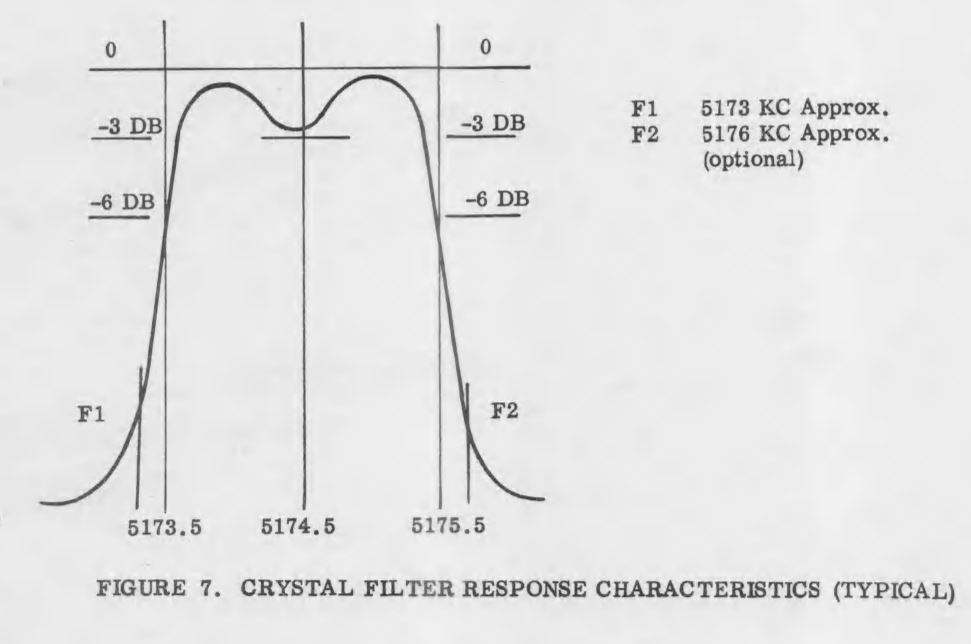
Now, on to the SSB transmitter. The Swan 240 dual crystal lattice filter from the early 1960s needs some impedance matching.
In SolderSmoke Podcast #234, I said that I was scrutinizing the filter from the Swan 240 that I had picked up around 1994 in the Dominican Republic. I cannibalized it out in the Azores in the early 2000s and used the parts to build -- among other things -- my first SSB transmitter. I never really focused much attention on the filter that I pulled out of that old rig -- I was just happy that it seemed to work. But I am now older and wiser, and I have some test gear that lets me look at the passband of that filter.
First, take a look at what it is supposed to look like. This is from the manual. Yikes! That passband looks far from flat. I can almost hear homebrewers around the world shrieking in horror and disgust.
Above is a description of the filter, and the schematic, again from the manual.
Here is what my extracted and somewhat re-built filter looked like in my NanoVNA (more shrieking!). The dip in the passband is a lot worse here -- it looks like 10 db vs. 3 db in the manual. This is probably because I'm not even attempting any impedance matching on the filter -- it is just seeing the 50 ohms in and out of the NanoVNA.
Here is my 2002 attempt to rebuild the filter and put it in my SSB transmitter, along with my more recent attempt to flatten the passband. I no longer had the adjustable coil L8, so I made my own coil based on guidance from Ben Vester W3TLN's January 1959 QST article on "Surplus-Crystal High-Frequency Filters." (Ben had an early influence on Pete Juliano's tube-rig designs.) In the picture above I have 1k pots between the filter and the input and the output of the NanoVNA, as described by Nick M0NTV.
Adjusting the 1 k pots, I could smooth out the passband quite a bit. Measuring the pots and adding the 50 ohms of the NanoVNA, it looks to me like this filter is smoother with about 280 ohms at the input and output. I may build two matching networks or some transformers. Some TIAs may also be needed.
(Why the T/R diodes in the BITX 20 amplifiers?) National Receiver.
Bill's Bench Farhan's Talk to RSGB got me thinking of VHF 2 meter AM. 2 meter Benton Harbor lunchbox madness. SuperRegens Super Strange. I broke my Maplin AF Sig Gen in the process. Fixed it. Playing with MMMRX again. Put in 6 kHz ceramic filter. Sounds great SSB and AM. Swept IF with noise, TinySA, and NanoVNA. Need better noise gen. Mod to listen with TinySA (on blog). Thinking of 17 meter /12 meter Dual-Bander IF around 21.4, VFO around 3.41 Mhz. Thoughts? Sweeping double half lattice filter from Swan 240. UGLY.
MAILBAG: --- ROOTS OF MAILBAG: Radio Moscow, Havana Cuba, HCJB, others. -- Thomas K4SWL of the SWL Post: Could have been worse! Stairbag?
-- MY NOVICE LOG -- Heard back from ex-WN2RTH ex-WN2FLK ex-WB2RKK. -- Drew N7DA worked Wes W7ZOI in Sweepstakes. FB. -- Peter VK2EMU The movie Frequency and the Magic of Heathkits. Good, but not that good! -- Thomas KK6AHT! Our old friend. Minima! Now has a young son! FB -- Chuck WA7ZZE Saw QST profile. Sympathizes with Two-er trouble. -- Tim M0CZP. Spell corrector. Vatican Diodes. Infallible! -- Ramakrishnan VU3RDD Working on a NORCAL and a noise cancellation arrangement. -- Skip NC9O said I was 40 Hz off on 17. But he had a reason to KNOW! -- Steve K9NVD Glad he's a listener. -- Bob KY3R Novice Nostalgia. Should he use 75 watt bulb for dummy load? Yes! -- Todd K7TFC Video about why solder smoke goes into the face. -- Anthony VU3JVX Homebrew Antuino. I ask for help in moving freq to 450 kHz. -- Jack NG2E Building Pete's DC RX. -- Scott WA9WFA HBR-13 and MMMRX. -- Stephen 2E0FXZ also got a FT-101 VFO. -- Bob K7ZB on the air with 56 mW and a big antenna. -- Dean AC9JQ Retired. -- Allan WA9IRS Right to Repair update. -- Farhan Invited us to Lamakaan ARC, Dec 11 or 12. Will be on QO100 Satellite Live!
-- Many suggestions about my Apollo 11 Time Capsule. Still looking for ideas.
Happy Thanksgiving to all who celebrate this holiday!
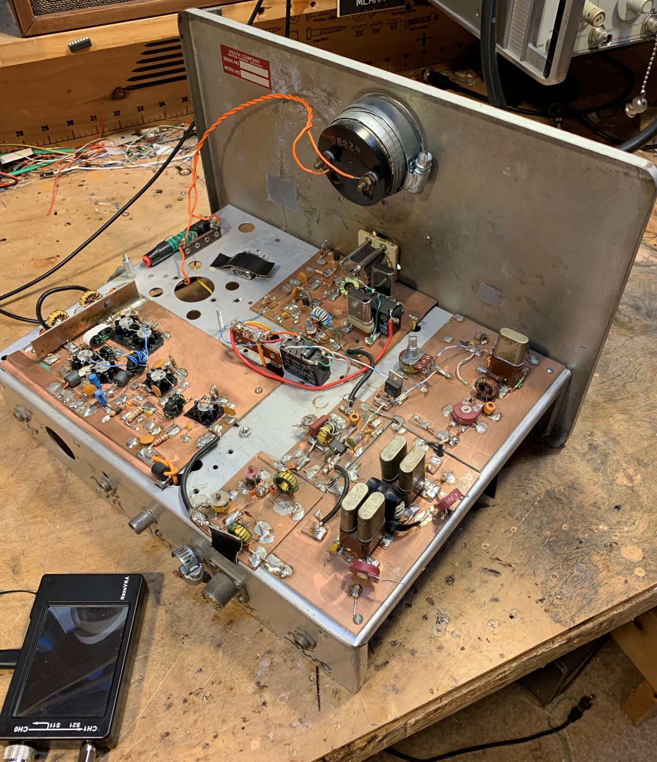
I built this receiver back in 1998, but I continue to have fun tinkering with it. I wrote an article about it for "Electric Radio" magazine (Number 115). One of the major shortcomings was the crystal filter that Lew McCoy prescribed. It was very difficult to get 455 kHz crystals to work well as filters. At various times I've had all kinds of replacements in there in place of Lew's filter: a 455 kHz IF can, a Toyo CM-5 hybrid ceramic filter, a fancy Millen high Q IF transformer. None of them really worked well.
Recently I put a little +/- 3 kHz ceramic filter in there. This is a 6 kHz wide filter at around 455 kHz. I think it works really well. Above you can see the receiver in action. I use it with a little powered computer AF amplified speaker -- I just don't like headphones.
The latest filter mod with the 6 kHz ceramic filter is shown above.
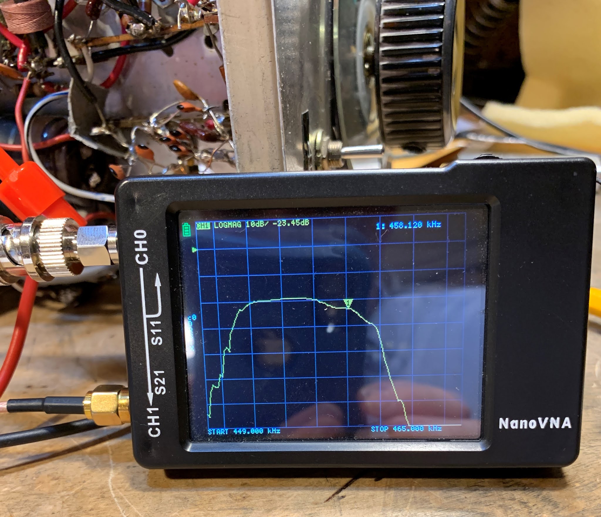
Above you can see what the whole 455 kHz filter and transformer passband looks like. The input was through a 2k resistor placed between the .001 uF cap and the filter. The output was also through a 2k resistor placed at the top of the secondary of T1. (So don't pay any attention to the insertion loss.)
The NanoVNA is displaying 2 kHz per division. I put the BFO at 451 kHz. This results is excellent opposite sideband rejection. The filter is really too wide for SSB, but it is about perfect for AM, which I listen to quite often on both 75 and 40. SSB and AM both sound quite good. Check out the video above.
It is kind of amazing what can be done with just three 6U8 tubes.
There are many previous SolderSmoke blog posts about the Mate for the Mighty Midget Receiver here:
A few days ago I put up a blog post about using a noise generator (in my case my cheap FeelTech sig generator) and my TinySA spectrum analyzer to look at the passband of a crystal filter. I was using the 9 MHz filter used by Dean KK4DAS and the Vienna Wireless Makers Group. The idea is simple: insert broadband noise into the input. The filter should pass more of the noise that falls within its passband. The TinySA should let you see this. At first, I was pleased that I could clearly see the passband. I thought I had succeeded. See above.
But I was bothered by something. Look at that bump in the passband. It should be close to flat across the top.
I decided to take a look at the same filter with my NanoVNA. Here I was not using a noise generator. The NanoVNA sweeps the filter using and looks at output in the Log-Mag mode. Here is what it looked like (below):
That was much better. But why the difference? Tony Fishpool G4WIF suggested that my noise source might not be putting out noise at the same level on all frequencies. I took at look at the noise output of the FeelTech sig gen in the range of the filter passband (with some above and below frequencies for reference) and I found that the flatness of this noise depended a lot on what frequency I had the sig gen set to. I tuned it around a bit until I found a setting that produced a flat noise output in the desired frequency range. Then I went back and swept the filter with the noise and the TinySA again. Here is what it looked like with the "flat" noise:
Better, I think. Closer to the passband displayed by the NanoVNA.
Tony points out that these Chinese sig gens don't really put out random noise -- they give us predictable noise. Dean said "Predictable Noise" would be a good name for a rock group. I said they could open for my favorite: "The Ceramic Spurs."
It is really simple. I had one of the +/- 3kHz (6 kHz wide) 455HT filters on hand. The spec sheets call for 2000 ohms at both ends, but looking at the schematic it appeared that I already had high impedance on both sides of the filter. I put a .001 uF cap on the input side to keep the DC voltage off the filter (see above and below). This capacitor allows us to avoid the dreaded problem of electro-migration that is so nicely described by SV8YM here:
Tasos also provides a good description of the innards of those little black boxes that contain ceramic filters.
Once you get the filter in your receiver, you have to carefully place the BFO signal in relation to the filter passband. I have trouble properly sweeping 455 kHz filters -- my HP8640B will not go that low. Nor will my Antuino (I need to modify the code -- someone help me please). I know the NanoVNA will do the job, but I just couldn't seem to get it to work. So I went "old-school" and manually swept the filter using my FeelTech sig gen and my Rigol scope. This gave me a rough idea of where the passband was. I put the BFO on the low end of the filter passband, at 451 kHz.
With this filter the MMM RX has become a real asset. The 6 kHz bandwidth allows for nice reception of both SSB signals and AM sigs. I may try to use one of the +/- 2 kHz filters (4 KHz wide), but so far I have not been able to find a source for this part.
Featuring a guitar intro by Pete "Bluesman" Juliano, playing his own composition: "Juliano Blues."
Upcoming GQRP convention and the N6QW rig Frank Jones and the FMLA -- Possible Victory? IBEW Stickers:NASA,
Johns Hopkins APL.... Cycle 25 Lookin Better Today:SFI 93SN 47 Pete's Bench: Toobular! A Tube Transmitter SR-160 Simple SSB rigs around the world! KI7NSS's Pacific 40 Bill's Bench The Mythbuster and the Struggle Against the Urban Legend W2EWL's Cheap and Easy SSB W4IMP's IMP. Articles in ER by Jim Musgrove K5BZH and Jim
Hanlon W8KGI The Spirit of Homebrew SSB. From Electric Radio K5BZH
December 1991 Reduced Front End Gain on the DIGITIA Back on 17!HP3SS
sells HBR receiver to Joe Walsh Maybe another Moxon? SHAMELESS COMMERCE DIVISION Test Gear NanoVNA -- Alan W2AEW helped solve mystery of why NanoVNA
not providing accurate readout of circuit impedance.Over driving.Need attenuator. TinySA -- Limited Resolution Bandwidth.But you can listen with it!See video on blog. MAILBAG -- Google Feedburner to end e-mails from the blog :-( -- Paul VK3HN -- TIA AGC? Farhan and Paul looking into options -- Ciprian's Romanian Mighty Mite -- Dino KL0S SolderSmoke GIF and graphical presentation on
sideband inversion -- Allison KB1GMX helped me on 24 volts to IRF 510 issue. -- Dave K8WPE Wabi Sabi and Martha Stewart. And thanks for
parts!40673s! -- Steve N8NM building a 17 meter rig with 22.1184 crystals in
a SuperVXO and a 4 MHz filter. -- Dean KK4DAS restoring an old Zenith.One hand behind your back OM. -- Pete Eaton debating SSB or DSB for 17.Go DSB Pete! -- Richard KN7FSZ a FB HBer.Asked about my solid-stating of Galaxy V VFO. -- Walter KA4KXX on benefits of no-tune BP filters like
Farhan'sFB. -- Jack 5B4APL on Time Crystals and Homebrewing in the 4th
dimension.FB OM! -- Moses K8TIY listens to the podcast with his young son
Robert.Crank it in Robert! -- Farhan and the SBitx on Hack-A-Day -- Also Tom's receiver from junked satellite rig on Hack-A-Day -- Todd K7TFC sent in beautiful message about the spirit of
homebrewing. On the blog. -- Grayson KJ7UM was on Ham Radio Workbench with George Zaf -- AAron K5ATG running a uBitx with ahomebrew tuner and antenna.Hope I can work him -- Heard Mike WA3O last night on 40 DIGITIA.Water cooled amplifier
That would have been a very different movie. And I don't think the box office results would have been favorable. That's PH2LB's "pleasure room" (shack). He has a good blog focused on homebrew:
Alan Wolke W2AEW is a true wizard. We are all lucky to be interested in homebrew radio at the same time that he is sharing his knowledge and wisdom via YouTube.
The ability of the NanoVNA to measure circuit impedances is, in my mind, one of its most valuable features. With this, we can MEASURE input and output impedances. We can put bits and pieces of circuitry together without wondering whether or not we were introducing impedance mismatches.
But I had trouble getting good NanoVNA impedance readings on my TIA amps. I wrote to Alan about this and he pledged to make a video about how to do it right. That video was posted to YouTube today (see above).
Not only did I learn how to get a good impedance reading, I really learned a lot by just watching Alan move around through the various NanoVNA screens. I want to be able to do that too! I want to monitor the Smith Chart, and gain, and SWR, all at the same time. Yes I do! I also now realize that I have to order a bunch of those cool PC board SMA female connectors from Bezos.
This is a 5.2 MHz crystal filter. I used the G3UUR method for determining the crystal's motional parameters. I then used Dishal and AADE software to design a 10 pole Cohn Min-Loss filter. I tested the bandwidth with an Antuino Scalar Network analyzer (thanks Farhan!) and a NanoVNA. I found the passband to be a bit tight for SSB, so I replaced the capacitors with caps of a slightly lower value -- this broadened the passband. It is still a bit tight, but the SSB audio -- while not enhanced or Hi-Fi -- sounds fine.
Passband filter shape as seen in the Antuino and in the NanoVNA. The -20 db line in the Antuino actually corresponds to no loss.
The schematic provided by the AADE software. Dishal software may have come up with better, more correct values for the capacitors.
The passband as predicted by AADE. Skirts so nearly vertical as to strike fear in the hearts of SDR owners!
Filter under construction -- waiting for the caps from Mouser.
First scan with the NanoVNA. Insertion loss looks very high but that is only because I am terminating the filter with resistors -- I just wanted to see the passband shape.
Tony G4WIF sent me this video from Nick M0NTV. It presents Nick's latest Bread Bin project -- "The Optimizer."
-- I really like the Bread Box enclosures. And leaving the b and the d on the box is just brilliant. These letters now stand for BiDirectional! They even appear symmetrical. TRGHS!
-- The switch for a tuning tone is a great idea. I still have to plug my Maplin AF sig gen into the mic jack to do this. FB.
-- I too have the connector on the back for keying the outboard linear amplifier. (Shhh! Don't tell G-QRP!)
-- As for the bidirectional TIA amps. I'm really glad that someone else is using these circuits. Wes's article came out in 2009 and concluded with a call for someone to build a complete rig with these circuits. I wonder how many rigs like this have been made. It is a great circuit. One thing I would suggest for Nick: Wes's article points out that you CAN have higher gain in one direction than you have in the other. Just use resistor values in the chart provided in the 2009 article. You could have an amp with 15 db in the transmit direction and 24 db in the receive direction. BTW: I have been getting a lot of help from Alan W2AEW and Farhan VU2ESE on how to use the NanoVNA to confirm the input and output impedances on solid state amplifiers.
-- For many years I had the same map of the Moon in my shack. I hope that map makes it to the new house Nick.
-- Finally, I was really surprised to hear EI0CL calling CQ during Nick's demo of the receiver. That is Michael Higgins out in Galway. Michael was one of my regular contacts when I was out in the Azores. He is a truly amazing guy. He is mentioned frequently in my "SolderSmoke -- Global Adventures in Wireless Electronics" book. TRGHS.
I continue to work on the "Mythbuster" rig, but I am taking it slow, trying to learn something from each stage. I'm especially trying to master the used of the great test gear that has arrived in my shack in recent years: The Antuino, the NanoVNA, and the TinySA.
Above you can see the passband of the 10 pole crystal filter as measured across the 50 ohm terminations on the filter. I use simple FT37-43 transformers to match the filter impedance down to 50 ohms. I used the Antuino first -- it scanned the passband and held the image on its screen. I then disconnected the Antuino and connected the NanoVNA. So in this shot you can see the passband on both devices.
You will notice that the Antuino says there is a 20db insertion loss. That's only because in the Antuino 20db is really 0 db loss. I think the NanoVNA gives a more accurate insertion loss reading -- about 3-5 db. The cool thing is how similar the shapes of the passband are.
It is a great day my friends. G-QRP has posted on YouTube the presentations made at their 2020 convention. TRGHS! Above you can see the awesome FB contribution of Pete Juliano N6QW. I watched it live on Zoom, but have been waiting patiently for the opportunity to share it with SolderSmoke readers and listeners.
There are many other great videos of convention presentations on the G-QRP YouTube channel. Here is the link to the channel:
This video is another reminder of how lucky we are to have Alan Wolke W2AEW as a fellow radio amateur, and as a teacher and mentor. In this video, Alan is talking to the Denby Dale Amateur Radio Society in Yorkshire, UK. The first part of his talk is about IMD products, the importance of 3rd order products, and the benefits of attenuation. The second part of the talk (after a few questions) is a look at the NanoVNA, which Alan cites as the "Toy or Tool of the Year." I learned a lot from both portions of the presentation. I now find myself wanting an H4 model of the NanoVNA (bigger screen). Or maybe even an F model. Thanks to Alan, I now know what S21 and S11 means.
Thank you Alan, and thanks to the Denby Dale ARS. 73 Bill
"SolderSmoke -- Global Adventures in Wireless Electronics" is now available as an e-book for Amazon's Kindle.
Here's the site:
http://www.amazon.com/dp/B004V9FIVW
Did you know there’s a new MTR-3B in the works–?
-
A reader reached out to me this morning asking about the Mountain Topper
MTR-3B. It reminded me of a teaser LnR Precision posted earlier this month
in an M...
We’re a garage band, we come from garageland
-
Hi, FastRadioBurst 23 here letting you know of a couple of our shows this
week. On Sunday 28th April 2024 at 0900/1300 hrs UTC on 6160 kHz and then
at 2000...
Power standing wave null… more
-
Power standing wave null? discussed the “Power Standing Wave” concept
unfolding on social media. Already a correspondent has asked if the graphs
given in P...
Trying a $15 70cm transceiver HK-188
-
Peter, VK3YE, recently posted a video of a pair of 433Mhz transceivers he
bought at Aldi for $20. They worked OK but had a number of obvious annoying
probl...
An Inline RF Step Attenuator for QRPp Work
-
I don’t need to explain the attraction of low power operation; if you’re
reading this, the chances are that you are already a convert. I’ve been
operating ...
Using an external clock with the RX-888 (Mk2)
-
*The RX-888 (Mk2) and external clocking*
*Figure 1:*
The RX-888 with external clock input *(right)*
The enable/disable switch is barely
visible behind the...
A 51S-1 Restoration Story
-
I came across my Collins 51S-1 in a big junkyard in Ankara, Turkey around
2012. It was in a pile with a lot of other electronic scrap, probably from
one o...
New QRP Cluster Online From OM0ET and OM6APN
-
By DX EXPLORER
DX EXPLORER
Paul OM0ET and Peter OM6APN recently launched a new cluster dedicated to
QRP operations. Have a look and I hope you will enjoy...
3D Printing The Hadley 114mm Newtonian Telescope
-
Yes, we’re building a 3D Printed Newtonian Telescope called Hadley. It’s
being printed in PETG and in the video below, I give a quick tour. My build
isn’...
3D printed project boxes
-
I have been busy with some other things that have kept me away from
electronics projects for quite a while. Now I can get back to them, but
realize I n...
Daylight Again – An all Analog Radio
-
What’s all this? In 10 seconds, A high performance, 7MHz, 5 watt SSB rig
Draws just 24 mA of current 90 dB dynamic range, 80 dB close-in dynamic
range 3D ...
Adding Enclosure to your sBitx Boards Order
-
The early buyers of the sBitx board set who bought it for $270 USD might
want to also add the enclosure (box) for in the kit. What you will now get
is a f...
Digi-chirp! Digital synthesis of ‘nostalgic’ CW
-
The bottom ends of 80, 40 and 20m are not what they used to be. For
starters, the busiest part is the digital segment where computers talk to
computers – l...
-
A Simple Speech Processor
(For QRP/SSB Homebrew Transceivers )
Over the last few weeks I had been thinking to build a small AF speech
processor to add to...
A New Look for your uBitx!
-
Adding a "Cool Blue" Display to your uBitx!
The standard "green background" with black lettering frequently reminds me
that I suffer from Chronic seasickn...