Just go to http://soldersmoke.com. On that archive page, just click on the blue hyperlinks and your audio player should play that episode.
http://soldersmoke.com
It was great to get a comment from Paul VK3HN -- this led to a re-establishment of contact. Apparently Google knows who I have been e-mailing, so this great video appeared on my YouTube screen. Thanks Google!
-- Great to hear Paul's shout out to Pete Juliano N6QW, and Pete's concept of noodling.
-- Paul's emphasis on testing each stage independently is really important.
-- Wow, ferric chloride! It is great to see someone doing this (instead of just sending Gerber files to China).
-- Books. This reminds me that I have to get Drew Diamond's books.
-- Paul's comment on the usefulness of a general coverage receiver. Right on target Paul.
-- On the test gear, we can now add the TinySA Ultra. And you don't have to win the Lotto!
-- Finally, Paul is absolutely right on the need to constantly update and publish changes to schematics. I am guilty of not doing this. (I hang my head in shame.) This became a problem in our simple High-School receiver project -- I would make changes to circuits and fail to communicate these changes to Dean KK4DAS. Paul's method would have solved this problem.
PA3AKE's passband (on screen) an mine (on NanoVNA)
While I was away in the Dominican Republic (3-9 August 2023), I was thinking about spurs. While there I watched Nick M0NTV's video about mixers. The video was all great, but I was especially taken by the way he used a spectrum analyser to evaluate the output of various mixers. This made me think that I should do the same thing with the output of each of my dual-band BITX rigs.
I was especially worried about the output from my 17-12 rig. The IF is at 21.4 MHz. The VFO runs around 3.5 MHz. So if you add the IF and the carrier oscillator signal you get to 12 meters. If you subtract them you get to 17 meters. But you need some good bandpass filtering to sufficiently knock down the unwanted output from the mixer. And the BP filter should be sufficiently narrow to take out any remnants of the carrier oscillator signal. I had taken the easy way out and had used simple dual-tuned-circuit (DTC) filters. I started to wonder if these simple BP filters would be enough to knock down the 12 meter signal while on 17 and the 17 meter signal while on 12. I pulled out my NanoVNA to look at the passbands:
Here is what the 17 meter DTC filter passband looked like. The cursor is at 29.6 MHz and you can see that near the 12 meter band it is only providing about 21 db of attenuation. That is not enough.
And here is what the 12 meter filter looked like. Here the cursor is at 18.150 Mhz and shows about 25 db of attenuation at this frequency. Again, not enough.
The results are as you would expect: I could see 24.9 MHz signals in the output when I was on 17 meters, and I could see 18 MHz signals in the output when I was on 12 meters. The spurs weren't strong, but they were there. I knew that more robust BP filters would help.
At first I used the circuits prescribed by Martein PA3AKE. He used larger toroidal cores, I used smaller T-50-6 (yellow) cores. The results were very similar. See the first picture on this blog post.
The results were really good. See pictures below. I was using a TinySA with the signal fed through a 50 ohm 30db attenuator. I was putting a 1 kHz signal in to the mic input.
This picture shows the 12 meter output and the now non-existent 17 meter spur. The cursor is at 18.142 MHz:
This picture shows the 17 meter signal and the now non-existent 12 meter spur. The cursor is at 24.993 MHz. We can see some second harmonic signal getting past the LP filter -- I will fix this.
Then Farhan commented on Martien's filters, noting that they are all in the "LSB" configuration. You can see from the charts below how they would be really good when you are trying to use the "difference" output from your mixer while knocking down the sum output, but not vice versa. So I built new USB filters for 12 meters, and for 10 meters in my nee 15-10 rig. I got better results on the two "sum" bands in my rigs (10 and 12 meters)
The improved resolution could be useful -- we may now be able to see the sidebands coming out of a mixer that is producing AF out (as in a DC receiver).
The bigger screen is nice.
Looks like Dean and I will not have to modify our TinySAs for audio out. We will just upgrade to Ultra so we can listen in style to Vatican Radio and Radio Marti.
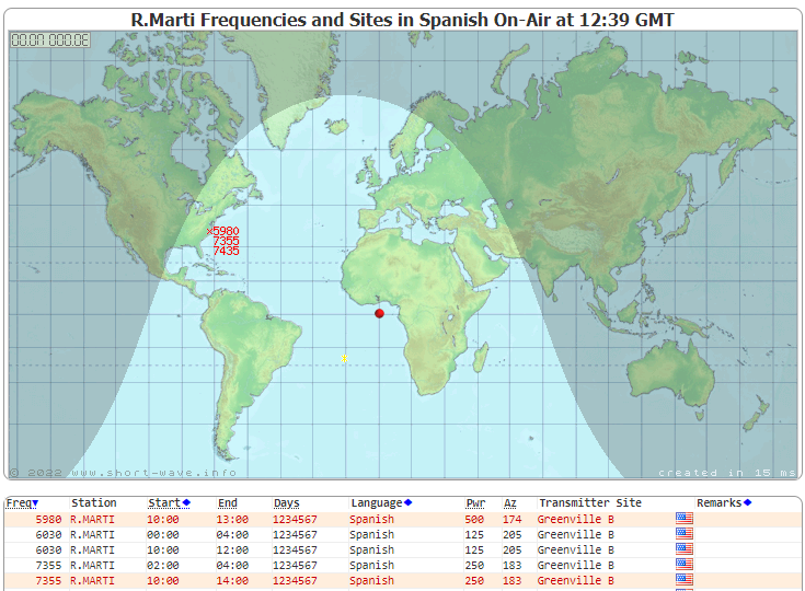
November 18, 2022 1244 UTC. I was using a TinySA spectrum analyzer to look at noise levels on the 40 meter ham radio band. I also wanted to take a look slightly above the band (in frequency) to see Radio Marti at 7355 kHz. As I was doing this I remembered that Vatican Radio was on the air at 7305 kHz from 1230 UTC to 1245 UTC. So was just going to catch the last moments of that day's transmissions. Sure enough, I caught it, and watched it disappear from the TinySA screen. See the video above.
Radio Marti continued on. In the morning we can hear the rooster recordings from that station. We are using it to test how well our homebrew Direct Conversion receivers avoid AM detection. In the video I mistakenly said these two transmitters were on the air with 250 megawatts. The correct power is 250 kilowatts. Both transmit from Greenville NC. I think the signal from Vatican Radio is stronger here because they are using a different antenna pattern -- Radio Marti is aimed at Cuba.
This reminds me of a cool project I have not yet done: modifying the TinySA to allow the user to listen to the station: https://soldersmoke.blogspot.com/2021/10/how-to-listen-with-your-tinysa.html I notice that Dean KK4DAS (my colleague in DC receiver design) was the only commenter on the blog post describing the TinySA mod. TRGHS. We need to to do this.
Here are the reports showing when Vatican Radio and Radio Marti were on the air on November 18, 2022:
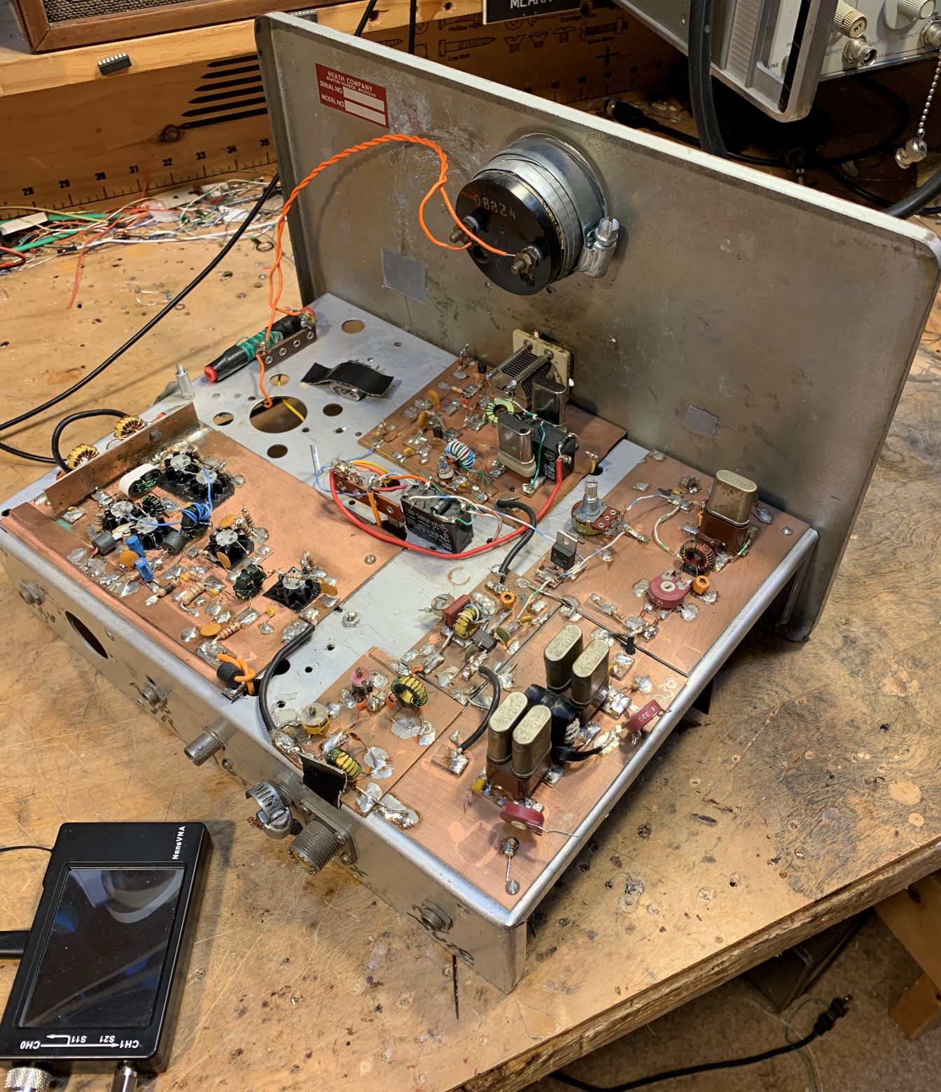
Dennis WC8C is the event coordinator for the radio club in Michigan that I recently spoke with. He mentioned to me that he was working on a homebrew 6 meter rig. FB Dennis. I see lots of tribal wisdom in your approach, especially in your decision to do this in a stage-by-stage modular form.
Dennis's rig is obviously a work in progress, so if anyone out there has any helpful hints (especially on the carrier suppression and on the testing for spurs and splatter) please share them with him via e-mail or blog post.
This is my 6 Meter homebrew transceiver, currently work in
progress.It is a single conversion
super –heterodyne design.I constructed
each stage independently with SMA connectors.This is so I can re-make sections as needed, and will allow me in the
future to swap sections to experiment with alternate designs.The VFO and BFO are controlled using a SI5351
with an Arduino micro controller.I
currently have separate SI5351 modules for VFO and BFO because I suspected
issues with cross-talk.These issues may
not actually be real, so once I am happy with the performance, I will test
again with just one module to see if it is OK.The Power Amp is still on the to-do list, so output is well under 0 DBm
The Blue boards were designed by me and ordered
on-line.The other boards I etched
myself.Construction is mostly surface
mount because I find it easier than drilling all the holes.SMD components are mostly 805 and 1206 size.
Transistors are SOT23.
The Band Pass filter is a 5 coil design made with air-core
inductors.
3 bi-directional termination insensitive (TIA) amps are used
(blue boards).Total RX gain is about
44db.Total TX gain is about 16db.Each board has its own independent RX/TX
switching circuitry (mosfet based) and is fed with +12.5, GND, and RX/TX logic
signal from the Arduino (3V logic and up will work)
The Mixer and modulator are both Diode Ring mixers.
The 12 MHz SSB filter is a crystal ladder filter similar to
the one used in the uBitx.
The Mic and audio pre-amp (also a blue board) is made on a
modified TIA amp board.I had 10 of
these boards made, and the needed circuitry was largely the same, so I modified
the board with a rotary tool and jumpers.
The Audio amp is a PAM8403 module and drives a headset.I did make some modifications to the module so
it runs in-spec and to eliminate the power on audio pop.
The challenges I have been having are mostly related to
spurs, splatter, carrier suppression and TX audio quality.I have been gradually tweaking these things
to improve operation before I start on a power amp.My IF is 12 MHZ, and I was using the LSB side
of the crystal filter because it is sharper (VFO 62 – 66 MHz) but have recently
changed over to the USB side of the filter (VFO 38 – 42 MHz).This eliminated the spurs I was seeing near the
pass band.I still need to make some
adjustments to the crystal filter as it is too broad.
I still have some splatter and audio quality seems low, but
I am starting to doubt my test setup.I
see the splatter on the RTL SDR, but I don’t see it on the Tiny SA.The spatter happens at ~160 KHz
intervals.I am hoping to find someone
local with a better spectrum analyzer to help me verify if it is the rig or my
SDR dongle/test setup.
The modules to the side of the picture are my
rejects/experiments.The one covered in
copper shows how I eventually will shield all the modules.I 3D printed a cover for the board, when
wrapped it with copper tape, soldered to the bottom ground plane.The one shown is a diode ring modulator.For some unknown reason the carrier
suppression is rather poor.I had
previously made a junk-box modulator that had much better carrier
suppression.I don’t know why it is
better than the one I more carefully made for the radio, but until I figure it
out, I am using the junk box version.The junk box modulator uses unmatched schottkey diodes, whereas the
“final” one uses a 4 diode SMD package because I wanted them matched – I
thought this would be better, but maybe not.
First, thanks to all who sent in suggestions. They came in literally from around the world, and this is a demonstration of the IBEW in action. I used or at least tried all of them. They were all good ideas.
Following Vasily Ivananeko's pseudonymous suggestion I rebuilt the carrier oscillator (apologies to G3YCC). I used the carrier oscillator/buffer circuit from Farhan's BITX20.
Henk PA0EME said I should look at the signal level at the input ports of the NE602 mixer. Henk was right --- the VXO input was far too high. I lowered it, but the problem persisted.
At first, I thought that the spur in question was so small that it would not show up on the air. I could not see it in the TX output using my TinySA spectrum analyzer. That was good news and bad news: Good that it was not showing up on the air, bad that I could not see it in the TinySA and use that image in the exorcism.
At first I thought that the spur was being caused by the 10th harmonic of the carrier oscillator and the third harmonic of the VXO. This seemed to fit. So, following VK3YE's sage advice, I built a little 69 MHz series LC trap (using a coil sent by AA1TJ, on a board CNC'd by Pete N6QW). That trap succeeded spectacularly in crushing the 10 harmonic. Look at these before and after shots on the TinySA:
Before Trap
After Trap
Spectacular right? But guess what? The problem was still there.
I scrutinized the situation once more. I realized that the spur would be more visible if I put the TinySA on the input of the transmitter's PA (a JBOT amp designed by Farhan) as opposed to putting it on the output. Watching the spur and the needed signal move in the TinySA as I tuned the VXO, I realized that they were moving in opposite directions. This indicated that the spur was the result of a carrier oscillator harmonic MINUS a VXO-generated frequency (as the VXO frequency increased, the spur frequency decreased). Looking at my EXCEL spread sheet, I could see it: 8th harmonic of the carrier oscillator MINUS the main output of the VXO.
To confirm this, I plugged the values into W7ZOI's Spurtune program. Yes, the spur popped up and moved as predicted.
For further confirmation I shut down the carrier oscillator by pulling the crystal from the socket, and then just clipped in a 5.176 MHz signal from my HP-8640B signal generator (thanks KB3SII and W2DAB). Boom! On the TinySA, the spur disappeared. Now I at least knew what the problem was: a harmonic from the carrier oscillator.
Following good troubleshooting practice, I turned off the gear and went to bed. When I woke up, an idea came to me: Before launching into a lot of filtering and shielding, just try running the carrier oscillator at a lower voltage, seeing if doing so might reduce the harmonic output. I disconnected the carrier oscillator board from the main supply and clipped in a variable voltage bench supply. Watching the signal on my TinySA, I watched as the spur completely disappeared as I reduced the voltage from around 13V to 10V (see video above). The main signal frequency level did not change much. I tested this by listening for the hated extra tones. They were gone. Exorcised.
Key lessons:
-- Spur problems are difficult to troubleshoot. Armstrong's superhet architecture is, of course, great, but this is definitely one of the pitfalls. Single conversion makes life easier. IF selection is very important. Choose wisely!
-- When looking at the TinySA as you tune the rig, pay attention to which way the spur is moving. This provides an important clue regarding the combination of harmonic you are dealing with.
-- The TinySA is a very useful tool. It seems like it is easier to use than the NanoVNA (which is also a fantastic tool).
-- It can be fun and rewarding to re-visit old projects. In the years between original construction and the re-look, new test gear has become available, and the skill and experience of the builder has improved. So problems that once seemed insurmountable become fix-able.
-- Thinking through a problem and thinking about possible solutions is very important. It pays to step away from the bench to think and rest. Rome wasn't built in a day. Here's a rough block diagram that I drew up (noodled!) while trying to figure out this problem:
(Why the T/R diodes in the BITX 20 amplifiers?) National Receiver.
Bill's Bench Farhan's Talk to RSGB got me thinking of VHF 2 meter AM. 2 meter Benton Harbor lunchbox madness. SuperRegens Super Strange. I broke my Maplin AF Sig Gen in the process. Fixed it. Playing with MMMRX again. Put in 6 kHz ceramic filter. Sounds great SSB and AM. Swept IF with noise, TinySA, and NanoVNA. Need better noise gen. Mod to listen with TinySA (on blog). Thinking of 17 meter /12 meter Dual-Bander IF around 21.4, VFO around 3.41 Mhz. Thoughts? Sweeping double half lattice filter from Swan 240. UGLY.
MAILBAG: --- ROOTS OF MAILBAG: Radio Moscow, Havana Cuba, HCJB, others. -- Thomas K4SWL of the SWL Post: Could have been worse! Stairbag?
-- MY NOVICE LOG -- Heard back from ex-WN2RTH ex-WN2FLK ex-WB2RKK. -- Drew N7DA worked Wes W7ZOI in Sweepstakes. FB. -- Peter VK2EMU The movie Frequency and the Magic of Heathkits. Good, but not that good! -- Thomas KK6AHT! Our old friend. Minima! Now has a young son! FB -- Chuck WA7ZZE Saw QST profile. Sympathizes with Two-er trouble. -- Tim M0CZP. Spell corrector. Vatican Diodes. Infallible! -- Ramakrishnan VU3RDD Working on a NORCAL and a noise cancellation arrangement. -- Skip NC9O said I was 40 Hz off on 17. But he had a reason to KNOW! -- Steve K9NVD Glad he's a listener. -- Bob KY3R Novice Nostalgia. Should he use 75 watt bulb for dummy load? Yes! -- Todd K7TFC Video about why solder smoke goes into the face. -- Anthony VU3JVX Homebrew Antuino. I ask for help in moving freq to 450 kHz. -- Jack NG2E Building Pete's DC RX. -- Scott WA9WFA HBR-13 and MMMRX. -- Stephen 2E0FXZ also got a FT-101 VFO. -- Bob K7ZB on the air with 56 mW and a big antenna. -- Dean AC9JQ Retired. -- Allan WA9IRS Right to Repair update. -- Farhan Invited us to Lamakaan ARC, Dec 11 or 12. Will be on QO100 Satellite Live!
-- Many suggestions about my Apollo 11 Time Capsule. Still looking for ideas.
Happy Thanksgiving to all who celebrate this holiday!
A few days ago I put up a blog post about using a noise generator (in my case my cheap FeelTech sig generator) and my TinySA spectrum analyzer to look at the passband of a crystal filter. I was using the 9 MHz filter used by Dean KK4DAS and the Vienna Wireless Makers Group. The idea is simple: insert broadband noise into the input. The filter should pass more of the noise that falls within its passband. The TinySA should let you see this. At first, I was pleased that I could clearly see the passband. I thought I had succeeded. See above.
But I was bothered by something. Look at that bump in the passband. It should be close to flat across the top.
I decided to take a look at the same filter with my NanoVNA. Here I was not using a noise generator. The NanoVNA sweeps the filter using and looks at output in the Log-Mag mode. Here is what it looked like (below):
That was much better. But why the difference? Tony Fishpool G4WIF suggested that my noise source might not be putting out noise at the same level on all frequencies. I took at look at the noise output of the FeelTech sig gen in the range of the filter passband (with some above and below frequencies for reference) and I found that the flatness of this noise depended a lot on what frequency I had the sig gen set to. I tuned it around a bit until I found a setting that produced a flat noise output in the desired frequency range. Then I went back and swept the filter with the noise and the TinySA again. Here is what it looked like with the "flat" noise:
Better, I think. Closer to the passband displayed by the NanoVNA.
Tony points out that these Chinese sig gens don't really put out random noise -- they give us predictable noise. Dean said "Predictable Noise" would be a good name for a rock group. I said they could open for my favorite: "The Ceramic Spurs."
I've been meaning to try this for a long time. Years ago Tony Fishpool and Graham Firth wrote about using a noise generator and a spectrum analyzer to sweep the bandpass of a filter. The idea here is to send very broadband noise into a filter, and then use a spectrum analyzer to see which frequencies make it through.
I thought about building a noise generator like the one in Tony and Graham's book, but then it occurred to me that probably had one sitting on my bench. Sure enough, a look at the manual for my cheap FeelTech function generator revealed that PRESETS 3 and 8 are noise generators. I quickly pulled out a 9 MHz filter that Dean KK4DAS had given me, put the noise into one end and the TinySA on the other end. Bob was quickly my uncle. See above.
More recently Tony G4WIF built a comb generator as a noise source:
We don't get many chances to do hardware work on a piece of gear like the TinySA, but here we have one. I mentioned this a while back: Not only will the TinySA display the signals it detects, but it will also allow us to listen to these signals. Very cool. I am going to do this.
The TinySA has some very cool capabilities, and this short intro video provides a good sense of what it can do.
I am learning how to use the TinySA so that I can check the output of my Mythbuster transceiver (I now have the first portion of the transmitter working.) I tried to use the TinySA to check the carrier and opposite sideband suppression on my new Mythbuster transceiver, but I think the max Resolution Bandwidth (3 kHz) is too high for me to do this. Please let me know if I am missing something. That would have been a very useful capability.
It also functions as a signal generator that also provides AM and FM modulated signals. You can also have a waterfall on the spectrum display. Very nice.
I have not yet figured out how to listen to the signals. This is one of Erik's videos -- it looks like you have to solder in a connection for audio out.
"SolderSmoke -- Global Adventures in Wireless Electronics" is now available as an e-book for Amazon's Kindle.
Here's the site:
http://www.amazon.com/dp/B004V9FIVW
We’re a garage band, we come from garageland
-
Hi, FastRadioBurst 23 here letting you know of a couple of our shows this
week. On Sunday 28th April 2024 at 0900/1300 hrs UTC on 6160 kHz and then
at 2000...
Military Radios in the Wild
-
Was recently running the MUTT in the field on RTTY and voice, posted a
video over on the tube at:
https://www.youtube.com/watch?v=kLxH3j8mzYs
Will have th...
Power standing wave null… more
-
Power standing wave null? discussed the “Power Standing Wave” concept
unfolding on social media. Already a correspondent has asked if the graphs
given in P...
April 25, 2024. Meter Magic
-
At times we need to include some form of metering in our homebrew rigs. No,
we will not be installing a Nano VNA in a transmitter. But often a current
mete...
Trying a $15 70cm transceiver HK-188
-
Peter, VK3YE, recently posted a video of a pair of 433Mhz transceivers he
bought at Aldi for $20. They worked OK but had a number of obvious annoying
probl...
An Inline RF Step Attenuator for QRPp Work
-
I don’t need to explain the attraction of low power operation; if you’re
reading this, the chances are that you are already a convert. I’ve been
operating ...
Using an external clock with the RX-888 (Mk2)
-
*The RX-888 (Mk2) and external clocking*
*Figure 1:*
The RX-888 with external clock input *(right)*
The enable/disable switch is barely
visible behind the...
A 51S-1 Restoration Story
-
I came across my Collins 51S-1 in a big junkyard in Ankara, Turkey around
2012. It was in a pile with a lot of other electronic scrap, probably from
one o...
New QRP Cluster Online From OM0ET and OM6APN
-
By DX EXPLORER
DX EXPLORER
Paul OM0ET and Peter OM6APN recently launched a new cluster dedicated to
QRP operations. Have a look and I hope you will enjoy...
3D Printing The Hadley 114mm Newtonian Telescope
-
Yes, we’re building a 3D Printed Newtonian Telescope called Hadley. It’s
being printed in PETG and in the video below, I give a quick tour. My build
isn’...
3D printed project boxes
-
I have been busy with some other things that have kept me away from
electronics projects for quite a while. Now I can get back to them, but
realize I n...
Daylight Again – An all Analog Radio
-
What’s all this? In 10 seconds, A high performance, 7MHz, 5 watt SSB rig
Draws just 24 mA of current 90 dB dynamic range, 80 dB close-in dynamic
range 3D ...
Adding Enclosure to your sBitx Boards Order
-
The early buyers of the sBitx board set who bought it for $270 USD might
want to also add the enclosure (box) for in the kit. What you will now get
is a f...
Digi-chirp! Digital synthesis of ‘nostalgic’ CW
-
The bottom ends of 80, 40 and 20m are not what they used to be. For
starters, the busiest part is the digital segment where computers talk to
computers – l...
-
A Simple Speech Processor
(For QRP/SSB Homebrew Transceivers )
Over the last few weeks I had been thinking to build a small AF speech
processor to add to...
A New Look for your uBitx!
-
Adding a "Cool Blue" Display to your uBitx!
The standard "green background" with black lettering frequently reminds me
that I suffer from Chronic seasickn...