
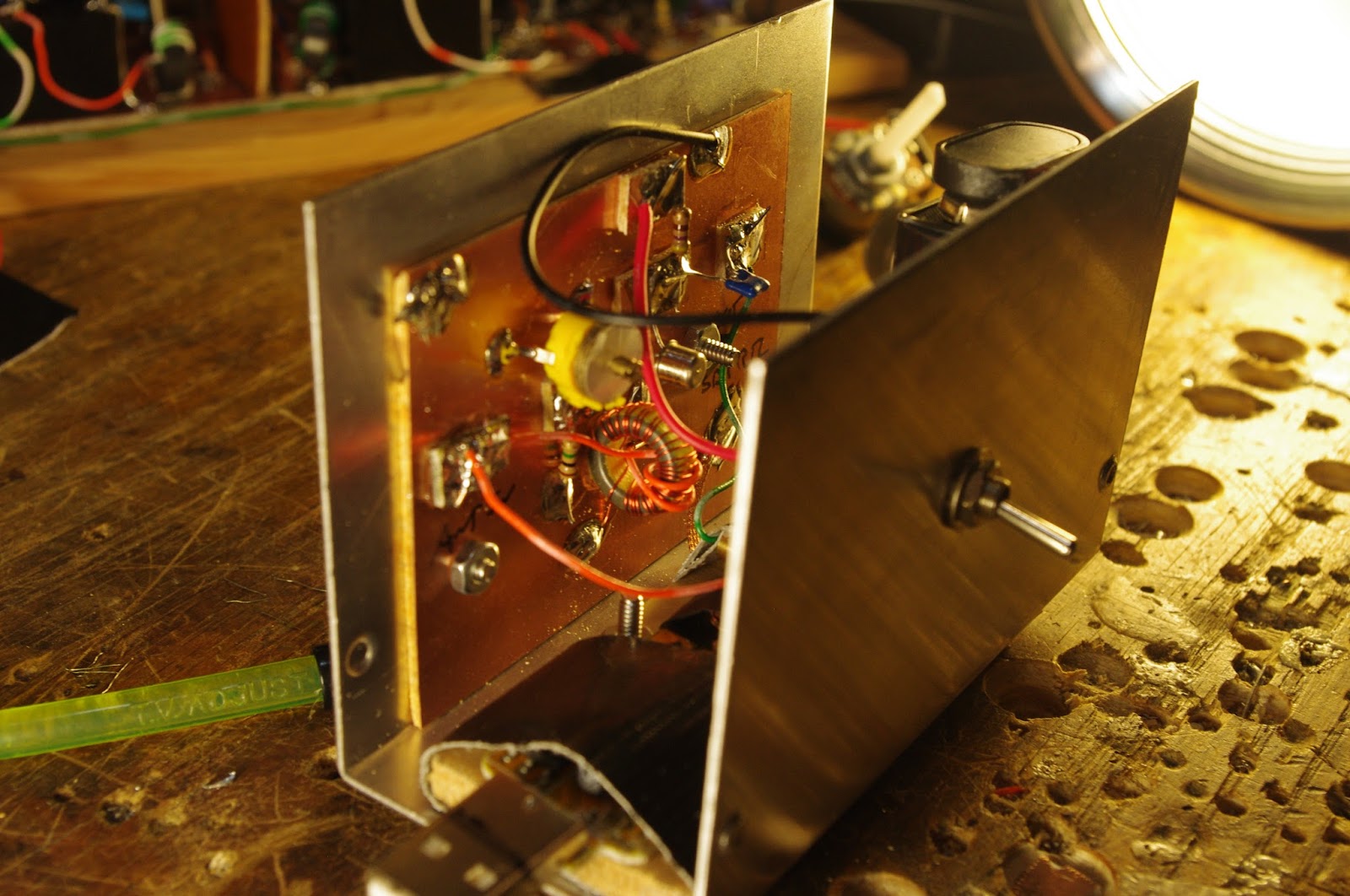
Here it is. Very simple. I used an obsolete 40673 dual gate MOSFET. I didn't need both gates so I just soldered them together. You could probably substitute an easily obtained MPF-102 JFET. The capacitors and the coil in in the gate circuit form a parallel LC filter circuit that resonates in the 40 meter ham band. The 1 Megohm resistor maintains a very high impedance for the LC circuit, helping to maintain circuit Q (sharp response). It also drains off any charge that builds up on the gates. For the antenna input I just put 2 turns on the 4.5uH coil -- this too helps maintain LC filter response. The 470 ohm resistor serves as the load and limits quiescent current through the MOSFET. It should pull about 19 milliamps -- with a 9V battery that should give you around 26 hours of listening time between battery changes. That's fine with me -- I don't use this thing that much.
Realize that I'm using this with an RTL-SDR dongle that has been given the familiar modification that allows it to use direct sampling in the HF bands. Some ideas here:
and here
and here

Nice write up Bill. I used the up-converter method on my SDR dongle. SA/NE602/612 with a 50Mhz oscillator. I know how you dislike IC's but the NE602 provides some gain along with the up conversion. I added a low pass filter of around 30Mhz to suppress the FM band. The dongles work great for a cheap spectrum analyzer. Always a good tool to have in the shack.
ReplyDeleteBill
ReplyDelete19 ma through the 470 ohm load resistor would leave almost nothing on the drain, probably leading to little gain and poor strong signal handling. Are you sure this is what you have?
W3JDR
W3JDR: You are correct. I failed to account for the drop across the MOSFET. Duh. I just took some measurements. There is .96 volts across the 460 ohm resistor, which indicates a little over 2 milliamps quiescent current, right. Wow, that 9V battery is going to last a long time! 73 Bill
ReplyDeleteDean: I hear ya, but the thought of up converting just so the dongle could down convert somehow didn't appeal to me. That would kind of make it a dual conversion dongle! Also, when you do that you have to fiddle with the software to get it to display the proper frequency, right? No such trouble with direct sampling. 73 Bill
ReplyDelete