But until now, I never built one. Recently, Dean KK4DAS and the Vienna Wireless Makers group have been building a Direct Conversion receiver. Their receiver uses an Si5351 as the VFO, but of course Dean and I have decided to try to do things the hard way by building non-digital VFOs. At first we just came to the conclusion that my earlier Ceramic Resonator VFO wasn't much good (it drifted too much). This led us into standard Colpitts and Armstrong VFOs, and the fascinating world of temperature compensation. Then I remembered the Polyakov circuit -- this would allow us to use a 3.5 MHz VFO on the 7 MHz band. Lower frequency VFOs are easier to stabilize, so I started building my first Polyakov receiver. You can see the results (on 40 meters) in the video above.
I started working with a circuit from SPRAT 110 (Spring 2002). Rudi Burse DK2RS built a Polyakov receiver for 80 and 40 that he called the Lauser Plus. (Lauser means "young rascal" or "imp" in German.) For the AF amplifier, I just attached one of those cheap LM386 boards that you can get on the internet. With it, I sometimes use some old Iphone headphones, or an amplified computer speaker.
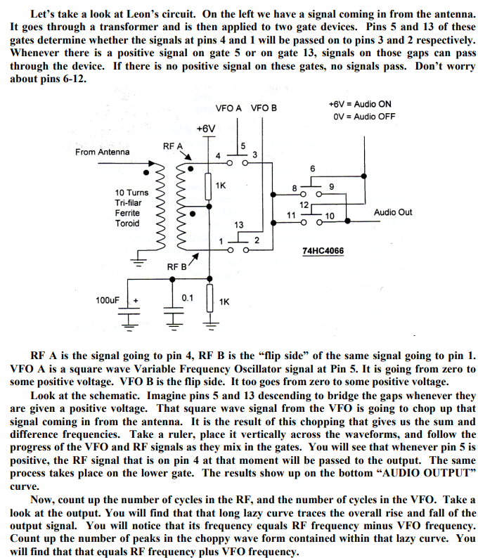
The Polyakov mixer is a "switching mixer." The book excerpt below shows how I understand these circuits. The enlightenment came from the Summer 1999 issue of SPRAT (click on the excerpt for an easier read):
Leon's circuit shows us how a simple switching circuit in which the switches are controlled by the VFO can result in an output that has the sum and difference components. That is the hallmark (and most useful part) of real mixing. Remember -- we say that mixing happens in non-linear circuits when the passage of one signal depends on what is happening with the other signal. A switch is as non-linear as you can get! And that switch is being controlled by the VFO.
In a Direct Conversion receiver we usually run the VFO at the operating frequency. This results in audio just above and just below the operating frequency.
The Polyakov Direct Conversion circuit is a bit different. It has the switches (the diodes) turned on twice each cycle: When the VFO voltage goes to a positive peak, this turns on one of the diodes. When the VFO goes to a negative peak, this turns on the other diode. So in effect the switch is being turned on TWICE each cycle. So with the Polyakov you run the VFO at HALF the operating frequency. For a DC receiver designed to run around 7.060 MHz, you build a VFO at around 3.53 MHz. This has some immediate advantages. My favorite is that it is easier to get a VFO stable at a lower frequency. It is easier to stabilize a VFO at 3.53 MHz than it is at 7.060 MHz.
When you open that SW 1 switch in the Lauser Plus, you no longer have a Polyakov mixer. Now you just have a diode mixer. It will be opening and closing once each cycle at the VFO frequency. DK2RS used this to cover not only the 40 meter band (in Polyakov mode) but also the 80 meter band (in single diode detector mode). That is why DK2RS has that big variable capacitor in the input circuit -- that LC circuit needs to tune all the way down to 3.5 MHz and all the way up to around 7.3 MHz. (I used a coil of about 6.5 uH to do this.)
With just one diode and operating at 80 meters, it works, but not as well as it does in the Polyakov mode on 40. I can pick up 80 meter signals, but in this mode there seems to be more of an "AM breakthrough" problem. "Experimental Methods in RF Design" on page 8.11 describes what is going on (the last sentence is most relevant here):
Here are some very good links with information on the Polyakov receiver:
LA8AK SK: http://www.agder.net/la8ak/ Almost seventeen years after his death he continues to help his fellow radio amateurs through his web sites. TNX OM! FB!
Thanks Bill. My own experiments at HF with subharmonically pumped Schottky diode mixers show clearly that almost every mixer parameter we measure is worse than our classic balanced mixer topologies. Definitely 2LO-RF isolation was better than other unbalanced mixers without the need for a transformer.
I guess it's appealing for low-complexity receiver builders. For zero IF receivers, I like and run my LO at 1/2 RF frequency and then use a doubler -- that's a great advantage for a DC/ Zero-IF receiver and a built-in feature for the subharmonic mixer.
The SH mixer becomes quite appealing at SHF to mm-wave lengths where making a quiet, temp stable LO gets rather expensive and tricky.
Subharmonically pumped mixers can also work at odd integers if the mixer LO/RF drive is balanced and designed to produce distortion that for example, triples the LO frequency. Rohde & Schwarz had a 40.1 GHz spectrum analyzer with one --- and if the LO was 13 GHz while the RF was 39.5 GHz, this gave an IF output of 500 MHz in 1 particular circuit. Really amazing design work. Here's an interesting URL:
The SH mixer has been around for > 4 decades. The oldest SH mixer paper I've got in my library is from Schneider and Snell from 1975. I don't think they invented the SH, but this pair helped popularize it for the world and design work continues today.I've seen optical SH mixers with I/Q outputs in research papers.
Here's the abstract and citation:
Harmonically Pumped Stripline Down-Converter
M. V. Schneider, W. W. Snell Published 1 March 1975 Physics, Engineering IEEE Transactions on Microwave Theory and Techniques
A novel thin-film down-converter which is pumped at a submultiple of the local-oscillator frequency has given a conversion loss which is comparable to the performance of conventional balanced mixers. The converter consists of two stripline filters and two Schottky-barrier diodes which are shunt mounted in a strip transmission line. The conversion loss measured at a signal frequency of 3.5 GHz is 3.2 dB for a pump frequency of 1.7 GHz and 4.9 dB for a pump frequency of 0.85 GHz. The circuit looks attractive for use at millimeter-wave frequencies where stable pump sources with low FM noise are not readily available.
Todd: Thanks for the very thoughtful comment on the Polyakov SH detector. I know it has its limitations, but the simplicity, and the ability to cover two bands made it a must-build for me.
I have it working well on 80 and 40, but I am kind of troubled by what happens when I switch between bands. Let me explain:
The VFO is running 3.5 - 3.6 MHz. When I am on 40 in Polyakov mode, all is well, but when I throw the switch and take one of the two diodes out of the circuit, I can continue to hear an attenuated version of the 40 meter signal. Theoretically I shouldn't be hearing it, right? The signal disappears when I retune the input tank to 80 meters, but it is there when I leave that tank on 40 and switch to just one diode. Why would this be happening? At that point we just have a single diode and an oscillator running at 3.5 3.6 MHz? I checked the level of the VFO's second harmonic -- it is there, but way down: On my Rigol scope in FFT mode the 3.5 MHz signal is at just above 600 mV, while the second harmonic at 7 MHz is below 100 mV.
One possible explanation: RFI. I live in a very intense RF environment: 50,000 watt FM broadcast station on 100.3 FM less than a mile away. I can hear it in the receiver when using just the diode. There is also a 5 kw AM station about 1 mile in the other direction.
So how do you think I am listening to 40 meter CW with just one diode and the VFO on the 80 meter band?
Case #1 = a single diode mixer with a 3.5 MHz LO and a ~7 MHz single-tuned band-pass filter Case #2 = an anti-parallel diode pair with a 3.5 MHz LO and ~ 3.5 MHz single-tuned band-pass filter
In your circuit, both are functioning as “subharmonic mixers”, but case #2 is designed for that purpose and has some phase cancellation of even-order harmonics.
Case#1: • Assuming you are driving the mixer to function as a switch with its open or closed state determined by the polarity of the LO signal – the LO signal will distort with harmonics due to factors including varying input Z caused by the changing current in the diode as the LO moves through its cycle. If you 10X probe the LO signal --- it will appear distorted.
• The input signals will generate harmonics and intermodulation products -- and of will appear at the RF & LO and output ports since there are no balancing 0 to 180-degree LO phases shifts or other tricks to cancel them out. This will include 2LO !!!!
• When you switch to case #1, the single diode is getting greater amplitude compared to case 2. This might translate into even more harmonics, I’m uncertain.
So your 3.5 MHz LO gets doubled to 7 MHz and beats with ~7 MHz Ham band signals to demodulate to audio. The 2LO signal is weaker in amplitude, but still enough to allow detection.
Case #2
“Harmonic mixing” occurs just like in case 1 since our switching diode pair generate lots of harmonic energy. But in this case, we sub-harmonically pump the anti-parallel diodes to reduce/cancel the creation of the even order harmonics (both 2LO and spurious). How well will depend on how well the diodes are matched, layout, etc..
If M + N = the harmonic order of the LO and RF. When M+ N are odd, they will add and pass to the output. However, when N + M are even, they cancel. Diode currents are 180 degrees out phase resulting in the cancellation of the currents at even harmonics. The LO fundamental will get attenuated but shows up input and output ports.


Thanks Bill. My own experiments at HF with subharmonically pumped Schottky diode mixers show clearly that almost every mixer parameter we measure is worse than our classic balanced mixer topologies. Definitely 2LO-RF isolation was better than other unbalanced mixers without the need for a transformer.
ReplyDeleteI guess it's appealing for low-complexity receiver builders. For zero IF receivers, I like and run my LO at 1/2 RF frequency and then use a doubler -- that's a great advantage for
a DC/ Zero-IF receiver and a built-in feature for the subharmonic mixer.
The SH mixer becomes quite appealing at SHF to mm-wave lengths where making a quiet, temp stable LO gets rather expensive and tricky.
Subharmonically pumped mixers can also work at odd integers if the mixer LO/RF drive is balanced and designed to produce distortion that for example, triples the LO frequency. Rohde & Schwarz had a 40.1 GHz spectrum analyzer with one --- and if the LO was 13 GHz while the RF was 39.5 GHz, this gave an IF output of 500 MHz in 1 particular circuit. Really amazing design work. Here's an interesting URL:
https://www.eravant.com/products/mixers/subharmonically-pumped-mixers
The SH mixer has been around for > 4 decades. The oldest SH mixer paper I've got in my library is from Schneider and Snell from 1975. I don't think they invented the SH, but this pair helped popularize it for the world and design work continues today.I've seen optical SH mixers with I/Q outputs in research papers.
Here's the abstract and citation:
Harmonically Pumped Stripline Down-Converter
M. V. Schneider, W. W. Snell
Published 1 March 1975
Physics, Engineering
IEEE Transactions on Microwave Theory and Techniques
A novel thin-film down-converter which is pumped at a submultiple of the local-oscillator frequency has given a conversion loss which is comparable to the performance of conventional balanced mixers. The converter consists of two stripline filters and two Schottky-barrier diodes which are shunt mounted in a strip transmission line. The conversion loss measured at a signal frequency of 3.5 GHz is 3.2 dB for a pump frequency of 1.7 GHz and 4.9 dB for a pump frequency of 0.85 GHz. The circuit looks attractive for use at millimeter-wave frequencies where stable pump sources with low FM noise are not readily available.
Best to you!
Todd: Thanks for the very thoughtful comment on the Polyakov SH detector. I know it has its limitations, but the simplicity, and the ability to cover two bands made it a must-build for me.
ReplyDeleteI have it working well on 80 and 40, but I am kind of troubled by what happens when I switch between bands. Let me explain:
The VFO is running 3.5 - 3.6 MHz. When I am on 40 in Polyakov mode, all is well, but when I throw the switch and take one of the two diodes out of the circuit, I can continue to hear an attenuated version of the 40 meter signal. Theoretically I shouldn't be hearing it, right? The signal disappears when I retune the input tank to 80 meters, but it is there when I leave that tank on 40 and switch to just one diode. Why would this be happening? At that point we just have a single diode and an oscillator running at 3.5 3.6 MHz? I checked the level of the VFO's second harmonic -- it is there, but way down: On my Rigol scope in FFT mode the 3.5 MHz signal is at just above 600 mV, while the second harmonic at 7 MHz is below 100 mV.
One possible explanation: RFI. I live in a very intense RF environment: 50,000 watt FM broadcast station on 100.3 FM less than a mile away. I can hear it in the receiver when using just the diode. There is also a 5 kw AM station about 1 mile in the other direction.
So how do you think I am listening to 40 meter CW with just one diode and the VFO on the 80 meter band?
Thanks, 73 Bill
My thoughts Bill:
ReplyDeleteCase #1 = a single diode mixer with a 3.5 MHz LO and a ~7 MHz single-tuned band-pass filter
Case #2 = an anti-parallel diode pair with a 3.5 MHz LO and ~ 3.5 MHz single-tuned band-pass filter
In your circuit, both are functioning as “subharmonic mixers”, but case #2 is designed for that purpose and has some phase cancellation of even-order harmonics.
Case#1:
• Assuming you are driving the mixer to function as a switch with its open or closed state determined by the polarity of the LO signal – the LO signal will distort with harmonics due to factors including varying input Z caused by the changing current in the diode as the LO moves through its cycle. If you 10X probe the LO signal --- it will appear distorted.
• The input signals will generate harmonics and intermodulation products -- and of will appear at the RF & LO and output ports since there are no balancing 0 to 180-degree LO phases shifts or other tricks to cancel them out. This will include 2LO !!!!
• When you switch to case #1, the single diode is getting greater amplitude compared to case 2. This might translate into even more harmonics, I’m uncertain.
So your 3.5 MHz LO gets doubled to 7 MHz and beats with ~7 MHz Ham band signals to demodulate to audio. The 2LO signal is weaker in amplitude, but still enough to allow detection.
Case #2
“Harmonic mixing” occurs just like in case 1 since our switching diode pair generate lots of harmonic energy. But in this case, we sub-harmonically pump the anti-parallel diodes to reduce/cancel the creation of the even order harmonics (both 2LO and spurious). How well will depend on how well the diodes are matched, layout, etc..
If M + N = the harmonic order of the LO and RF. When M+ N are odd, they will add and pass to the output. However, when N + M are even, they cancel. Diode currents are 180 degrees out phase resulting in the cancellation of the currents at even harmonics.
The LO fundamental will get attenuated but shows up input and output ports.
Cheers!
Best and good artical. Vu3iub
ReplyDelete