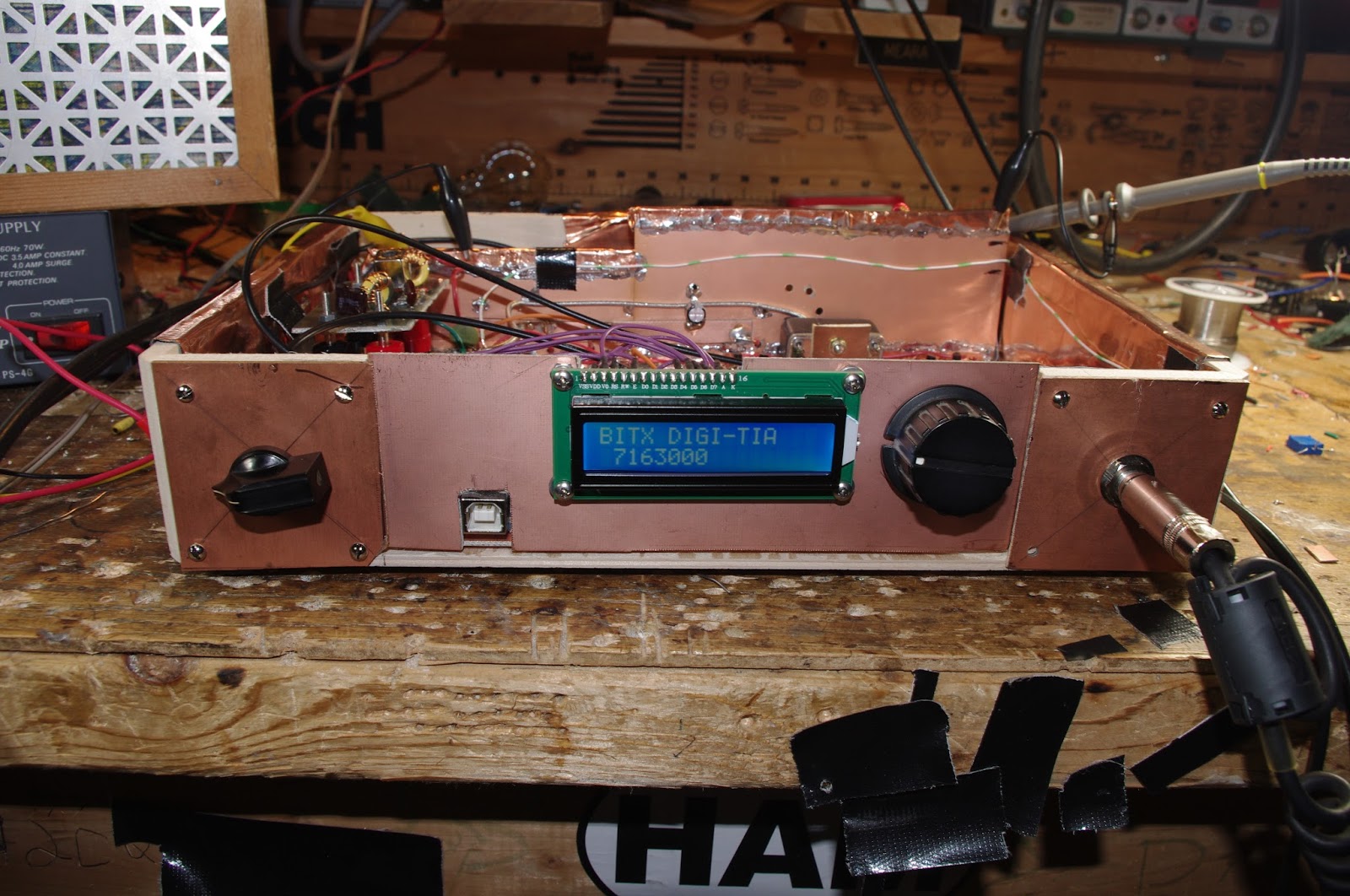
Podcasting since 2005! Listen to Latest SolderSmoke

Showing posts with label BITX DIGI-TIA. Show all posts

Thursday, October 22, 2015

November 2015 QST -- Wrist Radios, Phase Noise, and a 1958 BITX!


A Early BITX


I liked this issue.  Highlights:

Page 30.  Glen Popiel's article on the Arduino.

Page 33.  I know this may come as a surprise, but in spite of my admitted Ludite tendencies, I found the article on High-Speed Wireless Networking to be very intriguing.   

Page 38.  Hey!  Mike Aiello N2HTT has an article about an Arduino-based CW recorder.  FB Mike!

Page 54.  Review of LNR LD-5 QRP Transceiver. "The LD-5 is actually an SDR in a box with switches and knobs..."  They give a phase noise graph.

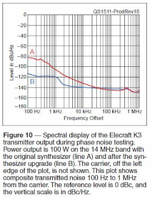
Page 58.  Review of Synthesizer upgrade for the Elecraft K3.  Uh-oh.  Phase noise again.  The review says the upgrade results in a reduction of phase noise, but the graphs seem to show an increase in transmitted phase noise on 20 meters as soon as you go 10 kHz from the transmit frequency.  I guess this is a tradeoff for a larger decrease in close-in (less than 1 kHz spacing) phase noise?  But if the objective on the transmit side is to deal with "a major problem with multiple operators in the same band segment in close proximity" resulting from transmitted phase noise,  is this a good trade-off?   Also, it would  have been interesting to know if the reviewer could detect -- by ear -- any improvement in the received signal.  

Wayne Burdick, N6KR, of Elecraft e-mailed us to let us know that there was an error in this QST article.  The original graph in the article showed an improvement in phase noise at close-in frequencies, but it also showed a significant worsening of the phase noise beyond 10 kHz.  THIS CHART WAS INCORRECT.    The Upgrade does, in fact, improve the phase noise performance.  A corrected version of the article appears here:
 
Here is the corrected graph:


Page 71.  My nightmare.  The WristRig.  The Apple Watch on 40 meters.  Sorry Steve, Dick Tracey did not have The Knack, and tackling the "Apple Watch challenge" is not an indication of "homebrew chops."  Software coding chops yes, but homebrewing is, for me, a different thing.   (But, as we always say, too each his own... And thanks to Steve for the interesting article. )

Page 82.  Ross Hull.  Very interesting article, especially the part about OM Ross's untimely death by electrocution.

Page 100.  "The Cosmophones" by Joe Veras.  Cool pictures (as always) from Joe.  And I loved the first lines:  "What in the world is a bilateral transceiver?  Byron Goodman, W1DX, posed that question in his June 1958 QST review of  the Cosmophone 35."    Wow, four months before my birth By Goodman was writing about BITXs in QST!

Sunday, October 18, 2015

HB2HB! N3FJZ-N2CQR Si5351 and BITX TIAs on Both Sides, with Some LBS and Peter Parker Circuitry Too!


In those dark days of February 2015, when all the members of the SDR ESSB Panoramic Spectral Police were on my case over some imperfections in my 40 meter homebrew SSB signal, Rick, N3FJZ came to my rescue by sending me a great YouTube video of his reception of my new rig.  Rick was using a wonderful homebrew Direct Conversion receiver with a really cool PTO.   Here is my blog post on Rick and his receiver:

Then, yesterday, I received this e-mail:


Bill, Pete,

I want to share my excitement with you.

After 32 years as a ham, I finally had my first ever HF QSO on October
16, 2015, and on a homebrew rig no less!  Oh the Joy of Emission!
It was on 7.242MHz, 8:00 a.m. eastern on the "Woodpecker net".
- Rig was based on the Bitx, using ZIA bidirectional amps.
- 20 Watts into a 80 meter full-wave loop up at 20 feet.
- 600 ohm homebrew open wire ladder line.
- Balanced antenna coupler inspired by the Annecke and Johnson matchbox
units.
- and most importantly, the Arduino controller software and use of the
Nokia display were derived and inspired from Pete's "Let's Build
Something" code presented on his website, and the carrier
oscillator(BFO) & L.O. are generated by an Adafruit SI5351 clock
generator board.  Thank you Pete.

See my N3FJZ look-up on QRZ.com for photos of my homebrew rig. I have
also put links to the SolderSmoke blog and to Pete's web page and blog.

I just want to tell you both that your podcasts, websites, circuit
diagrams and stories were a huge part of my success.  They were the
inspiration I needed on many dark days when my amplifiers would
oscillate, and my oscillators would simply smoke.  At times I thought I
would never get on the air, but an hour listening to SolderSmoke podcast
would give me the drive venture on.  Thank you!

***VERY IMPORTANT!!!!

Bill, during my first QSO, I was getting 5x8 and 5x9 signal reports
(with 20 watts!)from North Carolina, up-state New York, Michigan, and
Indiana, and I know we are only about 50 miles apart (I'm in north
central Maryland), so I believe we could probably achieve a successful
HB2HB contact if you want to try.

If you want to, and have the time, you could join me on the Woodpecker
net any Friday, Saturday or Sunday on 40 meters 7.242MHz 8:00 a.m.
eastern, or we could set-up a prearranged contact on a General class 40
meter frequency of your choosing.  Let me know - making an HB2HB
contact with you would mean the world to me.

Pete, I also extend this invitation to you as well, but with only 20
watts on my end, it may be a stretch, but we could try.

Thank you both again for the joy you have given me with your pod-casts.
73
Rick - N3FJZ
.................

Rick and I got together on 7.288 MHz yesterday evening.  It was a really amazing QSO.  Rick made a video of it (see above) and I recorded the audio on my side.  My old tape recorder didn't do Rick's signal justice -- it sounded better than this.  But here is the full QSO:


Be sure to listen closely at around 21 minutes when Rick describes a software feature that allows him to switch -- with the touch of a button -- from high side VFO to low side VFO.  The BFO frequency also changes to account for the resulting sideband inversion.  Very cool.

Rick's Digital Board

Ricks Rig as it was during our QSO
 
Crystal Filter

Rick's Dual HEXFET Power Amplifier
 
Check out the N3FJZ QRZ.com page for more info. 
 
CONGRATULATIONS TO RICK!  


Friday, October 16, 2015

Dean's TIA Transceiver with Si5351 (Video)


Nice work Dean!  With this rig, Dean recently had his first ever ham QSO.  FB OM.

Monday, October 12, 2015

Mikele's Croatian Zia and the N6QW Cult


I was telling Pete that thousands of years from now, archeologists will be puzzled when they find, in many remote corners of the world, strange homebrew electronic devices with the symbol "N6QW" emblazoned on them.  Who, they will ask, was the cult leader N6QW, and how did he get his followers to build these devices? 

Thanks to the work of Mikele 9A3XZ,  Croatia will surely be a major center for research into the N6QW cult.  Check out Mikele's video.  Stick around for the full 6 minutes and you will see the many N6QW rigs that Mikele has built.  FB Mikele!   Keep up the good work!

Friday, October 9, 2015

Dean's Double First: First Ham Contact Is Also His First Homebrew Contact


Hi Guys,
    I just had my first QSO with my ZIA transceiver!  Contact was with W8ERN in Brighton Michigan, which is approximately 300 miles from my QTH in Nashville Indiana.  W8ERN said I was barely audible and was surprised that he could hear me at all.  Especially when he found out that I was running less than 5W on an end-fed wire.  From what I heard, band conditions were pretty poor due to a magnetic storm.
    Sorry I didn't get any video of the QSO.  I heard him calling CQ and just answered.  I didn't expect him to return my call.  Btw, this was my first QSO as an amateur.  I was a bit nervous, I don't know why.  I plan on installing a 40M dipole before winter sets in so, hopefully my signal will get out a little further. 
    I have one other question.  I am considering purchasing a used rig in the next few months.  What would either one of you recommend?  I am not abandoning my home-brewing but it would be nice to have a back up rig when conditions are bad.  My budget is around $200 or so, and I don't mind something that might need some repairs.  There is a hamfest in Fort Wayne(my hometown) next month, so I might go up there and do some shopping.
    Thanks again for all of your encouragement and knowledge.   
 
73's
Dean AC9JQ
------------------------------
 
Hi Dean,
 
Congratulations on your first contact on the TIA AND your 1st contact as a ham. Bravo. Time to have a real celebration. Get cracking on that antenna before you have snow on the ground!!!
 
W8ERN, Angelo is an outstanding amateur and and a real gentleman. He has a very interesting past life. I think he worked for Multi Elmac and Central Electronics. During the 1940’s to 1960’s these companies produced some of the best ham gear. The AF-67 Transciter and the PMR8 were used mobile and of course the CE 100V and 200V were the first No Tune vacuum tube transmitters. So you were talking to one of the radio gods.
 
Again Congratulations Dean --- Bravo.
 
73’s
Pete
 
--------------------------
 
Dean:
 
Wow that's great.  Indeed the band conditions are about as bad as they get.  So bad that they are seeing Northern Lights (Aurora) far south into the USA.  Give it a few days and you will find much better conditions.
 
My advice on a commercial rig: DON'T!  You may think that they'd do better when conditions are poor, but they really won't.  If you want a bit more power, build an amp for the TIA. 

You are off to such an amazing start as a true homebrew ham.  Stay on the homebrew path.  Build a completely homebrew station!  Congrats! 

73  Bill

Monday, September 7, 2015

Si5351 and the Spectral Purity Mask


I was thinking about spectral purity standards and the Si5351 chip. I realized that I didn't even know what the FCC standards for "close in" noise are.   The standards for spurious emissions ARE well known, but these are for harmonics and parasitic emissions relatively far from the desired signal.  What about unwanted signals CLOSE to the desired signal? 

My old 2002 ARRL handbook indicates that the FCC has not established firm standards for this "close in" noise.  (They call it "out of band" noise, but are clearly referring to noise that is close to the desired signal but spreading out beyond the desired bandwidth.  Phase noise would be in their category.)

In the course of my Googling, I found the above spectral purity mask.   I don't know where it comes from, but I think it is the kind of graph that would be very useful to us as we evaluate the merits and shortcomings of various frequency synthesizers.  Would our DDS or PLL rigs fit in this mask?   I think an Si5351 rig WOULD.  According to KE5FX's measurements, at a mere 100 Hz from the center frequency, the Si5351 phase noise is already -90 db.

Does anyone have a similar mask showing current standards?

I still don't understand why so many folks believe that the Si570 is a useful part for homebrew rigs, but the Si5351 is not.  Look at the numbers:

Si570
Clifton Labs  measuring at 30 MHz carrier. At 10kHz from carrier:   -109.6 dbc/Hz
Silicon Labs web site (carrier freq not specified) At 10 kHz from carrier:  -116 dbc/Hz

Si5351
KE5FX measuring at 19.99 MHz. At 10kHz from carrier:  -127 dbc/Hz
Silicon Labs  measuring at 156.2 MHz. At 10 kHz from carrier   -112 dbc/Hz.

Can anyone out there explain the technical basis for the belief that the Si570 is a useful part while the Si5351 is not?   

It is important to keep things in perspective.  ALL of these noise numbers represent VERY small noise levels.   Let's keep is simple and assume a 100 watt carrier signal and a phase noise of -100 dbc/Hz.   That means the phase noise per hertz would be .00000001 watts.  That's watts/hertz.  How much "noise power" would that represent in a typical SSB passband?  Multiply by 2500 Hz and you get 25 microwatts.  That's really low noise levels. Not enough to worry about.  And as we've noted, we've happily used rigs with LC VFOs and crystal oscillators for all these years without every once measuring their phase noise.

Our book: "SolderSmoke -- Global Adventures in Wireless Electronics" http://soldersmoke.com/book.htm Our coffee mugs, T-Shirts, bumper stickers: http://www.cafepress.com/SolderSmoke Our Book Store: http://astore.amazon.com/contracross-20

Saturday, September 5, 2015

Alan Wolke's Drake 2-B (video)


Alan's video inspired me to do a little work with my Drake 2-B.  Nothing major -- I was just making sure that the passband knob is in the right setting.  I've complained that the Drake 2-B doesn't sound great on AM.  I recently noticed that my BITX40 DIGI-TIA sounds surprisingly good with AM signals -- I just treat them as SSB signals and zero-beat the carrier with my Si5351 VFO.  I wanted to try doing the same thing with the 2-B, and then make some comparisons.  I only heard a few AM signals this morning, so I will try again later today and will report results here.   

Our book: "SolderSmoke -- Global Adventures in Wireless Electronics" http://soldersmoke.com/book.htm Our coffee mugs, T-Shirts, bumper stickers: http://www.cafepress.com/SolderSmoke Our Book Store: http://astore.amazon.com/contracross-20

Tuesday, August 18, 2015

Another BITX DIGI-TIA -- AC9JQ's (video)


Wow, Dean's BITX with Termination Insensitive Amplifiers (3 of them) sounds really nice. And this is with a homebrew ladder filter (see below).

 
I also like the way Dean makes his enclosures -- he uses scrap aluminum and 1/2" angle.  This might cause me to abandon the wooden cigar boxes.


Dean will now add the driver and PA stages and plans on following Pete's suggestion by making this a 20/40 rig. 

Our book: "SolderSmoke -- Global Adventures in Wireless Electronics" http://soldersmoke.com/book.htm Our coffee mugs, T-Shirts, bumper stickers: http://www.cafepress.com/SolderSmoke Our Book Store: http://astore.amazon.com/contracross-20

Thursday, July 16, 2015

Dean's Tiny Tia -- Hardcore Homebrewing


Hi guys,

I've been on kind of a building hiatus due to various issues, but after seeing the work being done with the termination insensitive amplifiers I had to start noodling again.....as Pete would say.  Well I have decided to build a TIA (ZIA according to Pete) SSB transceiver.  I've decided to homebrew everything including the DBM, crystal filter, and even the Si5351 module.  As I wait for more parts to come in, I wanted to show the 2 TIA amps and crystal filter assembly I've built.  I've included a screenshot of the pass band response through the amps and the crystal filter.  It looks the same in both directions and everything fits into an area of 2 x 2.5 inches.  With the space left on the board, I hope to be able to put my SBL-1 clones on as well.  I follow up as I get more completed.

73

Dean AC9JQ


Our book: "SolderSmoke -- Global Adventures in Wireless Electronics" http://soldersmoke.com/book.htm Our coffee mugs, T-Shirts, bumper stickers: http://www.cafepress.com/SolderSmoke Our Book Store: http://astore.amazon.com/contracross-20

Sunday, June 28, 2015

New Rigs but Old Mics


So now I have THREE BITX transceivers on the operating bench.  I've been getting tired of moving the old D-104 around as I change bands.  Surely each of these rigs merits its own mic.  This would allow me to avoid the hassle of having to adjust the level on the D-104 each time I change rigs.

Fortunately in the junk box I have some useable old mics.   An old "Turner SSB+2" mic  has been kicking around in there for decades.  I probably got it when I was a kid. The element was no longer working, so I just popped an electret element in there, took out the preamp circuit, but kept the adjustment pot.  At first I had a 3.3 uF coupling cap in there at the output, but this was letting too much 300 Hz energy through.   So I changed the coupling cap to .1 uF and this seemed to even things out a bit. 

I know, I know: It is CB gear.  It is painted BLUE and it looks like something George Jetson would use to talk to his interstellar Good Buddies. But it was preceded by a very similar mic made for hams (see above).   And I like it.  It even has the word "Transistorized" emblazoned in script across the PTT bar. 


Our book: "SolderSmoke -- Global Adventures in Wireless Electronics" http://soldersmoke.com/book.htm Our coffee mugs, T-Shirts, bumper stickers: http://www.cafepress.com/SolderSmoke Our Book Store: http://astore.amazon.com/contracross-20

Tuesday, June 23, 2015

Video of Pete's VERY COOL Zia Build


This is cool in so many ways:

I like the RF amp along the back with the LP filter off to the side.

The stacked PC boards are very nice.

The Display -- What can I say?

Having stations from the Philippines (DU) for the receiver demo.  Nice touch.

Mesh-like side panels!  And the plexiglass top!  Wow!

PAINTING THE COPPER-CLAD FRONT PANEL BLACK!  WOW!  BLACK IS THE NEW COPPER!

Nice feet for the rig.  Feet are key.

NO NOTICEABLE PHASE NOISE.  No Si5351 output bleed-over.

Love the name:  ZIA!!  (That was my only contribution.)

Monday, June 22, 2015

Pete Puts His Zia in a Box

 
Wow, Pete really knows how to pack a lot electronics into a small box.  (He claims that he does this to justify the $250000 CNC machine!) I remain very jealous of that cool display panel. 


Our book: "SolderSmoke -- Global Adventures in Wireless Electronics" http://soldersmoke.com/book.htm Our coffee mugs, T-Shirts, bumper stickers: http://www.cafepress.com/SolderSmoke Our Book Store: http://astore.amazon.com/contracross-20

Thursday, June 18, 2015

Progress on Pete's "ZIA"


It is practically SPARKLING!   Beautiful job Pete.  I'm glad you are actually boxing this one up! 

Pete has many more pictures of this project here: 
http://www.n6qw.com/TIA.html

He also notes that there may have been some sub-conscious Knack wisdom at work when I dubbed his rig "The Zia."   I was thinking strictly in terms of language and ethnic heritage:  TIA stands for Termination Insensitive Amplifier.  But in Spanish it means "aunt".  But in Italian Aunt comes out as Zia.  So Pete's should be a Zia, right?  Capisce?

Well Pete puts an electronic twist on it:

"Once again you are spot on with ZIA (With  Z the electronic symbol for Impedance).  Thus Impedance (The symbol Z) Insensitive Amp. Thank You."

 Our book: "SolderSmoke -- Global Adventures in Wireless Electronics" http://soldersmoke.com/book.htm Our coffee mugs, T-Shirts, bumper stickers: http://www.cafepress.com/SolderSmoke Our Book Store: http://astore.amazon.com/contracross-20

Saturday, June 13, 2015

SolderSmoke Podcast 177 Bicoastal Termination Insensitivity Unphased by Phase Noise

 
SolderSmoke Podcast #177 is available:
 
 
13 June 2015
 
-- PETE JULIANO INDUCTED INTO THE QRP HALL OF FAME
-- Bench Reports:  Bicoastal Bilateral Success:  A Tale of Two Tias
    Only 3 TIA rigs in the world?  It depends...
    Relay improvements in the BITX Builds
    Straightening out amp problems
    The many uses of copper foil
    No phase noise or bleed-over troubles
    Plug-in filters
    Adjusting TIA amp gain on RX and TX (too much is not good!)
    Getting the BITX to work with the CCI amp
    Allison wisely prescribes 3 db pads 
    Curing hum by moving the power supply (duh!)
-- Farhan's New Minima -- Crying out for an Si5351?
-- Mike KL7R's Web Site is Back (thanks to W8NSA)
-- SolderLex: Rigs or Radios?  We go with Rigs
-- A ham rite of passage:  Build a Dipole!
-- What does your shack look like at the end of a project?
-- MAILBAG 
    The CORRECT pronunciation of Belthorn
    Multiplication and Division by 4
    W8NSA, Vietnam, a Transoceanic and a 9V Battery 


Our book: "SolderSmoke -- Global Adventures in Wireless Electronics" http://soldersmoke.com/book.htm Our coffee mugs, T-Shirts, bumper stickers: http://www.cafepress.com/SolderSmoke Our Book Store: http://astore.amazon.com/contracross-20

Tuesday, June 9, 2015

Termination Insensitivity -- Only Three TIAs in the World?


Termination Insensitivity.  Is this like when your girlfriend dumps you and you just don't care? 

No. It's more like this:

http://www.n6qw.com/TIA.html

Wes Hayward and Bob Kopski developed the Termination Insensitive Amplifier circuit back in 2009.  With a bidirectional rig it is important that the crystal filter face the same impedance in both directions.  Simpler bidirectional amps are impedance "transparent" in that their input impedance depends on what is on the output (and vice versa).  The circuit that Wes and Bob developed solved this problem:  these amps always look like 50 ohms.  That's very useful.  When I was building my earlier BITX rigs, Farhan suggested that I try the termination insensitive amp circuits.  On my latest project I followed his suggestion.  At the same time, Pete was building a new BITX, also using the TIA amps. 

Pete wrote to Wes and Bob and asked if anyone had followed through on their 2009 article by building a rig using this circuit.  Wes said that he was unaware of any TIA rigs.  It turned out that Tom Hall up in New York City had built one (video below). So I guess Pete's rig is TIA 2 and mine is TIA 3!  (But I was thinking, because of Pete's Italian ancestry, shouldn't we call his rig a Zia?)
Please let us know if you know of any other TIAS (or ZIAS!) out there.

Here is Tom Hall's very FB TIA:


Our book: "SolderSmoke -- Global Adventures in Wireless Electronics" http://soldersmoke.com/book.htm Our coffee mugs, T-Shirts, bumper stickers: http://www.cafepress.com/SolderSmoke Our Book Store: http://astore.amazon.com/contracross-20

Friday, June 5, 2015

BITX DIGI-TIA Build Update #7: On The Air!

 
With lots of encouragement from Pete, I finally got the BITX DIGI-TIA on the air.  The first contacts were made yesterday. I have it on 40 meter SSB.  The finicky denizens of that audio-conscious band seemed to like the sound of the rig.   I was almost reluctant to tell them it is homebrew (no need to stir up trouble!)
 
The plug in filter arrangement seems to work very well.  This will allow me to put this rig on many other bands.  All I have to do is build some additional filter boards and upload modified versions of the software.  There is even space to make a plug-on socket for the crystal filter (the 9 MHz IF would not be cool for 17 meters).  
 
I'm really pleased with the RF power chain (the original BITX chain).  This time I built it all in a straight line along the back of the transceiver with lots of attention to shielding and grounding.  There were no instability problems.  The amplifiers did not try to be oscillators.  I was shocked!
 
I did have to reduce the gain of the three termination insensitive transmit amplifiers. Using the chart in the 2009 Wes Hayward/Bob Kopski article,  with just a few resistors you can set the gain.   I had built them with 19.4 db gain each.  This turned out to be too much -- the slightest amount of audio into the SBL-1 was driving the amplifiers to peak output.  So yesterday I changed all three amps to 15 db (I think that was what Farhan had in the original BITX).  It only took me about 15 minutes and it seemed to take care of the problem.  I am getting 7 or 8 watts out of the IRF-510.
 
T/R switching is very smooth and quiet using just two small 12V relays.
 
Thanks to Pete for the mil-pad boards and the encouragement (especially on the use of the Si5351).  Thanks to Farhan for the BITX architecture. Thanks to Steve Smith for the Yaesu filter.  Thanks to Wes and Bob for the TIA circuit.  Thanks to Thomas in Norway for the Si5351 software.  And Thanks to Allison for all the good advice.


Our book: "SolderSmoke -- Global Adventures in Wireless Electronics" http://soldersmoke.com/book.htm Our coffee mugs, T-Shirts, bumper stickers: http://www.cafepress.com/SolderSmoke Our Book Store: http://astore.amazon.com/contracross-20

Saturday, May 30, 2015

BITX DIGI-TIA Build Update #6: Boxing it up!

 
Basic Basswood Box (From Michael's or Amazon)

 
Space cut out for Si5351 board and for AF Gain and Mic jack

 
Copper flashing placed (from Home Depot)

 
Amplifier Chain placed along the back
 
 
Note Plug-In Low Pass Filter

 
Starting to look Rig-ish

 
The View from Above

 
Still to do:
 
Socketry along the back (Antenna, 12V, external amp T/R control, Speaker, MAYBE:  IF connection).
 
 
Relay wiring (I'm trying to do this with just 2 DPDT relays: one for Low Pass Filter switching and External Amp T/R control,  and one for 12V T/R switching, and Bandpass Filter switching.
 

Our book: "SolderSmoke -- Global Adventures in Wireless Electronics" http://soldersmoke.com/book.htm Our coffee mugs, T-Shirts, bumper stickers: http://www.cafepress.com/SolderSmoke Our Book Store: http://astore.amazon.com/contracross-20

Wednesday, May 27, 2015

BITX DIGI-TIA Update #5: Amplifiers Built and Tested


I have the RF amplifier stages done, and I worked a bit on the shielding.  This circuit board will be along the back, turned around, with the copper-clad shields between the amps and the rest of the rig.  In the picture you can see the small inter-stage shields, and one that put between input and output on the final.  All this in the probably vain hope of avoiding the Agony of Oscillation.   We'll see.  So far so good.  I get about 8 watts out of the IRF510 on 40 meters.  53db total gain for the three stages.  Of course, all this will likely change once the rest of the rig, the LP filter and an actual antenna are added.
 
As for the mic amp problems I mentioned last time, well,  I discovered on earlier BITX projects that one of the resistors in the base circuit needs to be changed from 10K to 39K.  It is kind of a long story (maybe for the podcast) but essentially I had to discover this AGAIN.  More details here:
 

Our book: "SolderSmoke -- Global Adventures in Wireless Electronics" http://soldersmoke.com/book.htm Our coffee mugs, T-Shirts, bumper stickers: http://www.cafepress.com/SolderSmoke Our Book Store: http://astore.amazon.com/contracross-20

Tuesday, May 26, 2015

BITX DIGI-TIA Update #4


Lots of progress over the long weekend.  Along the back you can see the three stages of the RF amplifier chain:  2N3904, 2N2218A, IRF510. I intend to add inter-stage shielding, and one long shield between the chain and the rest of the rig.   Front and center is the Si5351 board (code by LA3PNA).  Mic amp (which gave me a lot of trouble!) is to the right of the Si5351.   AF (RX) amp is to the left (2N3904 and LM386).  The big board in the center has the three Termination Insensitive Amplifiers (thanks Wes and Bob), the 9 MHz filter (thanks Steve Smith!) and the two SBL-1 mixers (thanks to Pete Juliano for the "mil-pad " boards).  And thanks to Farhan for the overall BITX concept and the TIA suggestion.  
 
In the upper right you will see where the plug-in low-pass filter will plug in (a better picture appears below).   I will use a similar plug-in for the band-pass filter.   Combined with the BFO/VFO flexibility of the Si5351, this plug in feature should allow me to cover many bands with this rig.    


Our book: "SolderSmoke -- Global Adventures in Wireless Electronics" http://soldersmoke.com/book.htm Our coffee mugs, T-Shirts, bumper stickers: http://www.cafepress.com/SolderSmoke Our Book Store: http://astore.amazon.com/contracross-20

Monday, May 18, 2015

BITX DIGI-TIA Build Update #3 Video of Receiver in Operation


A few things I forgot to mention in the video:

That USB port on the front panel has already come in handy.  I needed to switch the tuning increment from 1 kHz to 100 Hz.   I just went into the Arduino program, removed one zero, and then re-uploaded the code.  

I also put to use the sideband inversion rule-of-thumb:  My IF is at 9 MHz.  I want to receive signals in the 7.2 MHz range, and I want the VFO running ABOVE the IF frequency.  So obviously the VFO will be running at around 16.2 MHz.  So, rule-of-thumb time:  Will I be subtracting the frequency with modulation from the frequency without modulation?  Yes I will!  So, there will be sideband inversion.  This tells me where to position my BFO frequency.   The signals on 40 start out as Lower Sideband.  But as explained above, by the time they get to the filter they will be inverted and will be upper sideband signals.  So I need to put the BFO slightly BELOW the filter passband so that I can tune the signals in such a way as the sidebands fit into the filter passband and have the proper frequency relationship to the BFO to allow for demodulation. I put it at 8.9986 MHz.  With the Si5351, changes to the BFO and VFO frequencies are very easy.

Our book: "SolderSmoke -- Global Adventures in Wireless Electronics" http://soldersmoke.com/book.htm Our coffee mugs, T-Shirts, bumper stickers: http://www.cafepress.com/SolderSmoke Our Book Store: http://astore.amazon.com/contracross-20
Designer: Douglas Bowman | Dimodifikasi oleh Abdul Munir Original Posting Rounders 3 Column