Podcasting since 2005! Listen to Latest SolderSmoke

Showing posts with label UK. Show all posts

Thursday, March 4, 2021

"The Secret Life of..." Tribal Knowledge!


It is great to hear that Tim Hunkins is producing this new series.  It looks like it will be largely about "know-how" -- about what we'd call "tribal knowledge." 

Saturday, February 27, 2021

Update from the Wizard of Wimbledon -- "Always listen to Pete"

In a recent podcast, Pete mentioned that Leo Sampson (the young Brit who is rebuilding the sailing yacht "Tally Ho") should seal the deal with his girlfriend.   Well, it seems that "life coach" should be added to Pete's already impressive list of abilities (homebrew hero, pasta chef, guitar player, etc.)  A while back Pete gave similar advice to Jonathan, M0JGH.   This morning, Jonathan reported in, confirming that Pete's advice was completely correct.  A "mixing product" arrived early in the lockdown. Congratulations to Jonathan and his remarkably radio-tolerant wife.  It seems Leo should be shopping for a ring. 

--------------------------  

Dear Bill and Pete

I hope that you and your families are staying very well during these extraordinary times.

I wanted to thank you both for the reminiscent shout-out during the last podcast, whilst you were suggesting that Leo Sampson of sailing yacht Tally Ho should "seal the deal" with his girlfriend. If our case study is indicative of his future prospects, he absolutely should do! Not only are we happily married but we welcomed a bubbly baby girl into our family at the start of lockdown. (I note that hams refer to children as “harmonics”, but wouldn’t mixer products be a more appropriate metaphor?) 

Apologies for my radio silence of late. Circumstances have allowed me the rare and special opportunity to take more of a lead with parenting, and so my soldering iron has only been wielded for maintenance purposes rather. Your discussion about the intrigue of distant voices emerging from homebrew rigs has whetted this CW addict's appetite to build something for SSB or even DSB, and likely for one of the higher bands...

I feel that I should briefly stick up for the art of CW, though. As a keen amateur musician the ability to communicate through rhythm will always hold a special charm, particularly when you consider that many of my regular EU chums on 40 and 80 are easily identifiable by their “distinctive fists”. I recall a true WW2 spy story in which a double agent, I forget which, was rather unwell but still had to be carried into the radio tent to send his CW whilst lying on a stretcher, otherwise the Germans might notice the absence of this distinctive fist and realize that the game is up!

73 from Wimbledon

Jonathan
M0JGH

Sunday, January 31, 2021

Repairing My Maplin Audio Waveform Generator

I picked this generator at the Kempton Park rally in London many years ago.  I use it quite a bit, not only for circuit testing but also as an easy way to get my homebrew BITX rigs to send a signal so that I can adjust my antenna.  I just plug this thing into the mic jack, crank in a small amount of 1 kHz audio, and I am ready to minimize SWR. 

It never gave me any real problems until last week.  I opened it up and examined the circuitry for the first time.  Lots of mystery chips in there. Fortunately they are all socketed.  Thank you Maplin. 

Even without really knowing how each of the ICs work, it was easy to troubleshoot. See the schematic in the article that begins on page 21 in this .pdf: 

My Rigol scope showed a good signal going into and coming out of IC8, the LF351 op-amp.  From there the signal goes to IC5 a 4066BE.  But nothing was coming out of IC5.  Thus IC5 was my lead suspect.  I put in a quick order to Digikey.  A couple of days and a few bucks later the chips (as always, I ordered several) were on my doorstep.  Within a few minutes IC5 was replaced and the generator was as good as new. 

One annoying problem with this generator is that it has no automatic shut-off circuitry.  So if I forget to turn it off, I soon have to buy two 9V batteries. Tony G4WIF suggested a simple timer circuit.  I may do that soon.  Or, given that we are already on the IC dark side with this project, there is this: https://www.youtube.com/watch?v=C4C2H_3BU3o&feature=youtu.be 

I recently find myself replacing a lot of chips in various rigs and devices in my shack.  It seems that chips go bad more frequently than discrete transistors or even tubes.  But maybe I'm just using older gear with older, more fragile chips.   What do you folks think? 

Friday, January 22, 2021

Jenny List's Favo(u)rite Things

Over on Hack-A-Day Jenny List (G7CKF)  has a really nice article about ham radio and homebrewing.  She truly has The Knack:  She got her start in radio electronics at age 9 when her parents gave her George Dobbs's Ladybird book.   

https://hackaday.com/2021/01/21/a-few-of-my-favorite-things-amateur-radio/

One of her paragraphs really seemed to capture the SDR-HDR conflict that we so often joke about: 

The age of the homebrew RF tinkerer may be at a close, at least in the manner in which I started it. Nobody at the cutting edge of radio is likely to be messing around with discrete transistor circuits in the 2020s, unless perhaps they are working with extremely exotic devices up in the millimetre wavelengths. It’s all software-defined radios, opaque black plastic boxes that deliver a useful radio experience on a computer but that’s it. No more homebrew, no more tinkering. 

Whew, good thing I'm not on the cutting edge.  It sounds kind of sad.  Oh well, that leaves more discrete transistors for us to tinker with.  

Jenny's Profile on Hack-A-Day: 

[Jenny List]: Contributing Editor and European Correspondent

Jenny List trained as an electronic engineer but spent twenty years in the publishing industry working on everything from computer games to
dictionaries before breaking out and returning to her roots.

She grew up around her parents’ small farm and blacksmith business in rural England, so making (and breaking) things is in her blood. Countless projects have crossed her bench over the years, though these days you’ll find her working with electronics and in particular radio, textiles for clothing and costume, decrepit classic cars, and real cider from first principles.

When she’s not writing for Hackaday she works on language corpus analysis software, designs and sells amateur radio kits, sits on the board of Oxford Hackspace, and is a freelance electronic design engineer and programmer.

Thanks Jenny! 

Thursday, January 21, 2021

Saturday, January 16, 2021

Nick M0NTV's Really Useful SDR Transceiver (video)


Even though I am more of an HDR guy, I really liked Nick's SDR rig.  I like the modular approach, with all the modules inside a transparent plastic box (see below).  Don't worry about the shielding Nick -- I had the same concern about my BITXs in wooden boxes, but they worked fine. 

Nick really did a great job on the video.  The bloc diagram was especially useful, both on the hardware and on the software.  Very cool.   It is nice to use this phasing approach,  with the digital magic happening at audio frequencies.   I fear that soon FPGAs and direct digital sampling will take the hardware fun out of these rigs.  We already have a bit of that with the RTL-SDR dongles. 

Very cool how the Teensy takes care of the 90 degree audio shift.   I had to do that with chips in my phasing receiver. When I first saw Nick's bloc diagram, I was looking for the audio phase shift network -- then he explained that that was in software, in the Teensy. 

Nicks arrangement for switching the filters is very nice.  

Thanks Nick!  


Wednesday, January 13, 2021

Tuesday, January 12, 2021

Pete N6QW and Steve G0FUW Talk to RSGB About Homebrew (Video)


Wow, what an unexpected treat!  Here we can watch Pete N6QW and Steve G0FUW talk to the Radio Society of Great Britain about homebrew radio.  Steve talks about kits and scratch-built rigs.  I really liked seeing his early rigs and his description of how building these rigs helped him become a more advanced homebrewer.  I also liked his mention of George Dobbs as a guiding light in the QRP and homebrew world. 

Pete focuses on SDR and provides a really great description of this approach to homebrew.  I was struck with how great it is that, after a lifetime of HDR building, Pete is willing to embrace this new technology. He talks about it as part of "a learning journey."  As always, he sets the example for us all.   

Thanks to Pete, Steve, and RSGB. 

Saturday, December 5, 2020

"Radio, Radio" By Elvis Costello and The Attractions


Wow. At one point in the video Elvis C. climbs onto a radio chassis and sings while standing between two Thermatrons.  FB OM.  

And here is an interesting article about Elvis Costello's music, and opposition to Fascism. 

Thursday, November 19, 2020

Diode Ring Magic


I continue to work on the product detector of my Lafayette HA-600A.   This work has caused me to brush up on my understanding of how mixers really work.   

I think one of the most interesting mixer circuits is the diode ring.  With just four diodes and one or two transformers, this device manages to take an incoming signal and multiply it by either 1 or -1 depending on the polarity of the local oscillator signal.  That is pretty amazing.  

Alan Wolke W2AEW did an excellent video on this: https://www.youtube.com/watch?v=junuEwmQVQ8

Inspired by Alan, I took my most recent homebrew diode ring mixer (with transformers from Farhan, diodes from Jim W8NSA, and a PC board base from the CNC mill of Pete N6QW) and hooked it up to two signal generators and an oscilloscope.   I had the local oscillator at 10 MHz and the signal oscillator at 7 MHz.   You can see my results in the pictures (above and at the end).  You can see the resulting difference frequency (3 MHz) in the broad up and down pattern.  And you can see the sum frequency (17 MHz) signal in the faster oscillations.  All you would need is some filtering to separate them out.  


I really like the RSGB Handbook diagram (above).  I think the bottom schematic with its crossed diodes really explains how the phase reversal takes place:  when the LO turns on D1 and D3 (the horizontal ones), multiplication by 1 takes place.  But when the LO turns on D2 and D4 (the crossed  diodes), up goes to down and down to up, creating phase reversal, or, in math terms, multiplication by -1.  

At a more basic level, mixing takes place whenever -- in a non-linear circuit -- one signal is controlling the gain or attenuation experienced by the other signal. A complex waveform results, a waveform that contains sum and difference products.  A circuit like the diode ring, that alternately multiplies by 1 and -1, is non-linear in the extreme, and the multiplication is controlled by the LO.  The results can be seen in the diagram's complex waveforms, on Alan's Tek 'scope, and on my Rigol.  And in those complex waveforms you can SEE the sum and difference frequencies. That is really cool. 
 

Friday, November 13, 2020

How Does My Singly Balanced, Two-Diode, Single Transformer Product Detector Really Work?


As young James Clerk Maxwell used to say, "What's the go of it?"  and "What's the particular go of it?"

I studied this circuit carefully when I was using it as a balanced modulator in my DSB rigs.  I wrote up my conclusions in my book "SolderSmoke -- Global Adventures in Wireless Electronics." 

BALANCED MODULATOR CONFIGURATION: 

When I was using it as a balanced modulator, I had the RF "carrier" signal going into L1. This RF signal was 7 dbm, enough to switch the diodes on at voltage peaks.  With the "center tap" of L2/L3 grounded for RF, this meant that when the "top" of L2 is negative, the "bottom"  of L3 is positive.  In this situation BOTH D1 and D2 will turn on and conduct. 

When the top of L2 is positive, the bottom of L3 is negative and neither of the diodes is on.  Neither conducts. 

So we have the RF signal turning the diodes on and off at the frequency of the RF signal.  

Audio from the microphone and mic amplifier is sent into the center tap connecting L2 and L3.  The level of this audio is kept low, below the point where is could turn on the diodes.  The center tap IS grounded for RF by the .1uF capacitor, but it is NOT grounded for AF.  That is key to understanding this circuit. 

In essence by turning the two diodes on and off at the rate of the RF signal, the audio signal is facing severe non-linearity through the diodes.  We could say it is alternately being multiplied by 1 and 0.  This non-linearity is what is required for mixing.  We therefor get sum and difference products:  Sidebands.  At this point, Double Sideband.  

The way the transformer is set up means the RF carrier signal is balanced out:  Even when the two diodes conduct, the top of R1 and the bottom of R2 are of equal and opposite polarity, so there is no carrier signal at the junction of R1 and R2 (they are actually a 100 ohm variable resistor that can be adjusted to make SURE they balance out).  So the carrier is suppressed and all that remains are the sidebands:  Suppressed Carrier Double Sideband. 

PRODUCT DETECTOR CONFIGURATION:

What happens when we use this circuit as a product detector in a receiver? Let's assume we are working with a 455 kc IF.   If you run a 454 kc 7 dbm BFO signal into L1, it will turn the diodes on and off as described above.  But you will NOT be able to put the 455 kc IF signal into the center tap of L2/L3 -- that center tap is GROUNDED for 455 kc.   So you will have to run your IF signal into the resistors, and take the audio output from the center tap of L2/L3.   This works.   I tried it in my HA-600A.  But there is a problem: Envelope detection.  

In this arrangement, we are balancing out NOT the 455 kc IF signal, but instead we are balancing out the BFO.  We don't really NEED to balance out the BFO -- it can easily be knocked down in the audio amplifiers, and IT is not responsible for the problematic envelope detection.  We DO need to balance out the IF signal, because if that gets through we can get simultaneous "envelope detection" and product detection.   And believe me,  that does not sound good.

So I tried putting the IF signal into L1, and the BFO signal into the resistors (as shown above).  I took the audio  from the junction of L2/L3.  This seemed work better, with envelope detection greatly reduced. 

BUT WHAT'S THE GO OF IT? 

But how is this circuit mixing in this configuration?   The strong BFO signal is still controlling the diodes, BUT, with the BFO signal coming in through the resistors,  when the top of R1 is positive the bottom of R2 is ALSO positive.  In this situation D1 will conduct but D2 will not.  The IF signal is facing a big non-linearity. This will result in sum and difference frequencies.  The difference frequency will be audio.  But with D1 and D2 turning on and off in a very different way than we saw in the balanced modulator, how does the mixing happen?  

I think the answer comes from the summer 1999 issue of SPRAT, the amazing journal of the G-QRP club.  Leon Williams, VK2DOB wrote an article entitled "CMOS Mixer Experiments."  

Here is Leon's 74HC4066 circuit: 


I think those two gates (3,4,5 and 1,2, 13) are the functional equivalent equivalent of the two diodes in our product detector. In Leon's scheme the VFO is supplying signals of opposite polarity.  Ours is providing only one signal, but the fact that the diodes are reversed means that they act just like the gates in Leon's circuit.  The transformer is almost identical to the one we use in the product detector. 

Let's look at the output from Leon's circuit: 


"VFO A" going high is the equivalent of the BFO going to its positive peak and D1 conducting. 
"VFO B" going high is the equivalent of the BFO signal to its negative peak and D2 conducting. 

Take a ruler, place it vertically across the waveforms and follow the progress at the output as the two signals (RF A and RF B) are alternately let through the gates (or the diodes).  You can see the complex wave form that results.  The dashed line marked Audio Output shows the difference frequency -- the audio.  That is what we sent to to the AF amplifiers. 

One concern remains:   

What happens when the 455 kc IF signal getting to L1 get so strong that IT also starts to turn the diodes on and off?   I think this will result in distortion, and we can see this in LT Spice.  

Here is the output waveform when the If signal at L1 is kept below the level that would turn on the diodes: 


Here you can see it with a much stronger IF signal:  


The output waveform becomes more of a sawtooth. 

How can I prevent this from happening?   I know AGC should help, but the AGC in this receiver doesn't seem to sufficiently knock down very strong incoming signals. 

Does my analysis of these circuits sound right? 

Thursday, September 24, 2020

Global Specialties Corporation 6000 Frequency Counter -- Anyone have a Plessey SP8630B Chip?


Continuing my effort to improve my workbench and its test gear, this week I turned to an old frequency counter that I picked up at the Kempton Park Radio Rally in London many years ago. It was not working when I got it, but long-time SolderSmoke listeners will recall the tale of woe that resulted from my having soldered a replacement IC (that Tony Fishpool G4WIF had sent me) UPSIDE down.  Tough times my friends,  tough times. 

Well,  I'm working on it again.  First I converted it from 220 to 110 power.  I had a transformer in the junk box that fit nicely, both electrically and mechanically.  In the course of doing this, I learned something about this counter that I did not know:   As long as it is plugged in, even if you turn it off, the time-base oscillator keeps running.  And get this Color Burst Liberation Army members:  The oscillator runs at 3.579545 MHz.  TRGHS.    

With sunspots scarce and with Pete pessimistic about the solar cycle, VHF and UHF now seem more interesting.  I need to have more test gear for the higher frequencies.  This counter works up to 650 MHz.  Yea! 

When I first fixed this thing, I was quite pleased to get it going with "Input A -- 5 Hz to 100 MHz."  But now I want to get "Input B -- 40 MHz to 650 MHz" working also. I used a 50 MHz signal from my newly repaired HP-8640B to trouble shoot Input B.  I think one of the divider chips is bad.  It is a Plessey SP 8630B.   Does anyone have one of these chips in their junk box?  


Monday, August 31, 2020

Global Collaboration: The uSDX -- A Multi-Mode QCX


Bill:
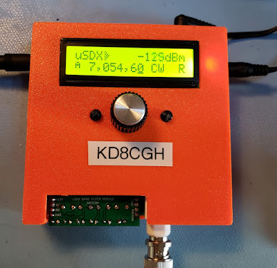
There is a new open source, home brew, multi band, multi mode QRP transceiver that grew out of the QRP Labs QCX. Through some serious magic it retains an efficient class E RF amplifier for sideband and digital modes. It crams impressive SDR capabilities into an Arduino. More info at https://groups.io/g/ucx/topics

The basic work appears to have been accomplished by Guido Ten Dolle PE1NNZ. It uses pulse width modulation of the PA supply voltage to transmit  modes other than CW while retaining class E efficiency and uses a direct conversion SDR receiver.
There are several variants by different developers. I built a variant designed by Barbaros Asuroglu WB2CBA  
https://antrak.org.tr/blog/projeler/usdx-an-arduino-based-sdr-all-mode-hf-transceiver-pcb-iteration-v1-02/ that uses through hole components (mostly) and I'm pleased with it's performance. I also designed and 3D printed a case.


This has an interesting development process with contributions by many, including the usual gang of suspects: Hans Summers, Ashhar Farhan, Manuel DL2MAN, Kees K2BCQ, Allison KB1GMX and Miguel Angelo Bartie PY2OHH. I apologize to the many others whose names I didn't list.

The band switch multiband version by DL2MAN is even smaller, but with SMD components which I wasn't ready to tackle yet.

BTW - your podcast encouraged me to go in this direction. I built a BITX 40, a uBITX (sent you a pix of it in an old Heathkit Twoer case), U3S, QCX and now my first step from kits to built from plans.

73
Bob   KD8CGH


https://antrak.org.tr/blog/projeler/usdx-an-arduino-based-sdr-all-mode-hf-transceiver-pcb-iteration-v1-02/

Sunday, August 30, 2020

Music Video -- "The Spirit of Radio" by Rush


Thanks to Thomas from The SWLing Post for putting this on his blog.

Sunday, July 26, 2020

Alan Wolke W2AEW on IMD, NanoVNA and more (presentation to UK club)


This video is another reminder of how lucky we are to have Alan Wolke W2AEW as a fellow radio amateur, and as a teacher and mentor. 

In this video, Alan is talking to the Denby Dale Amateur Radio Society in Yorkshire, UK. 

The first part of his talk is about IMD products, the importance of 3rd order products, and the benefits of attenuation. 

The second part of the talk (after a few questions) is a look at the NanoVNA, which Alan cites as the "Toy or Tool of the Year."   

I learned a lot from both portions of the presentation.  I now find myself wanting an H4 model of the NanoVNA (bigger screen).  Or maybe even an F model.   Thanks to Alan, I now know what S21 and S11 means. 

Thank you Alan, and thanks to the Denby Dale ARS.  

73  Bill 
  

Monday, June 22, 2020

Join up NOW!


From the front cover of the July 14, 1934 issue of Amateur Wireless.   This UK weekly magazine was the predecessor of Practical Wireless. 

Thursday, June 18, 2020

You must join the CONSTRUCTOR CRUSADERS


Wow. This 1934 front-page presages so many things that we talk about today. 

"The Constructor Crusaders,"  reminds me of "The Color Burst Liberation Army."

"Wear the badge and be in fashion," is clearly just another way of saying "chicks dig it," and brings to mind Pete's beret. 

Finally, "Constructor Crusaders will get the best out of radio!"  Well, that's what we've been saying all along.  

Note that as early as 1934 they were talking about TV:  "Radiovision."

Thanks to Scott KA9P for passing this to us. 

Wednesday, May 27, 2020

Antennas, Money, and Ham Psychology


During SolderSmoke Podcast #222, Pete lamented the fact that many hams are willing to spend significant amounts of money on "manufactured" dipole antennas that are little more than pieces of wire.  Tony Fishpool G4WIF sent a graphic on the wire antenna he uses (see above).  He also shared an anecdote about G5RV antennas and G-QRP Club founder George Dobbs:  

From Tony: 

The aerial that I’ve had so much fun with, an End Fed Half Wave, cost me £8 ($9.80) for the toroid and the rest came from the junk box. The reel of wire was probably a £1  ($1.25) from a radio rally. You never pay big money for wire at a rally. People take it there to get rid of
it!

It covers 80m and all  harmonically related bands.
My garden is too small so I cheated by using some linear loading to
make it fit. (on the back fence).

WIth 5 watts CW on 40m I can hit the USA reverse beacons most mornings.

It was about £9 ($11) to make - but if you count the Spiderbeam

12m pole, it  was another £98 ($120).

I have a little George Dobbs story relating to aerials. Probably around
15-20 years ago. He was speaking at a radio club near to me so I went along to support
 him and have a beer with afterward.

He gave his usual entertaining (and always funny) talk during which he
paused - and said, as if in confidence to the audience:

“Do you know, I’ve heard, and I don’t know if it is true, that there are
people who actually pay real money for a pre-made G5RV”

I swear that it went very quiet and there may even have been the odd foot
shuffled.    Tony
---------------------------------------------------------

Coincidentally Mike, WU2D put out a VERY ILLUMINATING YouTube video on the psychological aspects of ham radio operators and their antennas.  Here it is:


Friday, May 15, 2020

Nick M0NTV's Quarantine Rig: The Bread Bin 80


Hi Bill,

Hope you are keeping well and staying safe.

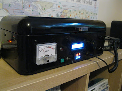
Just thought I’d let you know about a homebrew project I’ve just completed. I call it the Bread Bin 80 - you’ll see why!

It is a single band (80m) SSB transceiver that puts out 25-30W of clean RF. It uses the familiar pairing of Arduino Uno + Si5351 (with 16x2 LCD screen and rotary encoder for tuning). Other than this though it is largely an analogue beast - which I thought you might like!

I made my own double balanced mixers which work really well. But the Si5351 can’t generate the 7 dBm of local oscillator signal to drive them so I then had to build a simple one transistor RF amp for each clock of the Si5351. I even went above and beyond the call of duty and home-brewed my own IF crystal ladder filter (although this was actually a kit).

The rig has a three stage IF cascade amplifier with 2 back to back JFETs in each stage + AGC and analogue S meter. There is something very satisfying about seeing the needle bob about as you are listening. I also put in a switchable analogue audio filter in front of the audio pre-amp which cuts out some of the higher frequency noise on the band.

Overall I’m really pleased with the rig. I’ve been working stations all over the UK and into continental Europe and getting some great reports. Except the one guy (who shall remain nameless) who wasn’t the least impressed that I was working him on a homebrew rig: he was only keen to point out that my antenna must be far too low to give me such an attenuated signal!!! I guess you can’t please everyone.

Anyway, I’ve done a bit of a write up and included some photos (outside and in) on my QRZ page if you are interested:


Thanks for sharing your home brewing story about your short wave receiver on YouTube. I’ve enjoyed following that and seeing it progress. Those little ‘Altoid’ tins are great aren’t they.

Thanks again for all your encouragement through the Soldersmoke podcast. I really enjoy it.

Stay In The Shack!

73 from across the Pond.

Nick

M0NTV
Nick Wood


Designer: Douglas Bowman | Dimodifikasi oleh Abdul Munir Original Posting Rounders 3 Column