Mr. Carlson mentions that he is a ham radio AMer. He is also on SSB, but AM is, he says, his preferred mode. FB.
I got a real chuckle about the MVC switch position on the front panel. "Manual Volume Control" like "Manual Gain Control." I thought I had invented this term. You know, "real hams control their gain manually." This is why Farhan never put AGC in the BITX20. But it seems the Army Air Corps was way ahead of me with the BC-348.
Mr. Carlson makes it sound (!) like the Dynamotors are a thing of the past. Not true. Every Saturday morning I listen to the Old Miltary Radio Net and hear a number of Dynamoters spinning in the background. One belongs to Buzz W3EMB who uses a BC-348. Buzz has an SDR attached to the IF of his BC-348, which I think is an admirable mix of the old and the new. Those BC-348s are, after all, quite old. WWII old -- like 85 years old. And still working.
Paul has a good discussion of the importance of short lead length, and of mounting shielded capacitors properly, and of the usefullness of a good groundplane under the capacitor. Go Manhattan boards! Paul's presentation on how to identify the outside foil of a capacitor was very good, but I was wondering if you could also find out by using a file to remove some of the yellow insulation, then test with a DMM to see which terminal is connected to the foil.
"Lots of times you have to add solder to remove solder." Indeed.
The importance of testing for BOTH capacitance and leakage. Yes.
But why bother with "period correct" internal wiring harnesses, when you have already put a bunch of modern caps in there? I mean, I'm in favor of the re-capping, but this seems inconsistent with the need for "period correct" internal wiring harnesses.
When Paul first fired up the receiver, I was hoping he would disconnect the antenna to see how much band noise was getting through.
When Paul got to the IF alignment, he spoke of the dangers of working on energized high-voltage gear. I had been thinking about getting a BC-348 myelf, but Paul's comments reminded me of why this is probably not a good idea for me. Paul's comments about "knowing where your hands are" is on target. "One hand behind the back, " is a good rule for this kind of energized testing -- this will help prevent current from a mishap from flowing through your chest.
I may have more comments later. Off to the beach now.
Back from the beach:
"Contrary to popular belief, the simpler the receiver, the better they hear." Amen Mr. C.
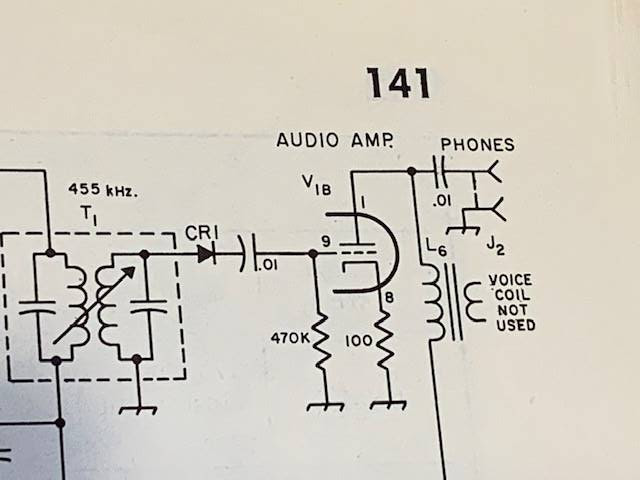
Paul's heroic cleaning of the 915 kc crystal made me feel like a wimp for not having tried to do this with some "bad" 455 kc rocks I was given while trying to build the Mate for the Mighty Midget receiver. I may go back to those crystals and try to clean them as Mr. C did.
The grand finale of this 2.5 hour video was, as expected, a demonstration of how good it sounds. But unfortunately it did not sound good. Paul tuned through the 40 meter band and I heard NO CW signals. I didn't even hear FT8. There were a few anemic SSB signals and, as he reached the upper portion of the band some very weak AM broadcast signals. I didn't even hear CHU Canada's time signal. Huh? Why? Our very simple homebrew Direct Conversion receiver sounds a LOT better than that. I mean look at the sweep of 40 meters that I did using only a simple dipole: https://soldersmoke.blogspot.com/2024/12/an-evening-bandscan-on-40-meters-using.html Why is there such a big difference in performance?
Could it be the antenna that Paul was using? He was on what he calls the 369 antenna. Could there be a problem in the receiver? Could it be band conditions?