AA1TJ writes: I spent most of a week working to raise the RF output power from my unijunction transmitter to nearly 1mW. I was rewarded this evening with two contacts.
Jim/W1PID exchanged (599/449) signal reports with me from Sanbornton, NH (112km) at 2210z!
Dave/K1SWL did the same (589/229) from Newport, NH (95km) some four minutes later!
I should think these were the first-ever radio contacts made using a unijunction transistor as the transmitter.
FYI: my receiver was comprised of a single 1N34a germanium diode mixer followed by a single 2N35 germanium transistor audio amplifier. Great signals on this end.
I've wanted to change the VFO in my R2 phasing receiver. The AD9850 DDS VFO with a divide by 4 I-Q generator limited me to 160, 80 and 40 meters. But an Si5351 chip will go up to 160 MHz. With a divide by 2 I-Q generator, this should allow me to cover 160 through 6 meters. I got the Arduino, LCD and rotary encoder all working tonight. Thanks to Thomas LA3PNA for the code, and to Tom AK2B for help with the Arduino. The Si5351 board that you see sitting atop the Arduino is the work of Dean AC9JQ. Thanks Dean.
The flip-flop and inverter IC's should arrive this week. That will allow me to finish up this VFO conversion project.
Daniel HK4DEI wrote to report that page 149 of the SolderSmoke book was providing some solace and comfort as he struggled to get his version of Peter Parker's Micro 40 Double Sideband rig going. He was having problems with the amplifier. He was almost at the point of sacrificing chickens to Papa Legba. I wished him luck and told him to hang in there.
Elisa saw my e-mail to Daniel and complained that I hadn't given him the solution to his amplifier woes. I tried to explain to her that there are sometimes things in this universe that are just UNKNOWABLE. C.F. Rockey W9SCH (who alerted us in SPRAT 22 to the chicken sacrifice option) spoke of transistors that exhibit "quantum mechanical necromancy." Rockey explained that when this happens, "The transistor simply turns up its toes and dies. Not even an Atomic Physicist can tell you why!"
But Daniel persisted. And he won the battle:
Hey Bill
Did you kill some chickens already? If you did, THANK YOU! If you don't, then please enjoy a nice sancocho de gallina for me.
But seriously... guess what?
FAKE TRANSISTORS!!!!
I knew I couldn't be screwing everything up so badly and VK3YE's circuit couldn't be so wrong.
I was getting nuts trying to understand why it wasn't working, changing a single inductor could fry the final instantly or not getting any power out at all (?) also my final BD139 was getting extremely hot, and many of them died with no apparent reason (Page 149!!!!).
I ordered a "good" deal of BD139's and BD140's combo for an incredible low price from [A WEB SITE], I've ordered many *apparently good components from that site with no problems so far... mainly resistors and capacitors. Having tried everything to get my circuit working and after some quick online search about fake transistors from china my suspicions grew considerably and I remembered some -other- BD139's I had ordered from Amazon some time ago.
I proceeded to solder the new transistors in place in my PA and Bingo! No more heating of the final and about the expected 0.5W out from my first DSB homebrew rig. I quickly reported to a fellow homebrewer in a local net and the report was amazing! 59 +10, the final transistor was comfortably warm to the touch and my mind could finally rest... lesson learned! What an electromagnetic achievement!
Just wanted to share my success Bill and thank you again for you book and you kind response.
Please say hi to Elisa and the Cristalinhos from a fellow Latin friend.
Michael updates Peter (and us!) us on his efforts of this week:
Grüss Peter!
Thanks for the nice message. Yes, I knew that you were going to be QRV with your ZnO transceiver but I never heard if you had made any contacts. I guessed that you had not, otherwise I'm sure you would have let me know.
Again, I think your circuit looks really great! It's amazing to think you managed to squeeze 500uW from a scrap of oxidized zinc-plated steel. Even if you didn't make a contact, what you are doing is really fantastic. Congratulations on the creation of this amazing radio!
Okay, so I spent most of the afternoon at the workbench. Thus far I'm only using a single SRD (step-recovery-diode...1N5401 rectifier). Of course the result is a unipolar pulse. The idea did work as planned, however the power only increased by 2.24dB. The maximum RF output power is now 230uW. At least the SRD makes a pretty pulse :-)
Please find two scope captures attached to this message. The first (0002) shows the SRD generated unipolar pulse. As you can see, the pulse width is nearly perfect for the job. The second trace shows the output RF waveform. The worst spurious energy is ~20dBc. The second image shows the 507kHz waveform at the unijunction emitter along with the output RF waveform.
The beacon is presently off the air, but I look forward to trying my luck tomorrow with a back-to-back pair of SRDs. A bipolar pulse pair will provide a shock impulse once every 3.5 cycles, instead of once every 7 cycles with the present unipolar drive pulse. The bipolar pulse pair should result in increased RF output power as well as a slight spectral improvement.
It's only a matter of time before you make a ZnO QSO, Peter. As we always say, the difficulty merely sweetens the eventual success.
A broadband measurement of my output power (using an AD8307 log-amp power meter) indicates 139uW. Spurious frequency energy accounts for 2uW, leaving 137uW at 3.552MHz. I believe this is roughly the output power produced by your ZnO transmitter?
This morning I'll attempt to increase the unijunction (UJT) 80m RF output power by inserting a pair of back-to-back standard-recovery power supply rectifiers (1N5401-ish) at the UJT base-2 to ground node. Thus far I have relied exclusively on internal UJT nonlinearity for the generation of harmonic energy. I've reason to believe the minority carrier charge-storage capability (normally a defect, but hopefully a virtue here!) of these rectifiers will efficiently produce a bipolar pulse-pair every 1/500kHz seconds resulting in an odd-order comb-spectrum. At least that's the plan...we'll see how it works out ;-)
Peter, I never heard the results of your ZnO DXpedition? Any luck OM?
Okay, I'm off to the Hobbit-Hole. My heartfelt thanks to you all for your shared interest in this cock-eyed project.
73,
Mike, AA1TJ
Peter, DL3PB, in Germany respond with amazing news of his own. Peter is homebrewing his own tunnel diodes, using Zinc Negative Resistance Oscillators. No store-bought appliances for him!
At this point you really have to visit the pages of Nyle K7NS
Nyle tells of building a little microwatt transmitter, and, once the snow melted, climbing a hill 5 miles from town to see if he could hear it. This reminded me of young Marconi's early efforts in Bologna.
Peter writes:
Hi Folks,
Mike, your plan on how to increase output-power sounds reasonable – yes, a few dB could really help, to make reception a bit steadier and thus allow a QSO.
Well, I thought we had already talked about the ZnO TRX attempt, but obviously we didn’t. The reason is dead simple - It didn’t work.
[ The ZnO TRX is a minimalist 80m band transceiver with a homemade tunnel-detector-diode as the only active device – based on Nyle’s K7NS experimentshttp://sparkbangbuzz.com/zinc-osc-2/zinc-osc3.htm – please find attached an early schematic ]
Three days in a row after Xmas I tried for several hours each, I had announced the activity on QRPSPOTS and the German QRP Forum. Thus several guys within the right distance were really trying hard to copy. I used different temporary antennas, mostly verticals, but also a sloper dipole - nada, niente , nothing. One or two OMs reported weak CW signals on the scheduled QRG, but too deep in the noise, to even make out, whether it was me or someone else.
Yes, power is more or less comparable, actually it’s 0.5mW +/-3dB depending on the day’s form of the homemade tunnel-detector, but I guess all my antennas are some dB behind a full-size dipole, so at the end it’s pretty much the same.
Folks were very cooperative during the test itself, but after it was clear, that it had not worked, the usual trolls showed up to explain, why that never could have worked... I plan another test within the coming week e.g. during the PA-contest next weekend ( I’m only 30km from the dutch border ) with a base loaded 15m vertical – be assured, you’re the first to hear about any success in terms of QSO or just being heard anywhere.
What would we go for, if everything works as expected and/or right from the beginning – or as Jim said it : What fun...
73!
Peter/DL3PB
Finally, Alan Wolke provides a very illuminating (as always) explanation of tunnel diodes):
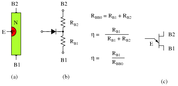
AA1TJ reports: Breaking news from W1PID... "Mike! I just copied the beacon. I got 'VVV de AA1TJ 150 uw' and it faded out. 2146Z on 3551.95MHz" That's it! Jim copied a message produced by a lowly unijunction at a distance of 112km. How's that for cool!In a nutshell... the unijunction runs as an R-C relaxation oscillator at ~500kHz. A quartz crystal at the emitter frequency-locks the sawtooth waveform to 507kHz. The 7th harmonic is admitted to the antenna via a bandpass filter. The RF output to DC input conversion efficiency is all of 0.1%. Heat-sink? Check! Mission statement: "...to boldly go where no unijunction has gone before." Cheers, Mike, AA1TJ I think the really cool thing is that EM waves are once again flying out of the Vermont Hobbit Hole, propelled into space by the poet laureate of QRP.
QST de AA1TJ... I've a 150uW transmitter built from a single unijunction transistor currently running as a beacon on 3552kHz. If my New England amateur radio pals would be so kind as take a listen for it I'd be most appreciative!
We are honored to induct Alan Wolke W2AEW into the Colorburst Liberation Army. And for his valiant effort to build and explain a MMM Low-Pass filter, he is immediately promoted to the rank of CBLA Two Star General. Congratulations General Wolke. As is the case with all of his videos, this one has already had an impact far and wide. Ian writes from far-off Western Australia:
Jan 27 at 6:19 PM
G'day Bill,Just in case none of your other correspondents have brought it to your attention, here is a great video W2AEW has put up showing really clearly the positive effect of a low pass filter on the output of the Michigan Mighty-Mite.
It made me appreciate the benefits of an LPF more fully. It's always been clear to me that the harmonics would get rolled off, but in my head I hadn't made the connection between that and the improvement to the beautiful smooth sine wave that we are working towards.
Anyway, I thought you, and your mate Steve "Snort Rosin" Smith may be interested.
Thanks to you and Pete for Soldersmoke, I'm sure you're responsible for keeping the flame alight in many a ham.
73,Ian VK6MIB
And Steve "Snort Rosin" Smith, the guru of low pass filters, observes:
Of course, to work properly in the land down under, the inductors must be wound in the opposite direction as those in the Northern Hemisphere :-P .
Seriously, there is a lot to be learned from the lowly Mighty Mite especially regarding impedance matching; not to mention LC circuits, link coupling, amplifiers, oscillators, etc. . What fun!
Sometimes the Radio Gods conspire against you. Check out the chart above. It shows relative humidity at my location. I zapped my LCD display right around 2000 UTC on January 25, 2016. That poor little LCD didn't stand a chance :-( Right now relative humidity here is 79%. No sparks now! I like the solution (!) proposed by Brendan, EI6IZ: You can get an anti-static spray designed to treat carpet, upholstered furniture etc. This is a sensible thing to do if one tinkers with electronics and for the average hamshack a bottle will last for many years as it only needs to be applied lightly and infrequently. For example http://ie.rs-online.com/web/p/esd-safe-clean-room-treatments-lotions-dispensers/0182893/ For cheapskates however, diluted fabric softener sprayed on the carpet and chair will work well for at least a few months but will require much more frequent application than the 'proper stuff'.
I give my car seat an occasional squirt in dry summers to stop the 'zap' when getting out on a dry day.
After the big East Coast blizzard, the atmosphere in my ham shack became very dry. I sit in one of those desk chairs with little plastic wheels. The shack is carpeted. So when I roll from operating bench to workbench, the chair, the carpet, the dry air and I all become a kind of Van de Graaff generator. Yesterday, my hand brushed against the 16X2 LCD display on my new R2 phasing receiver. The pretty glowing numerals in that display disappeared in a small spark, never to return. I swapped out another display I had, so all is well. But the repair was a pain in the neck, involving the soldering of some 16 LCD pins, so I don't want to do it again. I consulted with Pete Juliano N6QW who told me that this kind of LCD carnage is quite common in dry environments. He said he had cured the problem by placing a small piece of Plexiglas in front of his displays. This got me thinking about those static protective bags that Digikey uses when shipping many of its components. Might the material from these bags prevent the loss of another display? I retrieved a couple of these bags from the garbage and did a little test: First, I rolled across the shack in the chair with a small screw-driver in hand. At the other end of the shack lies my well-grounded DX-100 transmitter. I moved the screwdriver close to the metal on-off switch. SPARK! It was visible, and quite audible in the AM broadcast receiver nearby. Next I taped a small piece of this material over the switch and repeated the ride in the chair. No spark. Nada. I repeated this several times and always got the same result. It appears that the material in the bag helps dissipated the static discharge over a wider area, preventing the spark. I quickly taped a piece of this material over the two LCD screens in my shack. It's not pretty, but it is temporary, and cheaper than a humidifier. I'm not going to try this on the actual screens, but I do think these small pieces of material will help prevent another accidental frying of an LCD display. Here is the Wiki on anti-static bags: https://en.wikipedia.org/wiki/Antistatic_bag And here is the data sheet on the bags that I am using: http://documents.staticcontrol.com/PDF/Static_Shielding_Bag_1000_Series.pdf
I found this today while rummaging around in the shack. It is starting to fall apart so I figured I better digitize it before it turns into dust.
July 24, 1936. 7 am in Central Germany. 29.0 degrees Centigrade. Clear skies? German Shortwave Receiving Station DE 2518/F monitored W5AIR's contact with Irish station EI7F on 20 meter CW. The receiver was an OV2 Schnell tube (almost certainly a regen) fed by a 38.5 meter long antenna.
Conditions must have been pretty good -- they were approaching the peak of sunspot cycle 17.
In 1954 W5AIR was assigned to Garold D. Sears. He was probably the operator.
I'd been meaning to build a proper cover for my improvised 160 meter L network. The approach of Winter Storm Jonas pushed me into action yesterday afternoon. First I mounted the variable cap (from an old Johnson rig) and the roller inductor on a suitably sized piece of wood:
Then I put the tuner inside an old cooler. I drilled holes in the bottom for the coax and the antenna wire and the ground.
Here it is at the feed point. Pretty cool, don't you think?
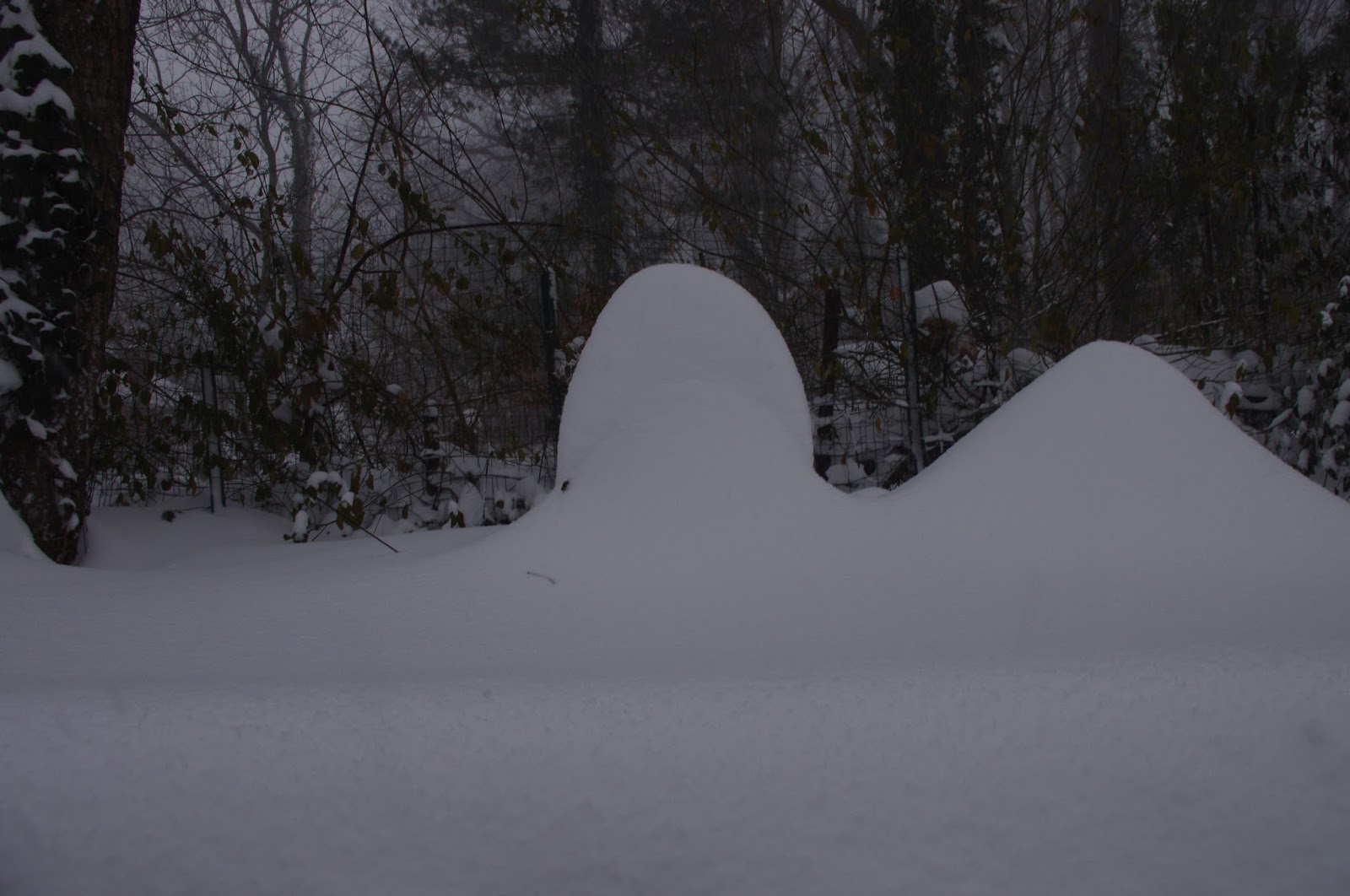
And here it is 24 hours later:
The blizzard has been quite impressive. Early this morning it featured lightning and thunder!