Podcasting since 2005! Listen to Latest SolderSmoke

Sunday, March 20, 2022

17 - 12 Dual Band SSB Transceiver On-The-Air


It is still completely al-fresco, with all the guts exposed, but I got it on the air this morning.  I was 17, running it through my CCI  .1kW  100 watt amp to a tuned doublet.   Four QSOs so far: HP3SAM, K5BM, N4ZUL, and II3WRTC.   

The structure of the rig is basically BITX. 

The blue boards you see are TIA boards developed by Todd K7TFC. 

No major problems to report.   I will try it out on 12 meters  soon.  The receiver was working well on that band. 

Flick Lives -- More from a Great Web Site about "Jean Shepherd"


Jim Clavin has some really great stuff on his FlickLives website: 

Much of this stuff I had never seen.   Like the picture he has of young Shep in his shack.  I wonder how old he was in this picture.  He appears perturbed.  Perhaps his Heising Modulator was distorting?

Jim dug up all of Shep's licenses and got the names and callsigns of all the hams who were active from Shepherd's  hometown during the years Shep was living there.  I think I can recognized some of the names -- Shep talked about some of these guys when talking (on WOR) about ham radio.  Boles.  Stan.  Good times. 

The CQ Guest editorials and the various articles are a lot of fun.   Some things never seem to change. 

Thanks Jim! 

EXCELSIOR! 

Friday, March 18, 2022

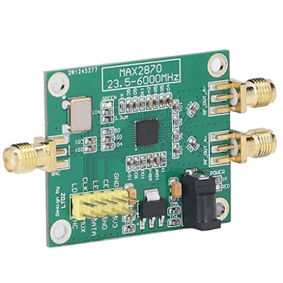
Help! Can You Write the Software to Control the MAX2870 Board?

 
It is not every day that you get the chance to help a master homebrewer like Pete Juliano N6QW.  But today is just such a day.   Pete asks for some coding help: 


The Radio Gods would be pleased if you help.  The Mojo and Juju levels of all your projects would increase.   If you can help, please do so.  

Thursday, March 17, 2022

Colin M1BUU's Homebrew Manhattan SST


Wow, especially on St. Patrick's day I think it is appropriate to say " 'tis a thing of beauty. "

Colin did a great job on his homebrew version of the SST transceiver. It looks like his is on 30 meters.   I especially liked his description of the troubleshooting that followed the construction.  the assist provided by AA7EE's blog was especially cool, and demonstrates the long-lasting power of internet-shared tribal knowledge. 

Colin wrote (on Facebook):  

I was inspired by Bill and his adventure with the SST-20, so I started gathering a few parts last year to build a Manhattan SST. I did a joint SOTA activation with a fellow homebrewer ham at the end of January and we started talking about classic portable CW rigs, it turned out that we both had an SST build on our 'list'. I was challenged to build the SST for the next joint SOTA activation!
It took a lot of effort and a few late nights but I did manage to produce a rig capable of making QSOs for a joint SOTA activation of Fair Snape Fell, G/SP-007. I'd done a solo activation of Pendle Hill G/SP-005 a few days before with the rig for a trial run and I discovered that the AF was very low. After some troubleshooting I noticed that I'd soldered the LM386 gain set capacitor to an incorrect pad. Doh! I fixed my error and the rig had much more gain.
I found that with the improved AF gain, the rig would squeal if the gain was turned up. I was ready to give up really, but after a cool off period, I began researching the issue and it turns out that it's very common and indeed I found posts from 1997 about it! It seems as though my recreation was so faithful to the original, I'd included the original flaws too! I added in a 0.1uF cap and resistor connected to pin 5 of the AF amp chip as per the suggestion on Dave AA7EE's blog and now the squealing has stopped.
I'd made 14 QSOs during the joint SOTA activation, so I considered my challenge to have been met! It's been a bit of an epic build!
73, Colin, M1BUU


Wednesday, March 16, 2022

Pete N6QW Looks at Tapped Capacitance Impedance Matching


For some reason we are more accustomed to impedance matching using tapped coils than we are with the use of tapped capacitors.   This is too bad because tapped capacitors are a very useful impedance matching tool.  Pete recently looked at this technique.  Check it out: 


Tuesday, March 15, 2022

VK2BLQ's Two-Tube Regen with a SolderSmoke Dial


Thanks to Peter Marks VK3TPM ("a bloke with too many hobbies") for alerting us to this magnificent homebrew receiver with the especially magnificent tuning dial.   

We have used old CDs as dials for many years.  I have one on my Q-31 Quarantine SW receiver.  But never have we seen one with SolderSmoke emblazoned on it. FB OM. 

Stephen VK2BLQ should make sure that those 6U8s haven't gone old on him.  I recently replaced the 6U8s in my Mate for the Mighty Midget with 6EA8s.  This seemed to rejuvenate the receiver.  

Also, it is shame that Stephen doesn't keep that rig at 12 volts.  250 V?  Yikes.  As I often say, you CAN hurt yourself with 12 volts, but you really have to work at it.  Not so with 250 V.   One hand behind your back Stephen! 

Thanks to Peter and Stephen. 

Monday, March 14, 2022

Sunday, March 13, 2022

Video #3 17/12 Transceiver -- Receiver is Working on 12 and 17 meters (Listen! Video!)


Here is an update on the 1712 transceiver project. The receiver circuitry is done and I can listen on 17 and 12 meters. In this video I was using my 75 meter doublet tuned to 17 meters (reception on 12 was pretty good using this antenna). As you can see, I found a temporary solution to the VFO dial problem -- I am using the cardboard tube from a coat hanger super glued to a knob. The tube fits snuggly over the shaft from the VFO assembly.

Hans Summers' QRP Labs Bandpass Filters:


Thanks Hans!


Wednesday, March 9, 2022

Video #2 17/12 SSB Transceiver -- Receive RF Amplifier Needed?


Lots of progress to report on the 1712 rig. 

With just two TIA amps (one on either side of the 10 pole filter) and the AF amplifiers, I now have it inhaling on 17 meters.  But nothing heard so-far on 12. On both bands I can hear the band noise, but just barely.  So I may try some RF amplification ahead of the mixer. What do you guys think about this? I think the two TIAs and the crystal filter are providing 30 db of gain.  

I want to get the receiver circuitry working well on both bands before I build the T/R and transmit amplifier circuitry.
  
It is nice to have a project on the bench!  

I am trying to find a shaft extender or adapter for that big beautiful HT-37 main tuning cap.  The shaft on the capacitor has a width of 1 cm or 0.393701 inches.  I need something that will grab onto that and allow for the connection of a tuning knob.  Please search your junk boxes!  

Tuesday, March 8, 2022

Tuesday, March 1, 2022

Dennis WC8C's FB Homebrew 6 Meter Rig -- Any Ideas or Suggestions?

 
Dennis WC8C is the event coordinator for the radio club in Michigan that I recently spoke with.  He mentioned to me that he was working on a homebrew 6 meter rig.  FB Dennis.  I see lots of tribal wisdom in your approach, especially in your decision to do this in a stage-by-stage modular form. 
Dennis's rig is obviously a work in progress, so if anyone out there has any helpful hints (especially on the carrier suppression and on the testing for spurs and splatter) please share them with him via e-mail or blog post.  

The files on Dennis's rig are on GITHUB: https://github.com/soligen2010/6_Meter_Transceiver

Thanks Dennis!  
----------------

This is my 6 Meter homebrew transceiver, currently work in progress.  It is a single conversion super –heterodyne design.  I constructed each stage independently with SMA connectors.  This is so I can re-make sections as needed, and will allow me in the future to swap sections to experiment with alternate designs.  The VFO and BFO are controlled using a SI5351 with an Arduino micro controller.  I currently have separate SI5351 modules for VFO and BFO because I suspected issues with cross-talk.  These issues may not actually be real, so once I am happy with the performance, I will test again with just one module to see if it is OK.  The Power Amp is still on the to-do list, so output is well under 0 DBm

The Blue boards were designed by me and ordered on-line.  The other boards I etched myself.  Construction is mostly surface mount because I find it easier than drilling all the holes.  SMD components are mostly 805 and 1206 size. Transistors are SOT23.

The Band Pass filter is a 5 coil design made with air-core inductors.

3 bi-directional termination insensitive (TIA) amps are used (blue boards).  Total RX gain is about 44db.  Total TX gain is about 16db.  Each board has its own independent RX/TX switching circuitry (mosfet based) and is fed with +12.5, GND, and RX/TX logic signal from the Arduino (3V logic and up will work)

The Mixer and modulator are both Diode Ring mixers.

The 12 MHz SSB filter is a crystal ladder filter similar to the one used in the uBitx.

The Mic and audio pre-amp (also a blue board) is made on a modified TIA amp board.  I had 10 of these boards made, and the needed circuitry was largely the same, so I modified the board with a rotary tool and jumpers.

The Audio amp is a PAM8403 module and drives a headset.  I did make some modifications to the module so it runs in-spec and to eliminate the power on audio pop.

The challenges I have been having are mostly related to spurs, splatter, carrier suppression and TX audio quality.  I have been gradually tweaking these things to improve operation before I start on a power amp.  My IF is 12 MHZ, and I was using the LSB side of the crystal filter because it is sharper (VFO 62 – 66 MHz) but have recently changed over to the USB side of the filter (VFO 38 – 42 MHz).  This eliminated the spurs I was seeing near the pass band.  I still need to make some adjustments to the crystal filter as it is too broad.

I still have some splatter and audio quality seems low, but I am starting to doubt my test setup.  I see the splatter on the RTL SDR, but I don’t see it on the Tiny SA.  The spatter happens at ~160 KHz intervals.  I am hoping to find someone local with a better spectrum analyzer to help me verify if it is the rig or my SDR dongle/test setup.

The modules to the side of the picture are my rejects/experiments.  The one covered in copper shows how I eventually will shield all the modules.  I 3D printed a cover for the board, when wrapped it with copper tape, soldered to the bottom ground plane.  The one shown is a diode ring modulator.  For some unknown reason the carrier suppression is rather poor.  I had previously made a junk-box modulator that had much better carrier suppression.  I don’t know why it is better than the one I more carefully made for the radio, but until I figure it out, I am using the junk box version.  The junk box modulator uses unmatched schottkey diodes, whereas the “final” one uses a 4 diode SMD package because I wanted them matched – I thought this would be better, but maybe not.

Designer: Douglas Bowman | Dimodifikasi oleh Abdul Munir Original Posting Rounders 3 Column