Podcasting since 2005! Listen to Latest SolderSmoke

Showing posts sorted by relevance for query SST. Sort by date Show all posts

Thursday, March 17, 2022

Colin M1BUU's Homebrew Manhattan SST


Wow, especially on St. Patrick's day I think it is appropriate to say " 'tis a thing of beauty. "

Colin did a great job on his homebrew version of the SST transceiver. It looks like his is on 30 meters.   I especially liked his description of the troubleshooting that followed the construction.  the assist provided by AA7EE's blog was especially cool, and demonstrates the long-lasting power of internet-shared tribal knowledge. 

Colin wrote (on Facebook):  

I was inspired by Bill and his adventure with the SST-20, so I started gathering a few parts last year to build a Manhattan SST. I did a joint SOTA activation with a fellow homebrewer ham at the end of January and we started talking about classic portable CW rigs, it turned out that we both had an SST build on our 'list'. I was challenged to build the SST for the next joint SOTA activation!
It took a lot of effort and a few late nights but I did manage to produce a rig capable of making QSOs for a joint SOTA activation of Fair Snape Fell, G/SP-007. I'd done a solo activation of Pendle Hill G/SP-005 a few days before with the rig for a trial run and I discovered that the AF was very low. After some troubleshooting I noticed that I'd soldered the LM386 gain set capacitor to an incorrect pad. Doh! I fixed my error and the rig had much more gain.
I found that with the improved AF gain, the rig would squeal if the gain was turned up. I was ready to give up really, but after a cool off period, I began researching the issue and it turns out that it's very common and indeed I found posts from 1997 about it! It seems as though my recreation was so faithful to the original, I'd included the original flaws too! I added in a 0.1uF cap and resistor connected to pin 5 of the AF amp chip as per the suggestion on Dave AA7EE's blog and now the squealing has stopped.
I'd made 14 QSOs during the joint SOTA activation, so I considered my challenge to have been met! It's been a bit of an epic build!
73, Colin, M1BUU


Thursday, May 20, 2021

The SST QRP Transceiver

 
Click on the schematic for a better view

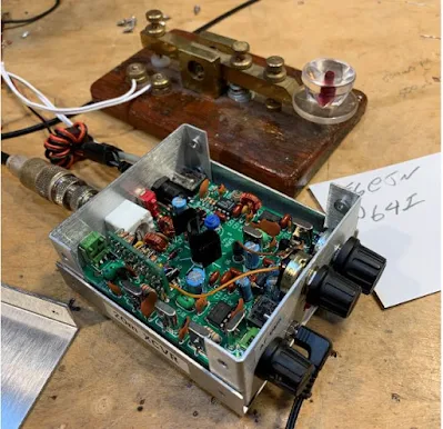
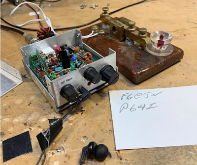
Bob KD4EBM recently sent me an amazing package of radio goodies.  Included was a little metal box not much larger than a deck of cards.  It is a 20 meter SST transceiver designed by Wayne Burdick N6KR during the late 1990s.  This transceiver is built around three NE602 Gilbert Cell mixer chips.  It arrived in my shack as I was struggling to understand the Gilbert Cell.  TRGHS.  It also put me back on the path of QRP CW righteousness.    Thanks Bob.  Thanks Wayne. 

I e-mailed Wayne Burdick (now of Elecraft fame) to tell him I was now using the rig he had designed so long ago.  Wayne e-mailed back, saying that the SST was the smallest "real" radio that he had ever designed.  SST stands for Simple Superhet Transceiver

I've been using the SST every day for the last week or so.  It is a pleasure to operate.  I'm using it with the key from India that Farhan brought for me.   It is truly QSK -- the receiver stays on when I transmit.  I've never used a QSK rig before and I can now see the big advantage that this provides:   When I am responding to a CQ, I can immediately hear if the other guy put out another CQ or respond to someone else -- I can stop calling at that point.  My first contact with it was with F6EJN.  Again, TRGHS. 

I made two small mods to the SST:  I added 1 uH to the RFC in the VXO; it  now tunes 14.053 -- 14.063.   And I took out a noise blanker that had been installed. Removing the noise blanker left an ugly hole in the front panel which I promptly filled with a completely cosmetic machine screw. 

Here's the manual:

https://qrpbuilder.com/wp-content/uploads/2017/04/sst_manual_042217.pdf


Friday, May 21, 2021

AA7EE's Amazing Homebrew SST QRP Transceiver


Look at that rig.  It is truly a thing of beauty.    

I was very pleased to see Dave AA7EE's comment on my SST rig.  This caused me to search his site for his SST article.  And wow, it is an SST treasure trove.  Lots of discussion of the circuit and mods. And Dave's usual wonderful photography and videography. 

Check it out.  

https://aa7ee.wordpress.com/2016/09/09/a-scratch-build-of-n6kr-and-wilderness-radios-sst-for-20m/

Thanks Dave! 


Wednesday, September 8, 2021

SST -- QRP On The Beach


Up in a beach house on Cape Cod Bay in Massachusetts, I put the SST on 20 meters using an End-fed Half Wave antenna and QRP-guys tuner.  Conditions were pretty bad, with solar storms causing disturbances in propagation, but I did manage to get picked up by RBN skimmers in Iceland, Germany and Italy (see below).  And I had one nice QRP-QRP contact with DK4AN.

I was having trouble getting out until I used the oar to raise the central portion of the half wave antenna -- that's where the current is. 

Thanks again to Bob KD4EBM for sending me the SST.  


Saturday, June 26, 2021

SolderSmoke Podcast #231 -- Travel, SST, Mythbusting, Filters, TIAS, NanoVNAs, DC RX in SPRAT, Drake A Line, Spillsbury, STICKERS! Mailbag


SolderSmoke # 231 is available: 


Annual Field Day Special Edition

Travelogue:   To the Dominican Republic! 
New dog -- Meet Guapo (see below). 

A great Father's Day for Pete and Bill.  I got a TinySA. 
Pete got some cool chick magnet glasses (see below).  
Watch out Newbury Park! 


Bill's Activity

SST Transceiver. Took it to Dominican Republic.
Made only one contact, but QRP-QRP. 
Not a lot of CW activity, and not a lot around 14.060. 
A lot more FT8 visible on the NA5B WebSDR.
That might be better for this kind of operation.  
I might try SST CW out today from the backyard. Field Day!

Fired up my 20 meter DSB NE602 rigs.  Made two contacts.  
Still trying to fully understand the NE602 Gilbert Cell.  Lots of mystery in there. 

Building "The MythBuster."  75/20 with sideband inversion.  

10 pole 5.2 MHz filter.  Used Dishal and AADE. 
Used NanoVNA to see the passband. 
G3UUR for crystal parameters.
Cohn Constant K topology. 

Also used NanoVNA to check input and output impedance on the TIA amps I will use around the filter. 

Pete's activity: 

Article on DC receiver in SPRAT. FB response. 50 receivers under construction.   

Work on Drake A Line.  

Jim Spillsbury. 

------------------------------

The N5JHH IBEW SolderSmoke stickers (see above and below).  How we will use them. 

Mailbag:
N2SVD
K8ITY
Tom (Junkbox receiver)
N0ZIB (Curse you, SolderSmoke!) 
DL6ID
N2NLY
VK2EMU
ZS1KE
AF7O
NG2E
VU2ESE
OK1RP
N5JHH


Saturday, May 22, 2021

Monday, June 14, 2021

Santo Domingo Shack on 12th Floor Balcony -- SST QRP CW


June 2021.  We were in Santo Domingo, Dominican Republic.  At this point we were in a 12th floor apartment in the center of the city.  I would take my SST 20 meter CW transceiver and EFHW antenna out on the balcony.  I made no contacts from this location, but one of  my CQs was picked up by K9TM on the Reverse Beacon Network (see below).  All the other RBN spots were the result of calls from the eastern tip of the island. (Click on the RBN image for a clearer view.)


Saturday, December 18, 2021

On 17 meter CW from Santo Domingo with a uBITX


We are up on the 12th floor of a building in Santo Domingo. I brought my uBITX and managed to check in as baggage a 16-foot crappie fishing pole. I figured I needed to get the 1/2 wave antenna away from the building -- last time I was here I was unable to make any contacts from this location with the antenna stretched along the balcony. Last time I was QRP with an SST transceiver. 

The fishing pole worked well, but I operated with fear that it would fall or that the neighbors would complain). Today I got on 17 CW with the uBITX (more power than the SST), put it on 17 CW and promptly worked W4A, a special events station commemorating E. Howard Armstrong.  Turns out that today is Armstrong's birthday.  TRGHS.  

On the Reverse Beacon Network my CQs were heard by KO7SS in Arizona (very cool skimmer station at 8100 feet!) and by W2NAF (interesting operations in Antarctica, Svalbard and Virginia Tech). 


Sunday, May 30, 2021

QRP - QRP Contact from Dominican Republic


It took some brass pounding on my homebrew key, but on May 28, 2021 I made a real QSO from the eastern tip of the island of Hispaniola.  KJ4R came back to my CQ near 14.060 MHz. I was running just 1-2 watts from my SST transceiver to an end-fed half wave antenna. Ed KJ4R was in South Carolina running 5 watts, also to an EFHW antenna.  TRGHS.  Thanks Ed.  And thanks to Bob Scott KD4EBM and Wayne Burdick N6KR.

Wednesday, October 13, 2021

SolderSmoke Podcast #233: PIMP, Boatanchors, Novices, MMM, Heathkits, DC Receivers, Mailbag


SolderSmoke Podcast #233 is available. 

http://soldersmoke.com/soldersmoke233.mp3

Travelogue: Cape Cod. SST. Marconi Site.

The WFSRA:   The World Friendship Society of Radio Amateurs.


Pete's Bench:

The Pimp.
The NCX rig.
The Collins.
The many DC receivers built worldwide.
The parts shortages are real! Several key radios on hold. Si5351 sub.
Talk to G-QRP convention

Bill's Bench:

FT-8. Not for me. I tried it.
Novice Station Rebuild.
Globe V-10 VFO Deluxe.
Selenium rectifier removal CONTROVERSY?
Not crazy about my Novice station. Not crazy about CW. 
Mate for the Mighty Midget. Again. 
Mike W6MAB -- Detector problems LTSPICE Check
One more mod for MMM RX. Ceramic filter at 455.
Dropped screw inside tubular cap on Millen 61455 transformer. 
Talk to the Vienna Wireless Society
Thinking of a Moxon or a Hex beam.


BOOK REVIEW Chuck Penson WA7ZZE New Heathkit Book. http://wa7zze.com


Mailbag

-- New SPRAT is out! Hooray!
-- Todd K7TFC sent me copy of Shopcraft as Soulcraft. FB.
-- Dean KK4DAS building an EI9GQ 16 W amp. FB.
-- Jack NG2E Getting close on Pete's DC receiver.
-- JF1OZL's website is BACK!
-- Tony K3DY sent link to cool books. 
-- Sheldon VK2XZS thinking of building a phasing receiver.
-- Peter VK2EMU has joined the WFSRA. FB!
-- Ned KH7JJ from Honolulu spotted the Sideband Myth in the AWA video.
-- Chris M0LGX looking at the ET-2, asks about the variometer.
-- Pete Eaton Nov 64 anti HB rant in november 1964 QST. Wow.
-- Josh Lambert Hurley spreading FMLA stickers in the UK. FB
-- Stephen VE6STA getting ready to melt solder.
-- Got a great picture of Rogier PA1ZZ back on Bonaire.
-- Farhan reading the manual of Hans's new digital rig.
-- Paul G0OER wonders if FMLA getting ready to move on 5 meters.

Saturday, May 15, 2021

SolderSmoke Podcast #230 is available! Apr 1, Mars, Group Build, SDR, SSB, Mich Mighty Mites, Mailbag

SolderSmoke Podcast #230 is available for download

http://soldersmoke.com/soldersmoke230.mp3

N2CQR was down for maintenance 
A few words about April 1
China lands on Mars
Brood X Cicadas arriving in NOVA 

Pete's Bench
The Dentron Project
The Spillsbury Tindall SBX-11A
KK4DAS and the Simple SSB Group Build
TenTec mods
Shack Mystery solved.  Maybe 
Changing the channels at age 9 

Bill's Bench
Why LSB below 10 MHz? The "SSB Legend" Rig
WU2D RTL-Dongle Up converter
Understanding the Gilbert (Jones) Cell
SDRSmart  RTL-SDR.com V3 Dongle 
VK3HN and 2 meter SSB
Jack NG2E, MMM and the 10 minute transmitter
KD4EBM sends me SST by Wayne Burdick. DX!  
A new computer 

Mailbag: 
MM0ACN
VK2EMU
N5VZH
VE3KZJ
HS0ZLQ
AD0JJ
VK8MC
KK0S
VE3VVH
KB3SII
WA9WFA
M0NTV
W2DAB


 60 Minutes Story on Mars Ingenuity Helicopter: 

Thursday, February 25, 2010

Reverse Polarity Protection -- Words of Wisdom from K7QO

Words of wisdom from Chuck Adams, K7QO:
Wednesday, February 24, 2010 12:11 AM
From:
To:
qrp-l@mailman.qth.net
This posting due to the traffic on the SST reverse
voltage application.

Here is what I do. There is a diode, the 1N5817,
a Schottky Diode. Will take 20V peak reverse voltage,
will handle 1A continuous with 25A surge and has only
a 0.45V forward drop and the reverse current is 500uA.

I put one of this in series with the 12V line input of
every electronic device I build. If the designer used
a 1N4001-7 in series, I replace it.

I am not a fan of the diode across the voltage input
line and having it short out when reverse voltage is
applied. What if the applied voltage is a gel-cell
without a fuse? You blow the diode and you blow the
rig. IMHO is this not an ideal way to do it. Should
be using fuses too, but I don't. Haven't found a way
to use the flat auto fuses with gel-cells in a handy
low-profile way and inexpensive parts. I'd appreciate
the education, if someone has film and photos of great
arrangements.

I buy the diodes from Mouser.Com for about $26 per 250.
For a dime a rig it is a real cheap way to protect your
equipment from yourself and others.

With the limit of 1A at 13.8V, it is well within the
QRP operating limits. And why do you need more than
1A anyway?????? :-) And the low forward voltage
drop
means that the finals (which are usually fed
direct from the B+ line anyway) don't lose much
in applied voltage and you get pretty much the
same output as without the diode. And you protect
those expensive parts for a dime. A quarter if you
buy just one diode from Mouser.

Hope this helps. Just the way I do it, and I'm
not always right. But I've only lost a few parts
and that was before I started using 1N5817's on
everything.

The 1N4001 through 1N4007's are fine if you are
feeding 9-12V to a 78L08 regulator.
FYI
chuck
--
chuck adams, k7qo
http://www.k7qo.net/
chuck.adams.k7qo@gmail.com

Friday, June 10, 2022

SolderSmoke FDIM Interview: Adam K6ARK and his 2.6 gram Mini-Pixie SMD Transceiver


I've not bee a big fan of the super-simple Pixie transceiver, but Adam K6ARK could make me a believer. 

Our correspondent Bob Crane W8SX interviewed Adam at FDIM.  You can listen to the interview here: http://soldersmoke.com/2022 K6ARK.mp3

The video above shows Adam's tiny Pixie in action in the California desert.  His rig is about the size of a postage stamp and weighs about 2.6 grams. FB Adam. 

Adam did a lot better with his Pixie than I did with my far larger and more complicated SST transceiver. He also did better than I did on 40 when I was using my ET-2 (two FET) transceiver. 

I liked how Adam recorded in the field the CW from his rig, I also liked his key (!) and his EFHW antenna and "tuner."  Adam's ability to cope with no CW sidetone was also admirable.  

Adam's YouTube channel is here: https://www.youtube.com/c/K6ARKPortableRadio

Thanks to Adam and to Bob Crane.  

Sunday, November 28, 2021

How To Understand the NE-602 and the Gilbert Cell Mixer


I think the key to understanding the Gilbert Cell Double Balanced mixer is to separate out the three tasks that this device completes, and consider them one at a time, using different diagrams: 

1) It mixes two signals to produce sum and difference outputs. 
2) It balances out the RF input. 
3) It balances out the LO input. 

                                                                  Task 1 -- Mixing


The Gilbert cell is like the diode ring mixer in that it switches the polarity of the input signal at a rate set by the Local Oscillator. Another way of saying this is that the mixer multiplies the input signal by 1 and by -1. 

Steve Long of the University of California described the essence of this mixing this way (using the diagram above): 
 
An ideal double balanced mixer simply consists of a switch driven by the local oscillator that reverses the polarity of the RF input at the LO frequency.  http://literature.cdn.keysight.com/litweb/pdf/5989-9103EN.pdf

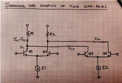
In an effort to see this for myself, I drew (noodled!) this diagram: 


There are four transistors -- two differential pairs with RF coming into the bases of the pairs. 
The LO is a square wave.  The LO alternately turns on transistors 1 and 4, then 2 and 3.  When 1 and 4 are on, we are in period 1 -- here there is no switching of polarity.  Portions of the RF waveform are passed to the outputs.  But when the LO turns on transistors 2 and 3, portions of the RF wave form are "crossed over" to the opposite output.  Polarity is reversed.  We see this in period number 2. 

Take a look at the resulting output waveforms.  This is the same waveform we see coming out of a diode ring mixer.  I really like this drawing because in that complex waveform you can actually see the sum and difference frequencies: 


I could see this diode ring waveform myself on my oscilloscope: 


TASK 2 -- Balancing Out the RF Input 

In a diode ring, and in other diode mixers, the balancing out of the input signals really takes place in the trifilar toroidal coils that are part of the circuit.  Barrie Gilbert needed an integrated circuit mixer that did not use coils.  


Again referring to the above diagram, Steve Long of the University of California put it this way: 

The ideal balanced structure above cancels any output at the RF input frequency since it will average to zero.

To fully understand this I find it helps to look at the Gilbert cell circuit drawn in a different way.  Here is a drawing from Alan Wolke W2AEW that I found very helpful. It comes from his excellent YouTube video: https://www.youtube.com/watch?v=7nmmb0pqTU0


Suppose the RF waveform at I1 is causing the current through R1 and R2 to increase.  At the same time, the opposite phase current through I2 will be causing the current through R1 and R2 to DECREASE.  So there is no net effect of the RF signal at the output.  The RF is balanced out. 

TASK 3 - Balancing Out the Local Oscillator Signal 


Here too I used my own drawing, and was guided by the words of Steve Long: 

It also cancels out any LO frequency component since we are taking the IF output as a differential signal and the LO shows up as common mode.  

The important thing to realize here is which transistors are being turned on and off by the local oscillator signal.  On one half cycle of the LO, transistors 1 and 4 are on.  So  the LO signal at the LO frequency are both pulling the same amount of LO frequency current through the resistors. So you have the same change in voltage at the output terminals.  And the output terminals are differential.  The LO signal results in no voltage difference between the terminals.  So the LO frequency is balanced out. 

The same thing happens on the following half of the LO cycle.  Here, transistors 2 and 3 are turned on. Again, both transistors pull the same amount of LO frequency current through the resistors. There is no differential voltage.  So no LO frequency energy passes to the output.  LO frequency is balanced out. 

--------------------------------

I am surrounded by Gilbert Cell Mixers and I have been using them in my homebrew rigs for many years. I use them in up-converters for my RTL-SDR receivers.  I have one in the downconverter for my 17 meter receiver and had one as the mixer in my first SSB transmitter. I built a 40 meter SSB transceiver with NE602s on either end of the crystal filter. Years ago, I built a DSB transceiver with several NE602s.  My SST QRP CW transceiver is made with NE602s. I have on my bookshelf Rutledge's book "The Electronics of Radio" that is all about the NORCAL 40 transceiver, built using NE602 chips.  But until now I really didn't know how these chips worked.  Truth be told, for me they were mysterious little black boxes, and that bothered me.  Now I feel a lot better about using these clever devices.  I plan on stocking up on the old style (non-SMD) NE602s.  

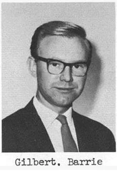
Apparently Barrie Gilbert rejected the idea that he invented the circuit that bears his name.  It seems that Howard Jones first used this circuit in 1963, with Gilbert developing it independently (in an improved form) in 1967. 

 Barrie Gilbert was quite a guy, with electronic roots in the world of tinkering: 


Designer: Douglas Bowman | Dimodifikasi oleh Abdul Munir Original Posting Rounders 3 Column