Podcasting since August 2005! Listen to our latest podcast here:

Podcasting since August 2005! Listen to Latest SolderSmoke

Monday, January 20, 2025

SolderSmoke Direct Conversion Receiver Project: The Input to the Mixer from the VFO -- How Much Is Enough?


I was asked to post some pictures of how the input from the VFO (from the J-310) to the diode ring mixer looks.  The picture above is the VFO output across a 47 ohm resistor to ground through the .1 uf cap to the drain of the J-310.  The mixer is NOT connected.   The question is: Is this enough VFO signal?   

Realize that the VFO is just turning the diodes on and off at the VFO rate.  See this page for more details: 
Look carefully at the scope pattern and at the diagram.  Also look at Alan Wolke W2AEW's excellent video (URL in the above post).  You will see the importance of the VFO turning on and off the diodes.  This is how the diode ring multiplies by 1 and -1.  This is how mixing happens.  This is how audio is produced.  

Now, back to the question:  Is the output we see above "enough."   We can check to see if the VFO is turning on and off the diodes by reconnecting the mixer to the VFO and looking again at the mixer's VFO input port (with no resistor connected).  This is what I see when I do this: 


Here you can see the diodes being switched on and off on the peaks of the VFO voltage.  That is the flat topping you see.  It looks to me as if this is enough. And indeed I have no problem hearing down to the band noise (I can hear an increase in the hiss when I connect the antenna) and I can hear plenty of CW, FT-8 and LSB signals.  I am using ordinary 1N4148 silicon diodes.  

Often we hear manufacturers say that their mixer (like the SBL-1) needs 7 dbm (about 1.4519 V peak to peak across 50 ohms) input from the VFO.  But I think that is just for the SBL-1.  Ours is a homebrew diode ring.  It is, I think, different. So it might not NEED 7 dbm.  In fact, look at the voltage level differences:  Across the 50 ohm resistor we see 504 mV p-p.  But with the diode ring connected we see 1.5 V p-p.  This implies that the LO port input impedance is not 50 ohm, but is probably around 150 ohms.  Indeed when I put a 150 ohm resistor across the output of the VFO (no mixer connected) I measured aroung 1.4 V p-p 

Bottom line:  Just make sure your VFO is turning the diodes on and off. 

Saturday, January 18, 2025

Looking for Contacts on 10 meter AM from the Dominican Republic -- 29.005 MHz AM


I was listening to the Old Military Radio Net this morning and I heard Tim WA1HLR talking about some contacts that he had made on 10 meters, near 29 MHz.  So I pulled my modified CB rig off the shelf, connected a power supply and my 10 meter vertical, and began to listen.  Soon I heard CQs!  One from G4ITR and then one from  G4VZR.  I now have high hopes for at least one QSO.  So please, point those ten meter beams at the Dominican Republic and give me a call.  I am on 29.005 Mhz.  

73  Bill HI7/N2CQR

Wednesday, January 15, 2025

Ugly and Manhattan Construction from Popcorn Electronics


Todd (oops, I mean Vasily) has a really nice video on Ugly and Manhattan construction techniques on his re-born Popcorn Electronics site.  See above for the video.  The site's URL is https://qrp-popcorn.blogspot.com/

Some people apparently dislike these techniques.  To each his own, but I like the Manhattan method.  In fact, in the SolderSmoke Direct Conversion project, we are recommending the use of Manhattan circuit board tecniques.  With Manhattan, you get a lot flexibility.  At one  point, for example, the High School students told us that they had forgotten to put a needed pad on the board.  No problem!  Just glue in a new one.  Or if you put in one too many, just take one off.  

You also keep all the circuitry and all the connections on one side of the board.  This facilitates repair or modification.  This kind of thing is not so easy when you have components on one side of the board and the connections on the other side.  You spend a lot of time flipping boards over, breaking wires,  trying to remember what goes where.  Also, because the pads push the connections a couple of millimeters above the ground plane, I find that Manhattan technique actually reduces the chances for an accidental short to ground. 

There has been some discussion of where the term "Manhattan style" comes from.  Having been born on Manhattan island, I too wonder about the origin of the term.  Some see it as the result of the grid pattern (like Manhatten's street grid) that results from the rectangular or square pads that are often used.  Others point to the vertical parts placement that we see when looking at a board from the side -- the parts look like the skyline of Manhattan.   Either explanation, I think, works.  

Here is a Manhattan-style board I recently built in the Dominican Republic for my homebrew 15-10 meter SSB transceiver. I couldn't find any Gorilla glue here, so I went with Loctite Coqui. Same stuff.   Latin American super glue! 

The 10 meter Beacon at HI7/N2CQR (and reception reports)

Above is the 10 Meter beacon at HI7/N2CQR.

The first one to hear the beacon was Dean KK4DAS in Northern Virginia, within hours of it going on the air. Here is Dean's recording of what he saw and heard:

Later, Mike WN2A heard it. Pete N6QW in California may have heard it too. A number of stations are reporting reception via the Reverse Beacon Network (RBN): It is being picked up almost daily (gray-line?) by Rico DF2CK who has an amazing station in Germany. K1RA in Warrenton Virginia (also an amazing receive set-up) is also picking up the station. W3OA in North Carolina is also hearing it and reporting by RBN. TI7W in Costa Rica has also heard it. Sadly, RBN is kind of clunky with beacons -- it seems to obstinately insist that I am in Northern Virginia.

Rico DF2CK writes:

Hi Bill,

thanks for info. 3 Watt can be loud on 10 if condx are good :)

The west direction skimmer setup on 10 m is a 6 el Yagi into a SDR with
AD9255 adc and XC7Z020 fpga.
A design by Pavel Demin which I am testing for a while now.

Enjoy the Caribean, here its minus 2 C and boot high snow.

73, Rico
DF2CK

Check out Rico's amazing station here: http://df2ck.de/

Andy K1RA wrote from Warrenton (Northern Virginia): 

Hi Bill
  Cool on spotting your beacon.  With good conditions I'm surprised you're not being heard elsewhere.

  I'm running a multi-band, multi-mode skimmer for CW, FT8, FT4, WSPR & JS8CALL continuously and simultaneously covering 160m-6m, 24x7 with Redpitaya SDRs and KiwiSDR/RaspSDRs


15 minute map view through PSKreporter here:


73 & good DX'ing!

andyz - K1RA

Tuesday, January 14, 2025

Shock and Awe: The Story of Electricity --- Wonderful Video by Jim Al-Khalili (sent to us by Ashish N6ASD)

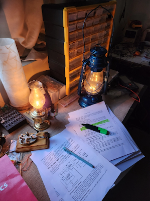
From Ashish N6ASD -- Oil Lamps and Electronics

Here is the link to the video: 


First, thanks to Ashish Derhwagen N6ASD for alerting me to this video.  You should all check out his blog. 

This is a really important video.  It is the best I have seen about the history of electricity and electronics.  It is from 2011, but it is still very good. Jim Al-Khalili travels through the world and displays the actual devices developed by the likes of Heinrick Herz,  Guglielmo Marconi, and Jagadish Chandra Bose.  There is great discussion of Benjamin Franklin, Volta and Galvani.  The role of electricity in The Enlightment is discussed.
  

Jim talks about the early transatlantic cables, and why some of them didn't work. 

We see Jagadish Chandra Bose developing early point-contact semiconductors (because the iron filings of coherers tended to rust in the humid climate of Calcutta!) 

There is a video of Oliver Lodge making a speech.   There is a flip card video of William Crookes (one of the inventors of the cathode ray tube and the originator of the Crooke's cross).  

We see actual coherers.  

There is simply too much in this video for me to adequately summarize here.  Watch the series.  Watch it in chunks if you must.  But watch it.  It is really great.  

Thanks Ashish.  And thanks to Jim Al-Khalili.  

https://www.youtube.com/watch?v=Gtp51eZkwoI