Just go to http://soldersmoke.com. On that archive page, just click on the blue hyperlinks and your audio player should play that episode.
http://soldersmoke.com
Thanks to Peter Parker VK3YE for alerting us to this beautiful receiver from Bore 4O6Z in Montenegro. This may be our first ever report on a Montenegrin rig. And it is a thing of beauty. Bore says it is based on a phasing circuit by homebrew legend V. Polyakov, RA3AAA.
It is snowing here today, so I am stuck in the hamshack. YEA!
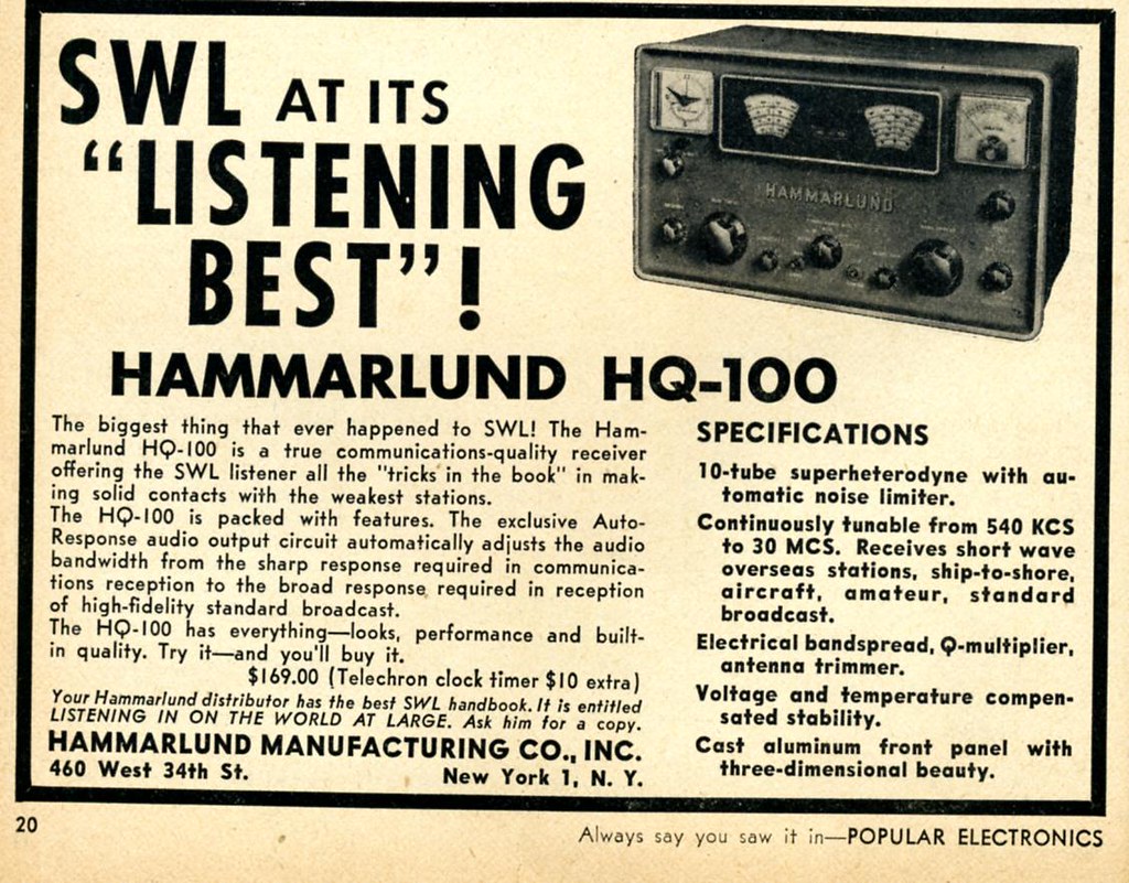
I've had the Hammarlund HQ-100 receiver on the bench because I am building an outboard digital frequency readout for it and for the DX-100. More on this later. But as long as I had it on the bench I decided to do a mod to the audio output that has LONG been needed.
Here is a nice web page that describes the problem and the solution. The problem is the "Auto Response audio output circuit" touted in the add up above. Essentially I had to remove the touted circuitry. The AutoResponseectomy only took me about 15 minutes and the results are quite noticeable. The old receiver sounds a lot nicer. I'm listening to 40 meter AM now. FB.
I listened to it as I aligned my HQ-100 receiver and worked on a digital frequency readout for the old receiver. The interview was the perfect accompaniment for such a project. Inspirational stuff. Lots of great info on QRPp and homebrewing. Mike talks about some of his more famous rigs including the voice-powered New England Code Talker (pictured above).
I loved the story of Michael carting his DX-100 home in a wagon. And I really sympathized when he described the harsh reaction of the phone operator to his early efforts at voice modulation.
Strongly recommended! You won't be disappointed. Great interview. Thanks to Eric and Mike.
Hi Bill I thought I would drop you a quick line to show you something I have been playing around with for the past couple of weeks. It's a SSB superhet using a PJRC Teensy 3.1 microcontroller (YouTube link below), and a great audio library by Paul Stroffregen. Suffice to say I'm really happy with it.
There is a direct conversion front end, albeit using a VFO 15kHz down from the incoming RF. The 15kHz IF is then fed into the Teensy audio line in which can handle up to 22kHz. From there everything is in software. First is a 2.4kHz BPF tuned to the LSB, followed by mixer with a 15kHz BFO. Finally, there is a 2.4kHz LPF. Next step is to add both CW-wide and CW-narrow filters which can be selected during run time.
As you can tell from the video, my antenna is not the best and I have quite a bit of QRM in the shack. I really need to think about a better antenna, but that's another story.
I have been following your R2 endeavors with interest, and as I said to Pete I will attempt to replicate the R2 on a Teensy. I will try and use the divide by 2 arrangement you tried as the logic looks right.
I will also be adding in a transmitter. For that I'll use the microphone input and then take the audio from the line out straight to the RF pre/power amp.
I must admit that I really enjoy homebrewing hardware/software hybrids as you get the best of both worlds. As i say that, I wonder how much ADCs cost these days to directly digitize RF... Now that would be interesting.
I'll say again that I really enjoy following the podcast. I have loved electronics since I was a small boy when my parents bought me a battery, switch and light bulb. This age of cheap DDSs, microcontrollers and the like is amazing, and I get so much enjoyment putting them all together to make functioning ham radios. I hope more get into the homebrew field as the entry barrier is dropping fast.
Feb 10 at 7:40 AM Hi Bill and Pete, My work is closed today due to the snow so I wanted to show you what I've been up to. I built sort of a test fixture a while back for those cheapie EBay AD9850 boards based on AD7C's DDS circuit using an Arduino Uno as a controller. Last summer someone posted a link to Analog Devices App note AN-423 on QRP-Tech I think. It was always on my list of things to try. Armed with a schematic of the eBay DDS gleaned from Doug Pongrance's website, I got to work. It involved cutting a trace or two on the DDS board using an X-Acto knife. Two outputs of the DDS chip are fed into a wideband transformer as in the app note's second page and I hung a scope probe off the secondary of the transformer. Basically you are removing the Rset resistor on the DDS board (marked R6 on mine) and using a 2N7000 MOSFET as an electronic version variable resistor and modulating the MOSFET. This lead to much frustration over the afternoon. No output on the scope!! Did I make an error or connect something up wrong? I was using the 600 ohm output of my HP652A audio generator. I thought about it during lunch and decided to try the 50 ohm output. Bingo!! At the 3V RMS range setting on the generator I now have some kind of signal. Not a nice sine wave shaped AM output but at least something resembling a clipped sine wave. The circuit is really touchy as far as needing a hefty audio signal in. The output of my iPhone at max volume doesn't turn on the DDS chip. I set the DDS for 1200 kHz and can listen to it on a Radio Shack portable radio. Varying the audio generator varies the received tone on the radio just like I was expecting. I just need to figure out what's up with the audio levels. Chris KD4PBJ
Feb 11 at 7:53 AM
I did manage to reduce the audio a little and get clipping to go away. I'll send another set of oscilloscope shots tonight.
The only thing I don't get is why the audio level needs to be so high. The app note said 1 V peak to peak should be enough but I am having to drive it with 7 V p-p audio to get a decent waveform with 0.8 V p-p RF.
I did cut the traces going to pins 12,20 and 21 to the DDS chip rather than pick up the signals elsewhere in the board. This was because once the traces go into vias down in the board, I'm not sure what else they connect to.
Chris
Feb 11 at 1243 PM
Found the original email from May of last year about the app note. It was on the EMRFD list. After hearing you guys lately talking about AM it has me excited about an AM transmitter.
I just got a thought over lunch that I'm going to try tonight and that is biasing the 2N7000 gate with a couple of volts to see if I can get the transistor on. Then maybe I don't need as much audio. I'll definitely put a series cap in though to my audio source so I don't fry my iPhone!!!
More to come this evening!
Chris
Feb 11 11:23 PM
I'm so excited!!
That's exactly what I needed to do-bias the gate of that 2N7000 so I'm not depending on the audio to turn it on, only to modulate it.
I hooked up a 9v battery across a 10 k trim pot and connected the wiper to the gate of the fet. A 10 uF cap is in series with my audio line as not to feed DC back into my source.
I have audio and now the output of a small radio or iPhone modulates it fine.
So this is a great proof of concept! Those cheapie DDS modules from China can be AM modulated.
I need a mic amp now, filter (surgery to the board disabled the on board LPF, but yes Steve I'll install one right away), buffer amp and some kind of linear RF amp to get a few watts.
Wow, you really have to spend 20 minutes and watch the video (above). It is really well done. I loved it. I give it FIVE SOLDERING IRONS!
And big news today! They did it! Gravitational waves finally detected. Here is a good New York Times article that includes a recording of the signal, a nice NYT video that has a good explanation (with phasing!) of how lasers are used in the massive detectors, and mention of Joe Taylor, K1JT, whose Nobel Prize winning work contributed to this great discovery.
Even I, with my luddite tendencies and analog preferences, have recently bumped up against the speed limit of 74 series logic chips. The Si5351 chip in the I and Q VFO for my phasing receiver will run up to 160 MHz. But the 74 series inverters and flip flops that I have attached to the output don't seem to want to go beyond about 120 MHz. Our old friend Thomas LA3PNA tells us how to break this speed limit: http://www.potatosemi.com/
Be sure to go their "Milestones of 74 Series Logic" Page. I like their explanation of the brand name:
Back on 2 February I was on 160 AM with the DX-100, talking to WA4PGI. At the end of our QSO we got a call from a station. I was at first confused -- was this station calling on SSB? Or was he calling on AM? Turns out that he was -- in a way -- on BOTH. K4DBK was -- I think -- running an old Collins KWS-1, the transmit side of the famous Gold Dust Twins. Aptly named: It was built in 1955. 1000 watts output. $2095.00 in 1955. Gold dust indeed.
The really interesting thing about this rig was that it put out CW, SSB and SSB plus the carrier. I think that was what we were hearing from K4DBK. FB.
Does anyone have an e-mail address for K4DBK? I'd like to drop him a line.
Thanks for all the comments and advice. I have come to understand the wisdom of divide by 4 IQ circuits. Fortunately it was very easy to convert the divide by two 74AC74 circuit described earlier to a version of the divide by 4 scheme seen above. (From the SDR Ensemble II Receiver: http://www.wb5rvz.com/sdr/ensemble_rx_ii_vhf/04_div.htm) This change provided a great way to observe 1) the improvement in the output signals from the VFO and 2) the resulting improvement in receiver performance, especially opposite sideband rejection. Here are some numbers. I was very pleased to discover that my Rigol scope will measure duty cycle and phase difference. Thanks Rigol! AD9850 Divide by 4 : 7.212 MHz Duty cycle: 48.3 Phase Difference: 87-90 degrees Si5351 Divide by 2: 7.212 MHz Duty Cycle 49.6 Phase Difference: 83 degrees Si5351 Divide by 4 7.212 MHz Duty cycle 49 Phase Difference: 85-90 degrees Additional improvement came when I switched the power supply to the IQ inverters and Flip Flops. I switched from 3.3 to 5 volts: Si5351 Divide by 4 7.105 MHz Duty Cycle 49.7 Phase Difference: 90 degrees When I took the VFO box and put it back in the receiver with the divide by 4 scheme and the 5 volt supply I immediately noticed a big difference in performance. It was obvious that opposite sideband rejection was back to what I had had with the AD9850, perhaps better. I have a quick and dirty method of measuring opposite sideband rejection: I put an RF signal into the antenna connector. I put the 'scope on the audio output. I tune (on the desired sideband) for 1kHz audio and I measure the output voltage. Then, with the audio gain and RF sig gen output in the same positions, I tune to the opposite sideband, again tuning for 1 kHz, again measuring audio output. With the divide by 4 scheme and the 5 volt supply, the opposite sideband was so weak I had trouble measuring it. I estimate the rejection to be at least 32 db -- this is back in the range of what I had with the AD9850, and significantly better than I had with the divide by 2 scheme.
Now I just need to figure out how to get the Si5351 VFO sketch to tune above 42.94 MHz. For some reason it quits at this point, switching down to 2 kHz output, and keeping me on 30 meters and below. Thanks again to Todd VE7BPO for a lot of help with the hardware and to Tom AK2B for help with the Arduino code.
Fresh from a great success with the use of the M0XPD divide by 4 I and Q VFO in my Frankenstein Phasing Receiver, I got ambitious. And greedy. I wanted more. More frequency coverage. More bands. Divide by 4 can really limit your frequency range. The AD9850 only goes up to 40 MHz. Divide by 4 and you can't even get the 30 meter band. So I started looking at other options. Si570 looked nice, but here the lower limit was the problem: 10 MHz. Even with divide by 4, that knocks out 160 meters, a band I am very interested in lately, and that seems to sound especially good in a direct conversion receiver. Once again, the controversial Si5351 was calling my name. It would go down to 8 kHz and up to 160 Mhz. Woo Hoo! If I could build a divide by 2 IQ VFO, I could cover 160-6 meters. Here is the basic idea. From: http://www.markimicrowave.com/blog/2015/04/top-7-ways-to-create-a-quadrature-90-phase-shift/
The Flip Flops are set up to change state when the input signal is going up. By putting an inverter at the input of the bottom FF input, in effect you have that one changing state when the input signal is going down. Look at this for a minute or so. Look at the square waves at the bottom. See it? See how it takes an ordinary signal and spits out two signals, one 90 degrees off the other? Pretty cool, don't you think?
With lots of hardware help from Todd VE7BPO, and software help from Tom AK2B (wizards both), I got my Si5351 divide by 2 circuit working today. You can see the resulting I and Q in the picture at the top. But I am discovering that there may have been wisdom behind those divide by 4 circuits. My opposite sideband suppression isn't as good with this /2 scheme as it was with the AD9850 divide by 4. I'm still trying to figure out why. I may have to go back to divide by 4. Stay tuned.
Dear Friends, The UJT transmitter circuit was improved considerably today. The power output has increased to 1.48mW and the start-up "whoosh" is now far less objectionable. It's currently running in beacon-mode at 3687.8kHz. I'll resume "CQing" as soon as I've returned from an hour's walk in the woods. I hoping to work K1QO among others. 73, Mike Added five QSOs today. Seabury/AA1MY is in Maine...exactly 100 miles from my doorstep. It's wild to think that we made a one-hundred mile radio contact on a unijunction.
This is a really amazing presentation on our beloved BITX rigs. This presentation takes the viewer from block diagram to schematic to photos of the actual circuits and throws in great graphics showing spectra and filter curves etc. There is no sound. Here is the link in case the embed above doesn't work: https://prezi.com/yn2loy4mi0wo/bitx20/ Thanks Chris!
AA1TJ writes: I spent most of a week working to raise the RF output power from my unijunction transmitter to nearly 1mW. I was rewarded this evening with two contacts.
Jim/W1PID exchanged (599/449) signal reports with me from Sanbornton, NH (112km) at 2210z!
Dave/K1SWL did the same (589/229) from Newport, NH (95km) some four minutes later!
I should think these were the first-ever radio contacts made using a unijunction transistor as the transmitter.
FYI: my receiver was comprised of a single 1N34a germanium diode mixer followed by a single 2N35 germanium transistor audio amplifier. Great signals on this end.
I've wanted to change the VFO in my R2 phasing receiver. The AD9850 DDS VFO with a divide by 4 I-Q generator limited me to 160, 80 and 40 meters. But an Si5351 chip will go up to 160 MHz. With a divide by 2 I-Q generator, this should allow me to cover 160 through 6 meters. I got the Arduino, LCD and rotary encoder all working tonight. Thanks to Thomas LA3PNA for the code, and to Tom AK2B for help with the Arduino. The Si5351 board that you see sitting atop the Arduino is the work of Dean AC9JQ. Thanks Dean.
The flip-flop and inverter IC's should arrive this week. That will allow me to finish up this VFO conversion project.
Daniel HK4DEI wrote to report that page 149 of the SolderSmoke book was providing some solace and comfort as he struggled to get his version of Peter Parker's Micro 40 Double Sideband rig going. He was having problems with the amplifier. He was almost at the point of sacrificing chickens to Papa Legba. I wished him luck and told him to hang in there.
Elisa saw my e-mail to Daniel and complained that I hadn't given him the solution to his amplifier woes. I tried to explain to her that there are sometimes things in this universe that are just UNKNOWABLE. C.F. Rockey W9SCH (who alerted us in SPRAT 22 to the chicken sacrifice option) spoke of transistors that exhibit "quantum mechanical necromancy." Rockey explained that when this happens, "The transistor simply turns up its toes and dies. Not even an Atomic Physicist can tell you why!"
But Daniel persisted. And he won the battle:
Hey Bill
Did you kill some chickens already? If you did, THANK YOU! If you don't, then please enjoy a nice sancocho de gallina for me.
But seriously... guess what?
FAKE TRANSISTORS!!!!
I knew I couldn't be screwing everything up so badly and VK3YE's circuit couldn't be so wrong.
I was getting nuts trying to understand why it wasn't working, changing a single inductor could fry the final instantly or not getting any power out at all (?) also my final BD139 was getting extremely hot, and many of them died with no apparent reason (Page 149!!!!).
I ordered a "good" deal of BD139's and BD140's combo for an incredible low price from [A WEB SITE], I've ordered many *apparently good components from that site with no problems so far... mainly resistors and capacitors. Having tried everything to get my circuit working and after some quick online search about fake transistors from china my suspicions grew considerably and I remembered some -other- BD139's I had ordered from Amazon some time ago.
I proceeded to solder the new transistors in place in my PA and Bingo! No more heating of the final and about the expected 0.5W out from my first DSB homebrew rig. I quickly reported to a fellow homebrewer in a local net and the report was amazing! 59 +10, the final transistor was comfortably warm to the touch and my mind could finally rest... lesson learned! What an electromagnetic achievement!
Just wanted to share my success Bill and thank you again for you book and you kind response.
Please say hi to Elisa and the Cristalinhos from a fellow Latin friend.
Michael updates Peter (and us!) us on his efforts of this week:
Grüss Peter!
Thanks for the nice message. Yes, I knew that you were going to be QRV with your ZnO transceiver but I never heard if you had made any contacts. I guessed that you had not, otherwise I'm sure you would have let me know.
Again, I think your circuit looks really great! It's amazing to think you managed to squeeze 500uW from a scrap of oxidized zinc-plated steel. Even if you didn't make a contact, what you are doing is really fantastic. Congratulations on the creation of this amazing radio!
Okay, so I spent most of the afternoon at the workbench. Thus far I'm only using a single SRD (step-recovery-diode...1N5401 rectifier). Of course the result is a unipolar pulse. The idea did work as planned, however the power only increased by 2.24dB. The maximum RF output power is now 230uW. At least the SRD makes a pretty pulse :-)
Please find two scope captures attached to this message. The first (0002) shows the SRD generated unipolar pulse. As you can see, the pulse width is nearly perfect for the job. The second trace shows the output RF waveform. The worst spurious energy is ~20dBc. The second image shows the 507kHz waveform at the unijunction emitter along with the output RF waveform.
The beacon is presently off the air, but I look forward to trying my luck tomorrow with a back-to-back pair of SRDs. A bipolar pulse pair will provide a shock impulse once every 3.5 cycles, instead of once every 7 cycles with the present unipolar drive pulse. The bipolar pulse pair should result in increased RF output power as well as a slight spectral improvement.
It's only a matter of time before you make a ZnO QSO, Peter. As we always say, the difficulty merely sweetens the eventual success.
A broadband measurement of my output power (using an AD8307 log-amp power meter) indicates 139uW. Spurious frequency energy accounts for 2uW, leaving 137uW at 3.552MHz. I believe this is roughly the output power produced by your ZnO transmitter?
This morning I'll attempt to increase the unijunction (UJT) 80m RF output power by inserting a pair of back-to-back standard-recovery power supply rectifiers (1N5401-ish) at the UJT base-2 to ground node. Thus far I have relied exclusively on internal UJT nonlinearity for the generation of harmonic energy. I've reason to believe the minority carrier charge-storage capability (normally a defect, but hopefully a virtue here!) of these rectifiers will efficiently produce a bipolar pulse-pair every 1/500kHz seconds resulting in an odd-order comb-spectrum. At least that's the plan...we'll see how it works out ;-)
Peter, I never heard the results of your ZnO DXpedition? Any luck OM?
Okay, I'm off to the Hobbit-Hole. My heartfelt thanks to you all for your shared interest in this cock-eyed project.
73,
Mike, AA1TJ
Peter, DL3PB, in Germany respond with amazing news of his own. Peter is homebrewing his own tunnel diodes, using Zinc Negative Resistance Oscillators. No store-bought appliances for him!
At this point you really have to visit the pages of Nyle K7NS
Nyle tells of building a little microwatt transmitter, and, once the snow melted, climbing a hill 5 miles from town to see if he could hear it. This reminded me of young Marconi's early efforts in Bologna.
Peter writes:
Hi Folks,
Mike, your plan on how to increase output-power sounds reasonable – yes, a few dB could really help, to make reception a bit steadier and thus allow a QSO.
Well, I thought we had already talked about the ZnO TRX attempt, but obviously we didn’t. The reason is dead simple - It didn’t work.
[ The ZnO TRX is a minimalist 80m band transceiver with a homemade tunnel-detector-diode as the only active device – based on Nyle’s K7NS experimentshttp://sparkbangbuzz.com/zinc-osc-2/zinc-osc3.htm – please find attached an early schematic ]
Three days in a row after Xmas I tried for several hours each, I had announced the activity on QRPSPOTS and the German QRP Forum. Thus several guys within the right distance were really trying hard to copy. I used different temporary antennas, mostly verticals, but also a sloper dipole - nada, niente , nothing. One or two OMs reported weak CW signals on the scheduled QRG, but too deep in the noise, to even make out, whether it was me or someone else.
Yes, power is more or less comparable, actually it’s 0.5mW +/-3dB depending on the day’s form of the homemade tunnel-detector, but I guess all my antennas are some dB behind a full-size dipole, so at the end it’s pretty much the same.
Folks were very cooperative during the test itself, but after it was clear, that it had not worked, the usual trolls showed up to explain, why that never could have worked... I plan another test within the coming week e.g. during the PA-contest next weekend ( I’m only 30km from the dutch border ) with a base loaded 15m vertical – be assured, you’re the first to hear about any success in terms of QSO or just being heard anywhere.
What would we go for, if everything works as expected and/or right from the beginning – or as Jim said it : What fun...
73!
Peter/DL3PB
Finally, Alan Wolke provides a very illuminating (as always) explanation of tunnel diodes):
AA1TJ reports: Breaking news from W1PID... "Mike! I just copied the beacon. I got 'VVV de AA1TJ 150 uw' and it faded out. 2146Z on 3551.95MHz" That's it! Jim copied a message produced by a lowly unijunction at a distance of 112km. How's that for cool!In a nutshell... the unijunction runs as an R-C relaxation oscillator at ~500kHz. A quartz crystal at the emitter frequency-locks the sawtooth waveform to 507kHz. The 7th harmonic is admitted to the antenna via a bandpass filter. The RF output to DC input conversion efficiency is all of 0.1%. Heat-sink? Check! Mission statement: "...to boldly go where no unijunction has gone before." Cheers, Mike, AA1TJ I think the really cool thing is that EM waves are once again flying out of the Vermont Hobbit Hole, propelled into space by the poet laureate of QRP.
QST de AA1TJ... I've a 150uW transmitter built from a single unijunction transistor currently running as a beacon on 3552kHz. If my New England amateur radio pals would be so kind as take a listen for it I'd be most appreciative!
We are honored to induct Alan Wolke W2AEW into the Colorburst Liberation Army. And for his valiant effort to build and explain a MMM Low-Pass filter, he is immediately promoted to the rank of CBLA Two Star General. Congratulations General Wolke. As is the case with all of his videos, this one has already had an impact far and wide. Ian writes from far-off Western Australia:
Jan 27 at 6:19 PM
G'day Bill,Just in case none of your other correspondents have brought it to your attention, here is a great video W2AEW has put up showing really clearly the positive effect of a low pass filter on the output of the Michigan Mighty-Mite.
It made me appreciate the benefits of an LPF more fully. It's always been clear to me that the harmonics would get rolled off, but in my head I hadn't made the connection between that and the improvement to the beautiful smooth sine wave that we are working towards.
Anyway, I thought you, and your mate Steve "Snort Rosin" Smith may be interested.
Thanks to you and Pete for Soldersmoke, I'm sure you're responsible for keeping the flame alight in many a ham.
73,Ian VK6MIB
And Steve "Snort Rosin" Smith, the guru of low pass filters, observes:
Of course, to work properly in the land down under, the inductors must be wound in the opposite direction as those in the Northern Hemisphere :-P .
Seriously, there is a lot to be learned from the lowly Mighty Mite especially regarding impedance matching; not to mention LC circuits, link coupling, amplifiers, oscillators, etc. . What fun!
Sometimes the Radio Gods conspire against you. Check out the chart above. It shows relative humidity at my location. I zapped my LCD display right around 2000 UTC on January 25, 2016. That poor little LCD didn't stand a chance :-( Right now relative humidity here is 79%. No sparks now! I like the solution (!) proposed by Brendan, EI6IZ: You can get an anti-static spray designed to treat carpet, upholstered furniture etc. This is a sensible thing to do if one tinkers with electronics and for the average hamshack a bottle will last for many years as it only needs to be applied lightly and infrequently. For example http://ie.rs-online.com/web/p/esd-safe-clean-room-treatments-lotions-dispensers/0182893/ For cheapskates however, diluted fabric softener sprayed on the carpet and chair will work well for at least a few months but will require much more frequent application than the 'proper stuff'.
I give my car seat an occasional squirt in dry summers to stop the 'zap' when getting out on a dry day.
"SolderSmoke -- Global Adventures in Wireless Electronics" is now available as an e-book for Amazon's Kindle.
Here's the site:
http://www.amazon.com/dp/B004V9FIVW
May 11, 2024. Basically, I am really pissed off!
-
Being Italian, it does not take too much to get up my ire! Yesterday on my
phone showed up a link to a hackaday posting. It was a wonderful sharing
about ...
Extreme geomagnetic storm effect on 10m
-
Although I follow space weather with some interest it's rare to see it
reported in the general news. Recently I repaired my 10m band dipole which
had been ...
ReturnLoss of UHF series adapters
-
This article reports a simple but robust measurement of the ReturnLoss of a
pair of UHF adapters from 1 to 501MHz. Load selection To measure ReturnLoss
of ...
Solar Noise on the 28 MHz band - 10th May 2024
-
*10th May 2024:* I had the radio turned on in the background this morning
and I noticed a large burst of noise from the sun. I had the SpectrumLab
softwa...
An Inline RF Step Attenuator for QRPp Work
-
I don’t need to explain the attraction of low power operation; if you’re
reading this, the chances are that you are already a convert. I’ve been
operating ...
A 51S-1 Restoration Story
-
I came across my Collins 51S-1 in a big junkyard in Ankara, Turkey around
2012. It was in a pile with a lot of other electronic scrap, probably from
one o...
New QRP Cluster Online From OM0ET and OM6APN
-
By DX EXPLORER
DX EXPLORER
Paul OM0ET and Peter OM6APN recently launched a new cluster dedicated to
QRP operations. Have a look and I hope you will enjoy...
3D Printing The Hadley 114mm Newtonian Telescope
-
Yes, we’re building a 3D Printed Newtonian Telescope called Hadley. It’s
being printed in PETG and in the video below, I give a quick tour. My build
isn’...
3D printed project boxes
-
I have been busy with some other things that have kept me away from
electronics projects for quite a while. Now I can get back to them, but
realize I n...
Daylight Again – An all Analog Radio
-
What’s all this? In 10 seconds, A high performance, 7MHz, 5 watt SSB rig
Draws just 24 mA of current 90 dB dynamic range, 80 dB close-in dynamic
range 3D ...
Adding Enclosure to your sBitx Boards Order
-
The early buyers of the sBitx board set who bought it for $270 USD might
want to also add the enclosure (box) for in the kit. What you will now get
is a f...
Digi-chirp! Digital synthesis of ‘nostalgic’ CW
-
The bottom ends of 80, 40 and 20m are not what they used to be. For
starters, the busiest part is the digital segment where computers talk to
computers – l...
-
A Simple Speech Processor
(For QRP/SSB Homebrew Transceivers )
Over the last few weeks I had been thinking to build a small AF speech
processor to add to...
A New Look for your uBitx!
-
Adding a "Cool Blue" Display to your uBitx!
The standard "green background" with black lettering frequently reminds me
that I suffer from Chronic seasickn...