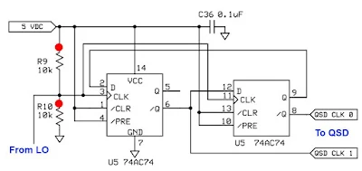
Thanks for all the comments and advice. I have come to understand the wisdom of divide by 4 IQ circuits.
Fortunately it was very easy to convert the divide by two 74AC74 circuit described earlier to a version of the divide by 4 scheme seen above. (From the SDR Ensemble II Receiver: http://www.wb5rvz.com/sdr/ensemble_rx_ii_vhf/04_div.htm)
This change provided a great way to observe 1) the improvement in the output signals from the VFO and 2) the resulting improvement in receiver performance, especially opposite sideband rejection.
Here are some numbers. I was very pleased to discover that my Rigol scope will measure duty cycle and phase difference. Thanks Rigol!
AD9850 Divide by 4 : 7.212 MHz Duty cycle: 48.3 Phase Difference: 87-90 degrees
Si5351 Divide by 2: 7.212 MHz Duty Cycle 49.6 Phase Difference: 83 degrees
Si5351 Divide by 4 7.212 MHz Duty cycle 49 Phase Difference: 85-90 degrees
Additional improvement came when I switched the power supply to the IQ inverters and Flip Flops. I switched from 3.3 to 5 volts:
Si5351 Divide by 4 7.105 MHz Duty Cycle 49.7 Phase Difference: 90 degrees
When I took the VFO box and put it back in the receiver with the divide by 4 scheme and the 5 volt supply I immediately noticed a big difference in performance. It was obvious that opposite sideband rejection was back to what I had had with the AD9850, perhaps better.
I have a quick and dirty method of measuring opposite sideband rejection: I put an RF signal into the antenna connector. I put the 'scope on the audio output. I tune (on the desired sideband) for 1kHz audio and I measure the output voltage. Then, with the audio gain and RF sig gen output in the same positions, I tune to the opposite sideband, again tuning for 1 kHz, again measuring audio output. With the divide by 4 scheme and the 5 volt supply, the opposite sideband was so weak I had trouble measuring it. I estimate the rejection to be at least 32 db -- this is back in the range of what I had with the AD9850, and significantly better than I had with the divide by 2 scheme.
Now I just need to figure out how to get the Si5351 VFO sketch to tune above 42.94 MHz. For some reason it quits at this point, switching down to 2 kHz output, and keeping me on 30 meters and below.
Thanks again to Todd VE7BPO for a lot of help with the hardware and to Tom AK2B for help with the Arduino code.

The problem with your divide by 2 is the extra invertor in one leg. That causes the ratio to vary more from 50/50.
ReplyDeleteOn my UHFSDR, I use a divide by 2, but I have 2 complement outputs from the Si570 which should be very close to 180 degrees apart. A better way with one input is to use 2 EOR gates rather than 1 ivertor. On one put + on the 2nd input, on the other put gnd on the 2nd inputs. This will limit the skew to the difference in propagation delay. That should be very small as both gates are on the same die.
While the Si570 is only specified to go down to 10 MHz, they in face go down to 3.5 MHz. The UHFSDR with the divide by 2 I/Q generator goes down to 1750 KHz and up to 700 MHz.
ReplyDeleteDave -- thanks for your comments. Respectfully,
ReplyDeleteMy limited experiments suggest it's not just the asymmetry added by that inverter on 1 side that wrecks things in the LO/2 version.
As many have stated:
Placing a properly configured XOR stage on each arm for the the 0 and 180 degree signals driving the D-FF clocks did not really improve the LO/2 quadrature output phase error versus frequency significantly.
What works every time: create the 0 and 180 degrees with a D-FF! Of course you are back to LO divide by 4
Generating the 0 and 180 degree signal; with a seperate D-FF and then going into the LO/2 quadrature clock inputs -- or using LO/4 quadrature squared up any input symmetry distortion and resulted in a much greater error-free B/W and also an overall lower phase error when compared to the LO/2 version ---- at least on my bench. I might have committed some illusions of causality due to poor thinking in my bench experiments.
Dave --- does the Si570 make the 0 and inverted ECL outputs internally with a flip flop?
Thanks and best regards,
Todd
The LVPECL drivers in the Si570 produce the 0 and 180 degree outputs.
ReplyDeleteThe LVPECL drivers in the Si570 produce the 0 and 180 degree outputs.
ReplyDelete