Just go to http://soldersmoke.com. On that archive page, just click on the blue hyperlinks and your audio player should play that episode.
http://soldersmoke.com
I've said this before: I just seems so unfair. We just should be able to listen to DSB signals with our beautifully simple homebrew Direct Conversion receivers. I mean, building a DSB transmitter is a natural follow-on to DC receiver construction. And we are using AM shortwave broadcast stations (Radio Marti --I'm looking at you) to test our DC receivers for AM breakthrough. But when we tune these stations in, they sound, well, awful. So unfair! Why? Unfortunately it has to do with laws. Laws of physics and mathematics. Blame Fourier, not me.
Over the years there has been a lot of handwaving about this problem. From Doug DeMaw, for example:
In his "W1FB's Design Notebook," Doug wrote (p 171): "It is important to be aware that two DSSC (DSB) transmitters and two DC receivers in a single communication channel are unsatisfactory. Either one is suitable, however, when used with a station that is equipped for SSB transmissions or reception. The lack of compatibility between two DSSC (DSB) transmitters and two DC receivers results from the transmitter producing both USB and LSB energy while the DC receiver responds to or copies both sidebands at the same time."
That's correct, but for me, that explanation didn't really explain the situation. I mean we listen to AM signals all the time. They produce two sidebands, and our receivers respond to both sidebands, and the results are entirely satisfactory, right? Why can't we do this with our Direct Conversion receivers? I struggled with this question before: https://soldersmoke.blogspot.com/2015/07/peter-parker-reviews-dsb-kit-and.html You can see in that post that I was not quite sure I had the answer completely correct.
It took some discussion with a fellow Vienna Wireless Society member, and some Googling and Noodling for me to figure it out. But I think I've got it:
Imagine a station transmitting a DSB signal at 7100 kHz with a 1 kHz tone at the AF input. There will be signals at 7101 kHz and at 7099 kHz. Assume the carrier is completely suppressed.
We come along with our DC RX and try to tune in the signal.
Remember that they heart of the DC RX is a product detector, a mixer with the VFO (or PTO) running as close as we can get it to the suppressed carrier frequency (which we can't hear).
Lets assume that we can somehow get our VFO or PTO exactly on 7100 kHz. The incoming signals will mix with the VFO/PTO signal. We are looking for audio, so we will focus on the difference results and ignore the sum results of the mixing.
The difference between 7101 and 7000 is 1 kHz. Great! And the difference between 7099 and 7000 is 1 kHz also. Great again, right? We are getting the desired 1 kHz signal out of our product detector, right? So what's the problem?
Here it is: SIDEBAND INVERSION. Factoring in this part of the problem helps us see the cause of the distortion that plagues DSB-DC communication more clearly.
Remember the Hallas Rule: Whenever you subtract the modulated signal FROM the unmodulated signal, the sidebands invert. So, in this case, we are subtracting that 7099 "lower sideband" signal FROM the 7100 VFO/PTO signal. So it will invert. It will become an upper sideband signal at 1 kHz. We will have two identical 1 kHz signals at the output. Perfect right? Not so fast. Not so PERFECT really.
The perfect outcome described above assumes that our VFO/PTO signal is EXACTLY on 7100 kHz. And exactly in phase with the suppressed carrier of the transmitter. But if it is even SLIGHTLY off, you will end up with two different output frequencies, signals that will move in and out of alignment, causing a wobbling kind of rapid fade-in, fade-out distortion. You can HEAR this happening in this video by Peter Parker VK3YE, starting at 6:28:
And you can see it in this LTSpice simulation.
This LTSpice model just shows two diode ring mixers. The transmitter is on the top, the receiver is on the bottom. The transmitter has RF at 7100 kHz at L1 and audio at 1 kHz at R1. The receiver has the VFO at 7100.001 L7, DSB from the transmitter at L12 with audio appearing at R4. It is instructive to watch the output as you move the VFO frequency. If you move the VFO freq away from the transmit carrier osc frequency you will see the distortion. Here is the netlist for the LTSpice simulation:
On paper, using simple mixer arithmetic, you can tell that it will be there. With the VFO/PTO just 1 Hz (that's ONE cycle per second) off, you will end up with outputs at 1.001 kHz and at .999 kHz. Yuck. That won't sound good. These two different frequencies will be moving in and out of alignment -- you will hear them kind of thumping against each other. And that is with a mere deviation of 1 Hz in the VFO/PTO frequency! We are scornful when the SDR guys claim to be able to detect us being "40 Hz off." And before you start wondering if it would be possible to get EXACTLY on frequency and in phase, take a look at the frequency readout on my PTO.
Now consider what would happen if the incoming signal were SSB, lets say just a tone at 7101 kHz. We'd put our VFO at around 7100 kHz and we'd hear the signal just fine. If we were off a bit we'd hear it a bit higher or lower in tone but there would be no second audio frequency coming in to cause distortion. You can hear this in the VK3YE video: When Peter switches to SINGLE Sideband receiver, the DSB signals sound fine. Because he is receiving only one of the sidebands.
The same thing happens when we try to tune in an AM station using a Direct Conversion receiver: Radio Marti sounds awful on my DC RX, but SSB stations sound great.
My Drake 2-B allows another opportunity to explore the problem. I can set the bandwidth at 3.6 kHz on the 2-B, and set the passband so that I will be getting BOTH the upper and the lower sidebands of an AM signal. With the Product Detector and the BFO on, even with the carrier at zero beat AM sounds terrible. It sounds distorted. But -- with the Product Detector and BFO still on -- if I set the 2-B's passband to only allow ONE of the sidebands through, I can zero beat the carrier by ear, and the audio sounds fine.
There are solutions to this problem: If you REALLY want to listen to DSB with a DC receiver, build yourself a synchronous detector that gets the your receivers VFO EXACTLY on frequency and in phase with the transmitter's oscillator. But the synchronizing circuitry will be far more complex than the rest of the DC receiver.
For AM, you could just use a different kind of detector. That will be the subject of an upcoming blog post.
Please let me know if you think I've gotten any of this wrong. I'm not an expert -- I'm just a ham trying to understand the circuitry.
November 4, 2013 Special hour-long interview with Peter Parker, VK3YE -- Early experiences with radio -- CW -- DSB Gear -- Simple gear, and gear that is TOO simple -- VXOs, Super VXOs and Ceramic Resonators -- Building receivers -- Chips vs. Discrete -- Making the leap to SSB -- The Knob-less wonder and the BITX -- No need for a sophisticated workshop -- Advice for new phone QRPers
The Radio Gods seem to be steering us toward Double Sideband. A few days ago I got an e-mail from Alain F4IET. We had him on the SolderSmoke blog two years ago, talking about his French backyard pandemic Field Day. His recent e-mail reminded me of his very fine homebrew DSB transmitter, which is his only rig and with which he has worked the world.
The rig is named for the fellow -- Robert F6EUZ -- who is Alain's teacher from the local radio club.
Alain's rig was shown to the world in the G-QRP club's Winter 2020 issue of SPRAT (SPRAT 185). Once again, let me note: If you are not subscribing to SPRAT, you are just WRONG. Join G-QRP and start receiving SPRAT: http://www.gqrp.com/join.htm
Alain gives some nice shout-outs to Pete N6QW, Charlie ZL2CTM, and Basanta VU2NIL, all of whom provided advice and counsel on this project. So think about it: the Master Robert rig was built in France under the guidance of a French Elmer, with advice from hams in the U.S., New Zealand, and India, and was featured in journal of the British QRP club. That, my friends is the International Brotherhood at its best.
As I read about Alain's rig, I found myself thinking about the Direct Conversion receiver projects underway around the world. The Vienna Wireless Society's Maker Group, is, for example, building a simple DC receiver. It would be relatively easy to pair up a rig like the Master Robert with a DC receiver (the VFO could be the only stage common to both transmit and receive) to make a simple phone transceiver. That kind of rig was my first phone transceiver. Alain reports that he is currently working on a second version of the Master Robert. It will be a transmitter-receiver (TRX) and will be used in SOTA operations.
I especially liked his comment about how the other phone stations never knew he was on DSB: http://www.f4iet.fr/mdwiki/#!dsb.md I had similar experiences out in the Azores with my DSB rigs.
Very cool that SPRAT had a Double Sideband (DSB) transmitter article in its current issue (#191 Summer 2022). The author is DSB guru Eric Sears ZL2BMI,creator of the famous ZL2BMI DSB QRP transceiver.
I think DSB is a great way to break into homebrewing for phone. Building a DSB transmitter is a LOT easier than building an SSB rig. The DSB transmitter can then be converted into a DSB/Direct Conversion transceiver.
Wow, I was really pleased to learn that Peter Parker VK3YE was a 2021 inductee into the QRP Hall of Fame.
This is a richly deserved honor. Peter Parker has been making extraordinary contributions to QRP and homebrewing for many years. I remember reaching out to him when I was just getting started with homebrew phone gear. I considered him a guru of DSB. He helped me a lot. Peter Parker was interviewed on the SolderSmoke podcast in 2013:
Peter has published many books and has produced many YouTube videos. He hosts an annual QRP gathering in his beloved home-town of Melbourne Australia that gets attention from solder-melters around the world.
There is lot of information about early SSB and DSB operations in the GE Sideband Handbook (1961). Lighthouse Larry is very informative. Early in the book there is a guide to help homebrewers select intermediate frequencies that will work well in SSB and DSB rigs.
Here is the book. Remember, we are dealing with tubes and high voltage here: one hand behind your back. Volts jolt but mills kill!
In a recent podcast, Pete mentioned that Leo Sampson (the young Brit who is rebuilding the sailing yacht "Tally Ho") should seal the deal with his girlfriend. Well, it seems that "life coach" should be added to Pete's already impressive list of abilities (homebrew hero, pasta chef, guitar player, etc.) A while back Pete gave similar advice to Jonathan, M0JGH. This morning, Jonathan reported in, confirming that Pete's advice was completely correct. A "mixing product" arrived early in the lockdown. Congratulations to Jonathan and his remarkably radio-tolerant wife. It seems Leo should be shopping for a ring.
--------------------------
Dear Bill and Pete
I hope that you and your families are staying very well during these extraordinary times.
I wanted to thank you both for the reminiscent shout-out during the last podcast, whilst you were suggesting that Leo Sampson of sailing yacht Tally Ho should "seal the deal" with his girlfriend. If our case study is indicative of his future prospects, he absolutely should do! Not only are we happily married but we welcomed a bubbly baby girl into our family at the start of lockdown. (I note that hams refer to children as “harmonics”, but wouldn’t mixer products be a more appropriate metaphor?)
Apologies for my radio silence of late. Circumstances have allowed me the rare and special opportunity to take more of a lead with parenting, and so my soldering iron has only been wielded for maintenance purposes rather. Your discussion about the intrigue of distant voices emerging from homebrew rigs has whetted this CW addict's appetite to build something for SSB or even DSB, and likely for one of the higher bands...
I feel that I should briefly stick up for the art of CW, though. As a keen amateur musician the ability to communicate through rhythm will always hold a special charm, particularly when you consider that many of my regular EU chums on 40 and 80 are easily identifiable by their “distinctive fists”. I recall a true WW2 spy story in which a double agent, I forget which, was rather unwell but still had to be carried into the radio tent to send his CW whilst lying on a stretcher, otherwise the Germans might notice the absence of this distinctive fist and realize that the game is up!
This is obviously very cool, but looking ahead I think Adam should think about adding one more mixer, changing the bias on the TX amps, and adding a mic amp. Boom: A Double Sideband Transceiver.
Pete wrote: When I was in the US Navy and a particular unit did something outstanding – the Command ship would raise the Bravo Zulu Flag for a job well. Don’t know if you can see it there in MO but I have raised the BZ flag to you. Outstanding and congratulations.
Bill and Pete:
Just finished a DC transceiver using Arduino nano, SI5351 (my sincerest apologies, Bill), diode ring mixer and lm386 audio amp. The transmit portion is a two-stage class AB pre-amp (from EMRFD page 2.32), which is driving an IRF510 final (biased at 2.08 volts) from Pete’s design. Output is about 5watts into a CWAZ low pass filter, based on the design from here: https://www.arrl.org/files/file/Technology/tis/info/pdf/9902044.pdf
I’m using a manual TX/RX switch which is doing multiple things. It brings the Nano A1 LOW, offsetting the transmit frequency 600 Hz for CW, grounds the audio input to prevent deafness (learned that one the hard way), and it engages a relay that switches the antenna from the receiver to the transmit, and also turns on the transmitter stages. Keying is through the first stage of the pre-amp. I still have some tidying up to do, and I’m not sure the LPF works so well using two component inductors instead of all toroids, but I finished it today and made my first QSO into Ontario almost 1000 miles away. It’s been great fun! 73, Adam N0ZIB Missouri
You have long been one of the leading gurus on DSB. I remember absorbing all the info I could from your website when I was getting started in DSB back in 2001.
It's great that you found the article about DSB with inverted audio. It would be very cool to build a transmitter with the inverted audio, then confirm that it could be received with a direct conversion receiver without distortion.
The incompatibility of DSB TXs and DC RXs seems like a very cruel trick of nature. There are only a few people in the world who think about this, and most of them are in the comments section of your YouTube video! An elite group indeed.
Back in 2015 your review of a DSB rig got me thinking about this incompatibility: https://soldersmoke.blogspot.com/2015/07/peter-parker-reviews-dsb-kit-and.html
It is easy to see how a slight frequency difference between TX VFO and RX VFO would cause a lot of distortion, but similar distortion would be caused by a phase difference between the two VFOs. AM SW Broadcast receivers try to minimize the effects of fading by using an internal oscillator to replace the wavering carrier -- but they have to have it exactly on frequency and locked in phase with the distant station's carrier. I have a little Sony portable that has this "synchronous detection" circuitry. It is a complicated task and I don't think you could do it with the highly suppressed carriers of our rigs. Inverted sidebands to the rescue!
Thanks for the great video and all the tribal knowledge.
This is such a beautiful project: it involves DSB, homebrew, troubleshooting, George Dobbs, SSDRA, J310s, a box kite, and ham radio nostalgia. I was struck by how similar the Bitsy looks to some of my own DSB creations (but the Bitsy is nicer). I'm really pleased to find a DSB project coming out of the UK -- when I was there, DSB was kind of frowned upon by spectrum preservation zealots. I say there is plenty of room for the very few homebrew DSB rigs that will ever grace the airwaves with their presence. Thanks John. Have fun with all your projects. 73 Bill
Hi
Bill
In
the early 80's I built and experimented with Direct Conversion Receivers and
had a lot of fun with them. I came across a 40M DC cw transceiver by the late
Rev. George Dobbs in a Practical Wireless magazine and decided to build it.
Whether I was just lucky I'm not sure but it worked first time and I had
several cw contacts with it. It was called “The PW Severn”. I then discovered
DSB and looked into modifying the wee rig. I gave George a phone, no internet
in those days, and explained what I was proposing to do and if there was any
advice he could offer. His reply was ,
“it should work so try it and see, any problems get back to me”. It
worked and I had a lot of fun with it. I used to take it portable and with a
box kite to support a long wire and worked all over Europe.
It was after reading and learning about
circuits and home brewing I wondered if I could design and build a DSB
transceiver of my own. I had plenty of articles and most importantly a copy of
Solid State Design, now well thumbed.
So the “Bitsy” was born. It is an 80M DSB
transceiver. The PA produces about 2 watts. I took what I thought was the best
for each module and built it using six circuit boards which I designed and
etched myself. Nowadays I use the Manhattan method for one of circuits. It is
much easier and quicker.
Like most home brew projects, the fun is in
the building and the wee rig lived in a box for several years. Probably over
30. My doesn't time fly. I came across it again while looking through my boxes
and decided to give it an airing. Expecting it to work on power up I was quite
shocked when it produced nothing on both receive and transmit. After staring at
it for a couple of minutes I unscrewed the lid and studied the wiring for a dry
joint. Nothing so I switched on my Digital Multimeter and Oscilloscope. I soon
found out that the output from the VFO was missing. The VFO uses one FET and
two PNP Transistors for the buffers. The scope soon proved that the FET was
faulty. I used an MPF102. These are hard to get so I replaced it with a J310.
While I had the VFO out I also replaced the 9.1v zener diode, which provides a
regulated voltage for the FET, with a 78L05 connecting the centre pin via a
580ohm resistor to earth. This gives me a 9.3v regulated supply for the
oscillator. It is now back in full working condition.
With the Covid 19 epidemic I, like a lot of
the Amateur Radio fraternity, am spending a lot of time in the shack and
looking for new projects. I am buying back my old FT200 which was my first rig.
An old friend and lapsed amateur has still got it and agreed to sell it back to
me. It is still in a good condition for being nearly 50 years old and just
needs some TLC. When it is finished it will take pride of place beside my
restored Heathkit SB104A. And they say nostalgia is not what it used to be!!
Dean KK4DAS asked me to speak to our local radio club, the Vienna Wireless Society. It was a lot of fun. I talked about my evolution as a homebrewer, some of the rigs I made, the moments of joy, and the tales of woe. You can watch the presentation in the video above. I was really glad to be able to explain in the presentation the importance of people like Pete, Dex, Farhan, Wes, Shep and even Dilbert. I was also pleased to get into the presentation the N2CQR sign that Peter VK2EMU made for me. Thanks Peter! Here is the URL to the YouTube video (also above): https://www.youtube.com/watch?time_continue=3414&v=VHSr-v4QO7Q&feature=emb_logo And here are the PowerPoint slides I used: https://viennawireless.net/wp/wp-content/uploads/2020/06/VWS-presentation-Rig-here-is-homebrew.pdf
Got the balanced modulator and first RF power amp board mounted today for my 20 meter DSB transmitter (above). Still have to build carrier oscillator and final RF power amp boards yet. Coax with BNC connector is carrier osc input to bal mod. As is puts out 8.5mw into 50 ohm load.
Audio in through 2N3904 emitter follower to SBL-1 balanced modulator. Rf out to a 2N4401 Class A RF amp. Will have a final RF power amp stage and to the lowpass filter. Targetting 250mw output max for WSPR. Will add the 2N3904 Colpitts oscillator with tuned collector for carrier oscillator. Power supply will be 9 volts and 12 volts.
This is part of my fun in eventually building a 20 meter SSB transceiver. I am not interested in anything multi-band. This is my second DSB transmitter. First is larger and uses Si5351 for carrier oscillator.
I also plan on building a WSPR transmitter using an Arduino and Si5351 synthesizer so I dont need my PC. There is a frequency shift program for Arduino to control Si5351. I use Si5351 now for VFO’s. My first WSPR transmitter uses one just for carrier oscillator.
Eric Guth 4Z1UG had a really nice interview with our friend Charlie Morris ZL2CTM. Charlie shared with Eric a lot of wisdom about how to homebrew radio gear. I especially liked Charlie's comments on keeping most of his rigs on the wooden prototype boards. He said something important when he talked about the benefits of taking a break from a difficult problem, then coming back to it with a rested and refreshed mind. I noted, however, that he said most of these frustrating problems have to do with software. I got got several chuckles out of Charlie's comments on the difficulty of building stable analog LC VFOs (here he seemed to be channeling our good friend Pete Juliano). I chuckled because as I listened I was happily building the analog LC VFO for my Q-31 Quarantine receiver. The centerpiece of this project is a variable capacitor that Pete gave me; Pete took it out of an old Galaxy V transceiver. Believe me guys, no rotary encoder could possibly look as nice or have as much soul as that capacitor from Pete, with all its gears, reduction drives, and anti-backlash mechanisms. It even smells of machine oil. Call me a Luddite, but I will stick with the coils and capacitors. Listen to the interview here:
Pretty cool and very useful. You can also do this by using the Modulator symbol, but I found this technique easier and more straightforward. But be sure to watch all the way to the end of the video. Early on, he forgets the step that causes the carrier to stay in the simulation, but then shows how to correct this. In the process we learn how to create a DSB (suppressed carrier) signal in LTSpice.
Necessity is indeed the mother of invention. This video made me think of the Jaguar DSB transceiver made in Cuba from the parts of Soviet-made television sets. Somehow I wish we were more technologically disobedient.
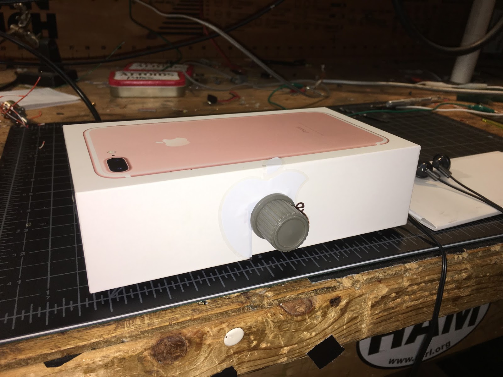
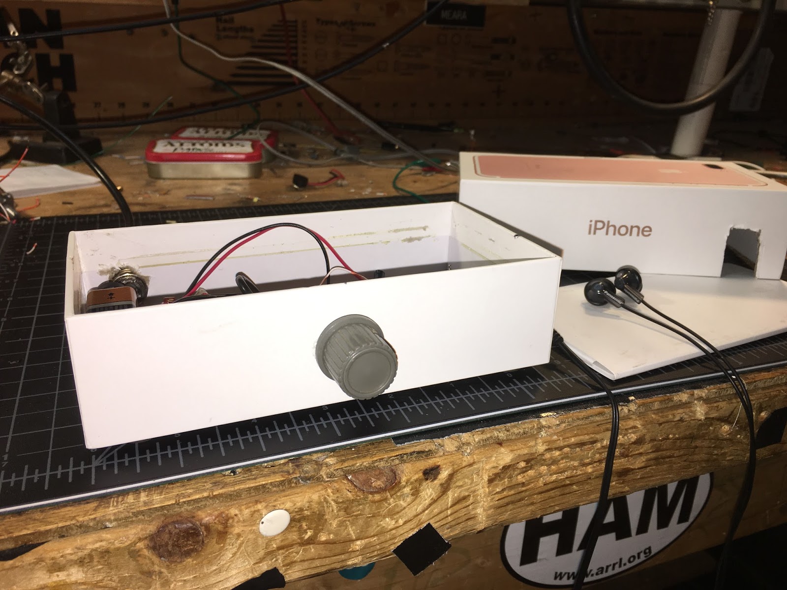
I think the Apple iPhone boxes have great potential as project enclosures. They are cardboard, but they are very rigid and solid. I decided to use them for a Direct Conversion receiver project I've had in mind.
This is a 40 meter DC receiver. No chips. Ceramic resonator VXO tuned by a varactor diode. 9V battery as the power source. Ear buds as the transducer. Passive, two diode, singly balanced detector. It sounds great -- so great that I may have to add a gain control.
The nice fit is no coincidence -- I cut the board so it would fit in the iPhone box.
Take a look at that top cover. It is all, well, empty. I could put another board in there, right? Maybe a balanced modulator, a mic amp and an RF amplifier. Then this thing would be a Double Sideband transceiver. We could even make use of the little microphone that comes with most of the ear buds.
I'm thinking that this might be the kind of project that people would like to take on this winter. Build the VXO first. Then the AF amp. Then the product detector and front end. At that point you've built a receiver. For extra credit you could go on to the transmitter. No need to use Apple boxes (but they are cool...) I will try to get the schematic done soon. My nephew John Henry will test the prototype.
"SolderSmoke -- Global Adventures in Wireless Electronics" is now available as an e-book for Amazon's Kindle.
Here's the site:
http://www.amazon.com/dp/B004V9FIVW
WHAT TO DO WITH 3CX3000F1
-
A number of years back, I was at the Sussex Hamfest, and a 3cx3000f1 jumped
out at me and said 'Take me home'.
I had an idea of building an induction heate...
Wireless sound mixing
-
I don't go out to see bands very much but recently we attended a dinner and
show by The Martini Set. It was an enjoyable evening but what caught my eye
was...
April 27, 2024. Tubes or Transistors?
-
A recent acquaintance and newfound friend suggested I cover the tube versus
transistor dilemma. Some Blog readers may even be saying why are you
wasting my...
Power standing wave null… solution
-
Power standing wave null… more left readers with “homework” to create the
Pfwd and Prev traces. Remember that Pfwd and Prev are interpretations in
the cont...
An Inline RF Step Attenuator for QRPp Work
-
I don’t need to explain the attraction of low power operation; if you’re
reading this, the chances are that you are already a convert. I’ve been
operating ...
Using an external clock with the RX-888 (Mk2)
-
*The RX-888 (Mk2) and external clocking*
*Figure 1:*
The RX-888 with external clock input *(right)*
The enable/disable switch is barely
visible behind the...
A 51S-1 Restoration Story
-
I came across my Collins 51S-1 in a big junkyard in Ankara, Turkey around
2012. It was in a pile with a lot of other electronic scrap, probably from
one o...
New QRP Cluster Online From OM0ET and OM6APN
-
By DX EXPLORER
DX EXPLORER
Paul OM0ET and Peter OM6APN recently launched a new cluster dedicated to
QRP operations. Have a look and I hope you will enjoy...
3D Printing The Hadley 114mm Newtonian Telescope
-
Yes, we’re building a 3D Printed Newtonian Telescope called Hadley. It’s
being printed in PETG and in the video below, I give a quick tour. My build
isn’...
3D printed project boxes
-
I have been busy with some other things that have kept me away from
electronics projects for quite a while. Now I can get back to them, but
realize I n...
Daylight Again – An all Analog Radio
-
What’s all this? In 10 seconds, A high performance, 7MHz, 5 watt SSB rig
Draws just 24 mA of current 90 dB dynamic range, 80 dB close-in dynamic
range 3D ...
Adding Enclosure to your sBitx Boards Order
-
The early buyers of the sBitx board set who bought it for $270 USD might
want to also add the enclosure (box) for in the kit. What you will now get
is a f...
Digi-chirp! Digital synthesis of ‘nostalgic’ CW
-
The bottom ends of 80, 40 and 20m are not what they used to be. For
starters, the busiest part is the digital segment where computers talk to
computers – l...
-
A Simple Speech Processor
(For QRP/SSB Homebrew Transceivers )
Over the last few weeks I had been thinking to build a small AF speech
processor to add to...
A New Look for your uBitx!
-
Adding a "Cool Blue" Display to your uBitx!
The standard "green background" with black lettering frequently reminds me
that I suffer from Chronic seasickn...