Podcasting since 2005! Listen to Latest SolderSmoke

Showing posts with label mixer theory. Show all posts

Monday, November 9, 2020

Improving the Product Detector in the Lafayette HA-600A

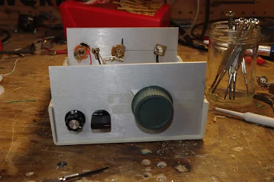
Diode product detector on the left, BFO amp in the right

As noted in an earlier blog post, I didn't like the sound of SSB and CW when using the product detector in my Lafayette HA-600A.  It just did not sound right.  The receiver sounded fine on AM with the diode detector.  But when I switched in the product detector, it sounded bad.  The BFO was fine.  The problem was there even when I used an external BFO.  And SSB sounded great when I just coupled some BFO energy into the IF chain and used the diode detector to listen to SSB.  My suspicions were focusing on the very simple BJT product detector. 

Steve N8NM built the HA-600A product detector both in LTSpice and in the real world.  It worked fine in both versions.  Steve even put the product detector into his S-38 receiver -- he reported it worked well there.  

I too built the thing in LTSpice.  Then I went and rebuilt the circuit on a piece of PC board.  I connected the new circuit to the HA-600A, using my external FeelTech sig generator as the BFO.  IT STILL SOUNDED BAD ON SSB.  

At this point I started Googling through the literature.  I found a promising article by Robert Sherwood in December 1977 issue of Ham Radio magazine entitled "Present Day Receivers -- Problems and Cures." Sherwood wrote: 

"Another area that could use additional work is the product detector.  As the name implies, its output should be the product of the two input signals. If BFO injection is removed, output should go to zero. If this is not the case, as in the Heath HW series, envelope detection is also occurring, which causes audio distortion." 

I checked my circuit.  When I removed the BFO signal from the product detector, envelope detection continued.  In fact, with the receiver in SSB mode, and with the BFO disconnected, I could listen to the music of WRMI shortwave.  It seemed that Sherwood was explaining well the problem I was having: Simultaneous envelope and product detection was making SSB sound very bad in my receiver.   What I was hearing just seemed to SOUND like what you'd get with a mixture of product and envelope detection: "scratchy" sounding SSB.  This also seemed to explain why SSB would sound fine when using the diode detector with loosely coupled BFO energy -- in that case it would be envelope detection only, with no ugly mixture of both kinds of detection.


So I built a better detector.  I had had great luck with the two diode one trifilar transformer singly balanced design used by both Doug DeMaw and Ashhar Farhan. I built the circuit using one of the trifilar toroids given to me by Farhan, and connected it in place of the original BJT product detector.  With the FeelTech Sig Gen as BFO, I got good results -- most of the signal disappeared with I disconnected the BFO.  Looking at the circuit, I realized that I was balancing out not the IF signal but instead the BFO signal.  To minimize envelope detection I needed to put the IF signal on the balanced input of the product detector (to L1 in the diagram above).  When I did this, envelope detection seemed to disappear completely and the receiver went silent when I disconnected the BFO.  


Finally, I needed to find a way to use the BFO in the HA-600A with the new product detector.  Obviously I needed more BFO signal -- I needed about 7 dbm, enough to turn on the diodes.  I converted the outboard product detector board into a simple amplifier and put it between the HA-600A BFO and the BFO input port of the new product detector.   This works fine. 

A few issues remain: 

1) The output from the HA-600A BFO through the above BFO amp (and across the 50 ohm resistor) is NOT a pretty 455 kc sine wave.  But the peaks of the distorted wave appear to be enough to turn on the diodes, and when I look at the voltages across each diode (on my two channel 'scope) I see mirror images -- one is on when the other is off.   Is this good enough? 

2) Moving the BFO input from L1 to the junction of the two 50 ohm resistors (that is actually a 100 ohm pot) has big implications for how this mixer works.  With the BFO energy going through the toroid, BOTH diodes are being alternately turned on and turned off.  But both are on, and then BOTH are off.  With the BFO energy going in through the other side, one diode turns on when the other is off.  I think the mixing result is the same, with AF coming out of the output port, but the way the mixer works in this configuration is very different. Does this sound right? 

Monday, October 26, 2020

VK3YE: Solving the Direct Conversion RX -- Double Sideband TX Incompatibility Problem


Peter:  

You have long been one of the leading gurus on DSB.  I remember absorbing all the info I could from your website when I was getting started in DSB back in 2001.   

It's great that you found  the article about DSB with inverted audio.   It would be very cool to build a transmitter with the inverted audio, then confirm that it could be received with a direct conversion receiver without distortion.  

The incompatibility of DSB TXs and DC RXs seems like a very cruel trick of nature.  There are only a few people in the world who think about this, and most of them are in the comments section of your YouTube video!  An elite group indeed.  

Back in 2015 your review of a DSB rig got me thinking about this incompatibility: https://soldersmoke.blogspot.com/2015/07/peter-parker-reviews-dsb-kit-and.html   

It is easy to see how a slight frequency difference between TX VFO and RX VFO would cause a lot of distortion, but similar distortion would be caused by a phase difference between the two VFOs.   AM SW Broadcast receivers try to minimize the effects of fading by using an internal oscillator to replace the wavering carrier -- but they have to have it exactly on frequency and locked in phase with the distant station's carrier. I have a little Sony portable that has this "synchronous detection" circuitry.   It is a complicated task and I don't think you could do it with the highly suppressed carriers of our rigs.  Inverted sidebands to the rescue!     

Thanks for the great video and all the tribal knowledge.  

73  Bill N2CQR

Thursday, October 15, 2020

Too Simple? Deficiency of the Lafayette HA-600A Product Detector?


I've been having a lot of fun with the Lafayette HA-600A receiver that I picked up earlier this month.  Adding to the mirth, I noticed that on SSB, the signals sound a bit scratchy, a bit distorted, not-quite-right. (I'm not being facetious;  this is an interesting problem and it might give me a chance to actually improve a piece of gear that I  -- as a teenager -- had been afraid to work on.) 

Before digging into the circuitry, I engaged in some front panel troubleshooting:  I switched to AM and tuned in a strong local AM broadcast signal.  It sounded great -- it had no sign of the distortion I was hearing on SSB.   This was an important hint -- the only difference between the circuitry used on AM and the circuitry used on SSB is the detector and the BFO.  In the AM mode a simple diode detector is used.  In SSB a product detector and BFO is used.  The BFO sounded fine and looked good on the scope. This caused me to focus on the product detector as the culprit. 

Check out the schematic above.  Tr-5 is the product detector.  It is really, really simple.  (See Einstein quote below.)  It is a single-transistor mixer with BFO energy going into the base and IF energy going into the emitter.  Output is taken from the collector and sent to the audio amplifiers. (A complete schematic for the receiver can be seen here: https://nvhrbiblio.nl/schema/Lafayette_HA600A.pdf )

I had never before seen a product detector like this.  One such detector is described in Experimental Methods for RF Design (page 5.3) but the authors devoted just one paragraph to the circuity, noting that, "We have not performed careful measurement on this mixer."  The lack of enthusiasm is palpable, and probably justified.  

A Google search shows there is not a lot of literature on single BJT product detectors.  There is a good 1968 article in Ham Radio Magazine:   http://marc.retronik.fr/AmateurRadio/SSB/Single-Sideband_Detectors_%5BHAM-Radio_1968_8p%5D.pdf      It describes a somewhat different circuit used in the Gonset Sidewinder.  The author notes that this circuit has "not been popular." 

To test my suspicion that the product detector is the problem,  I set up a little experiment.  I loosely coupled the output of a signal generator to the IF circuitry of the HA-600A.  I put the sign gen exactly on the frequency of the BFO.  Then, I switched the receiver to AM, turning off the BFO and putting the AM diode detector to work.  I was able to tune in the SSB signals without the kind of distortion I had heard when using the product detector.   

So what do you folks think?    Is the product detector the culprit?  Or could the problem be in the AGC?  Should I start plotting a change in the detector circuitry?  Might a diode ring work better?  


Saturday, September 19, 2020

SolderSmoke Podcast #225: Mars, uSDX, G-QRP, HP8640B, DX-390, Rotary Tools, Walla Walla SDR, MAILBAG

SolderSmoke Podcast #225 is available

http://soldersmoke.com/soldersmoke225.mp3

Mars,  West Coast smoke.

Pete's Activities: 
-- DC receivers.
-- CW offset
-- GQRP talk
-- The uSDX project

Bill's Bench
-- Sliding into the Vintage Test Gear Cult:  HP8640B . 
-- Fixing up and figuring out Radio Shack DX-390 receivers.  
-- 220 to 110 on a few remaining devices.     
-- Got myself a Dremel-like rotary device.  

Tech News: 
-- ARRL/TAPR Convention:  SDR project from Walla Walla University students.   Intuitive explanation for why desired and image freqs in a mixer come out with very useful phase differences.  

-- Chuck Adams' Amazing Lab Notebook.   Includes a simple circuit to measure resistance and Q in crystals.  FB. 

MAILBAG: 

-- Dino KL0S  SITSing in his shack, homebrewing 9 MHz filters  FB Dino.  Airborne! 
-- Dave NT1U sent us the famous 1968 QST Article by W7ZOI re DC RX.  
-- Ron K0EIA listening to SWBC staions with uBITX.  
-- Ted AJ8T  Korguntubes making a 12AX7 equivalent.  
-- Joel N6ALT sent me a nice DX-390 manual.  Thanks Joel
-- Bob KD8CGH alerted us to the uSDX project -- story on the blog. 
-- Craig AA0ZZ Sent a great message with insights on computer code -- I will put up on the blog. 
--Tracy KN4FHX reports on optimistic prognosis for SolarCycle 25.  Some chickens may have to be sacrificed.   
-- Stephen M0OMO Thanks SolderSmoke for rekindling interest in this hobby. 
-- Paul VK3HN  has a cool new rig -- The Prowler -- check it out
-- Steve N8NM working on his Sunbeam car -- Pete already knew about the carburetor synch problem.  N6QW knows everything. 


Friday, September 18, 2020

Mixer Insights using Propellers and Cameras -- From Walla Walla University. And SDR Design Info.

 
Pete Eaton sent us this video from the 2020 ARRL/TAPR Communications Conference.   I have the portion of interest cued up (above).  (The portion of interest begins at 6:59:46.)

There is a lot of really cool SDR design info in this video and in the associated paper  (the TAPR site says you have to pay the ARRL $9 for the paper, but in the comments someone says the papers will be available free after the conference).  

What caught my attention was the students' discussion of mixer action.   They use an analogy with a spinning propeller (the incoming RF) and a camera (triggered by the local oscillator) that samples the incoming signal at a specific rate. This is analogous to a Quadrature Sampling Detector. 

The really interesting part for me was how this analogy allows us to see how phase differences between the desired signal and the image signal arise.   These phase differences permit an SDR receiver (or indeed an old fashioned phasing Direct Conversion receiver) to reject the image while allowing the desired signal to pass.  

This is a key point in understanding mixers, and is really quite amazing. Before I saw this video, I had just come to accept (without understanding WHY) that the desired signal and the image signal would have phase differences, EVEN IF THEY WERE COMING OUT OF THE MIXER AT THE SAME FREQUENCY.  It is this phase difference that allows us to knock one down while allowing the other to pass. The propellers and cameras of Walla Walla University gave me insight as to how and why these phase differences exist.  

In their paper, the Walla Wall group mention uSDX, the project that is currently generating so much excitement around the world: 

Low-cost is not the only reason SDRs have become more popular among the amateur radio
community. More recently, Guido Ten Dolle’s μSDX open source transceiver has generated
increasing interest in quadrature sampling down-conversion SDRs in the homebrew QRP
community. Guido, PE1NNZ, was able to modify the QCX, QRP transceiver for SSB operation
with an efficient class-E amplifier, using only an ATMEGA328 and Arduino code to run the QSD
SDR. This groundbreaking work in this type of SDR has inspired various renditions of Guido’s
radio, fostering a lively groups.io group that can be followed at https://groups.io/g/ucx.

Kudos to Caleb Froelich, Dr. Rob Frohne KL7NA,  Konrad McClure, Joshua Silver, and 
Jordyn Watkins KN6FFS,  all of Walla Walla University,  for some really impressive work.  (BTW:  Rob tells me that back in the mid-90s he too built one of Rick Campbell's phasing receivers and wrote a QST article about it  (probably the first SDR article published by QST).  Details on the project are here: http://fweb.wallawalla.edu/~frohro/R2_DSP/R2-DSP.html

Monday, August 24, 2020

Video on the Strange Tuning of the Radio Shack DX-390 Receiver


I'm more of a single conversion guy myself, but in working with the DX-390 I came to appreciate the benefits (especially regarding image rejection) of the double conversion technique. 

While working on the DX-390, I discovered that the BFO control on the front panel DOES NOT change the BFO frequency.  It was fun to try to figure out why the designers did it this way.  It does make sense once you consider the limitation imposed by that PLL main tuning oscillator that only moves in 1 kHz steps. I hope the video explains things.  

Here is the drawing I used in the video: 


And here is a drawing that shows how a single conversion superhet with a fixed or switchable  (usually crystal-controlled) BFO works: 


Earlier this month  I did a blog post on my repair of a broken DX-390: 

Saturday, August 1, 2020

SolderSmoke Podcast #224: Mars. Spurs. Bikes. SDR. NanoVNA. Antuino. MAILBAG


SolderSmoke Podcast #224 is available:


1 August 2020

--The launch of Perseverance Mars probe with Ingenuity helicopter.
--China’s Tian Wen 1 on its way – radio amateur Daniel Estevez EA4GPZ is listening to it! 
--Sci Fi Books:  Mars Trilogy by Kim Stanley Robinson.  No skip on Mars :-(
--We have some sunspots!  SFI now 72 and the Sunspot number is 23. 

Bill's bench: 
--Conquering Ceramic Spurs in Q-31   Roofing filter -- sort of 
--NE602 for a Q-75 converter – Gilbert Cell. 
--Measuring low power levels out of NE602.  Antuino better than 'scope . 
--NanoVNA   Really cool stuff.  SDR in there. 
--Building a 455 kc LC filter from QF-1 rubble. Using LTSPICE, Elsie... 
--Reviving my bicycle AM radio – The “All Japanese 6”
--Understanding L Network impedance matching. 
--Bill’s new resistor kit from Mouser. Thanks to Drew N7DA. 

SHAMELESS COMMERCE:  PATREON, AMAZON SEARCH.  THANKS

Pete's Bench: 
--Lockdown Special 
--BPF work on SDR Rig
--I U W I H 

Mailbag:
VK3HN Summit Prowler 7
VK2EMU “The Stranger”
SM0P  HB uBITX in Dubai
AE7KI  Worked him in VK from London
ON6UU  EA3GCY’s 4020 rig
KA4KXX A Simpler Mighty Mite
W9KKQ M19 DMR
KD4PBJ Radio Schenectady
W3BBO 12AU7 Regen
KE5HPY Another 12AU7 regen
N5VZH Ne602 Converter
KY3R Wall Art
G4WIF  Spectrum Analyzer in your pocket
W2AEW  Talks to UK Club
KK0S Sent 455 Kc IF cans
KL0S Making 9Mhz filters
VU2ESE  Diving into simple SDR schemes
Dean KK4DAS  Amateur Radio Astronomy

Sunday, July 26, 2020

Alan Wolke W2AEW on IMD, NanoVNA and more (presentation to UK club)


This video is another reminder of how lucky we are to have Alan Wolke W2AEW as a fellow radio amateur, and as a teacher and mentor. 

In this video, Alan is talking to the Denby Dale Amateur Radio Society in Yorkshire, UK. 

The first part of his talk is about IMD products, the importance of 3rd order products, and the benefits of attenuation. 

The second part of the talk (after a few questions) is a look at the NanoVNA, which Alan cites as the "Toy or Tool of the Year."   

I learned a lot from both portions of the presentation.  I now find myself wanting an H4 model of the NanoVNA (bigger screen).  Or maybe even an F model.   Thanks to Alan, I now know what S21 and S11 means. 

Thank you Alan, and thanks to the Denby Dale ARS.  

73  Bill 
  

Friday, July 17, 2020

SSB Transceivers of the 1960s --- Videos by Mike WU2D


I liked both these videos.  Mike WU2D really does a great job.  He covers a LOT of technology and theory in two videos.  Thanks Mike!  

Saturday, April 11, 2020

Videos on the Q-31 Quarantine AM SW Receiver Project (and some pictures)


I've been making some short, stage-by-stage videos of my Q-31 receiver project.  So far I have seven videos.  They are here: 

https://www.youtube.com/user/M0HBR/videos

Please subscribe to my YouTube Channel.  And give me some "thumbs up" if you like the videos. 

Thanks.  SITS!  FlattenTheCurve!  73 


Pads from Pete, toroids from Farhan

The diode ring

Altoids-sized tins will hold the circuit boards

Stay In The Shack -- Or in the front yard. 


Monday, May 6, 2019

"The Bit Player" A New Movie on Claude Shannon

The Bit Player Trailer from IEEE Information Theory Society on Vimeo.

Thanks to Bob KD4EBM for alerting us to this.  As Bob put it, Shannon definitely had The Knack.  Check out the trailer (above)  for this new movie.   It looks like the IEEE is still working on the release plan for the film.  Does anyone have info on this? 

More info on the film here: https://thebitplayer.com/

Four years ago we reported on a video about Shannon: https://soldersmoke.blogspot.com/2015/09/claude-shannon-had-knack-video.html 

Thanks Bob! 

Sunday, April 14, 2019

Understanding Fourier Transforms


Lots of wisdom and insight here:

http://www.jezzamon.com/fourier/index.htm

Strongly recommended for those trying to understand mixers and harmonics. 

Saturday, March 24, 2018

SolderSmoke Podcast #203 Winter, Transceivers, Antennas, DC RX, uBITX, Mixers, 'fests, MAILBAG

N6QW in 1959. Building an SSB transceiver
SolderSmoke Pocast #203 is (FINALLY!) available: 

http://soldersmoke.com/soldersmoke203.mp3


24 March 2018

--The reasons for our delay. 
Winter, Computers, College, Family Trees, Lawyers....

-- Winterfest 2018 
-- Pete launches 2018    THE YEAR OF THE TRANSCEIVER
    http://n6qw.blogspot.com/
-- SDR -  Satan's Digital Radio?  
-- Direct Conversion Receiver Projects
-- Mixer Musings 
-- A Thailand Troubleshoot 
-- Nor'Easter knocks out Bill's Moxon -- An appliance replacement? 
-- Homebrew Electret Mics.  Seriously.  
-- uBITX Build with Rogier
-- Civilized Crystal Testing
-- Baofeng! 
-- DRAGNET

-- MAILBAG
KD4PBJ's REGEN 
N6ORS's SDR rig
Mike Rainey's DX-100

Monday, February 19, 2018

A Wonderful Troubleshooting Story -- Thailand, Mixers, a Simpson 260, Microwaves, and some Black Tape


My old friend was really fortunate to have had such a good Staff Sergeant instructor at Signal School, someone for whom the mixer trig was obviously not enough.  And our old friend obviously also benefitted greatly from having had a dad who set him up with a Simpson 260 and some handmade experimental glass diodes. Wow.  It all came together with some black tape in Thailand... 

Bill,

Enjoyed your latest blog. I remember your asking about mixers years 
ago.  I received much the same explanation from a Staff Sergeant 
instructor at Ft. Monmouth in 1967.  His example was a mixer with 
diodes, noting the need to have them forward biased by the LO supply.  
We worked out much the same waveforms as shown in your Blog and 
the concept became part of my 'intuitive' knowledge.

A few years later I was fighting 120hz hum on the baseband of an IWCS 
microwave system feeding USAF command at the Korat Air Base in
Thailand. The hum was pretty high level and causing inter-modulation 
problems on the 60 channels of signal sideband suppressed carrier 
being applied to the microwave system.

We ended up with a couple of DCA DoD employees being flown in to help, 
to their credit they were prior service and darn good at what they did.  
After three days of testing all parts of the microwave system with a 
very long distance and long duration phone call to the manufacture in 
Calif, they still had not found the trouble.

I had stayed working with the DCA guys all of the time, during the 
testing I noted the hum seem to lessen in strength with someone standing 
directly behind the radio bay.

I went around to the back and took a close look, Yep! the mixer diodes 
for the baseband order-wire were glass and exposed.

Put a length of black tape over them and the hum went away.  Not the 
power supply problem everyone was fixated on, it was diode photo 
sensitivity.  I guess we could have just turned off the florescent 
lights too.

When I was 10 years old my father showed me how to use a Simpson
260 to check diodes and early transistors*. We were on the floor of the 
living room with sunlight streaming in.  I saw the forward resistance change
a lot when the glass diode was in sun light vs shade. It was this memory 
that prompted me to try the black tape.

All the MW systems in SEA later received a MWO to change out the 
order-wire board and I found that the assembly was a non-standard part 
of the microwave system just for military use.  Civilian deployment of 
that microwave system had no need for the order-wire.

Thanks for the quick trip, for me anyway, down memory lane and the 
memory of being an electronics tech hero for all of two minutes. The DCA 
guys made me buy the first round at the club.

73  from an old friend....

Wednesday, February 7, 2018

Understanding Switching Mixers (as in the Ceramic DC RX)

W3JDR's Comment on my post about the DC RX mixer got me thinking.   He was right -- my explanation of the mixer action wasn't quite complete, especially as far as switching mixers are concerned.  I remembered that I had written about this in the SolderSmoke book.  Below you can see the part of the book in which I discuss switching mixers.  Realize that the two diodes in F5LVG's mixer play the same role as the two gates in Leon's circuit.  It will be worth your while to sit down with Leon's circuit diagram, his frequency chart,  and a ruler and really go through this so you can SEE and really understand how the two gates (or switching diodes) generate sum and difference frequencies.  

-----------------------

I guess I still yearned for clarity and intuitive understanding...  Time and time again, as I dug into old textbooks and ARRL Handbooks and promising web sites served up by Google, I was disappointed. 
Then I found it.
It was in the Summer 1999 issue of SPRAT, the quarterly journal of the G-QRP Club.  Leon Williams, VK2DOB, of Australia had written an article entitled “CMOS Mixer Experiments.”  In it he wrote, “Generally, mixer theory is explained with the use of complicated maths, but with switching type mixers it can be very intuitive to study them with simple waveform diagrams.” 
Eureka!  Finally I had found someone else who was dissatisfied with trigonometry, someone else who yearned for the clarity of diagrams.  Leon’s article had waveform diagrams that showed, clearly, BOTH sum and difference output frequencies.


Switching mixers apply the same principles used in other kinds of mixers. As the name implies, they switch the mixing device on and off.  This is non-linearity in the extreme.
Not all mixers operate this way.  In non-switching mixers the device is not switched on and off, instead one of the signals varies the amount of gain or attenuation that the other signal will face. And (as we will see) it does this in a non-linear way.  But the basic principles are the same in both switching and non-switching mixers, and as Leon points out, the switching circuits provide an opportunity for an intuitive understanding of how mixers work. 

Let’s take a look at Leon’s circuit.  On the left we have a signal coming in from the antenna.  It goes through a transformer and is then applied to two gate devices.  Pins 5 and 13 of these gates determine whether the signals at pins 4 and 1 will be passed on to pins 3 and 2 respectively. Whenever there is a positive signal on gate 5 or on gate 13, signals on those gaps can pass through the device.  If there is no positive signal on these gates, no signals pass.  Don’t worry about pins 6-12.


RF A is the signal going to pin 4, RF B is the “flip side” of the same signal going to pin 1.  VFO A is a square wave Variable Frequency Oscillator signal at Pin 5. It is going from zero to some positive voltage.  VFO B is the flip side.  It too goes from zero to some positive voltage. 
Look at the schematic.  Imagine pins 5 and 13 descending to bridge the gaps whenever they are given a positive voltage.  That square wave signal from the VFO is going to chop up that signal coming in from the antenna.  It is the result of this chopping that gives us the sum and difference frequencies.  Take a ruler, place it vertically across the waveforms, and follow the progress of the VFO and RF signals as they mix in the gates.  You will see that whenever pin 5 is positive, the RF signal that is on pin 4 at that moment will be passed to the output.  The same process takes place on the lower gate.  The results show up on the bottom “AUDIO OUTPUT” curve. 
Now, count up the number of cycles in the RF, and the number of cycles in the VFO.  Take a look at the output. You will find that that long lazy curve traces the overall rise and fall of the output signal.  You will notice that its frequency equals RF frequency minus VFO frequency.  Count up the number of peaks in the choppy wave form contained within that lazy curve.  You will find that that equals RF frequency plus VFO frequency. 

Thanks Leon!  

F5LVG's Glue-Built Mixer Transformer


One thing I forgot to mention:  In Olivier F5LVG's DC receiver article back in SPRAT 100, he casually mentioned building a transformer for his mixer by taking two inductors of the appropriate values and GLUING THEM TOGETHER.   What a great idea!  I had to try it.  I did.  Picture above.  It worked in my Ceramic DC receiver, but the trifilar transformer from Farhan in India worked better.  Perhaps the coupling was tighter.  But hey, it worked.  Three cheers for Olivier.    

Sunday, January 28, 2018

Building the Ceramic Discrete Direct Conversion Receiver #4 -- The Mixer


I think the most important stage of a direct conversion receiver is the mixer.   This is the stage that takes the RF energy coming in from the antenna and -- in one fell swoop -- turns it into audio.

It is important to understand how this happens.  I go into this in some detail in the SolderSmoke book.  To summarize: 

1) You have two signals going into a non-linear device.  The way in which the smaller signal passes through the device -- how much it is amplified or attenuated -- depends on the instantaneous value of the larger signal.  We are not just adding the two signals together.

2) The waveform that comes out will be a complicated repeating waveform.  We know from Fourier that any complicated repeating waveform can be broken down into sine wave components.

3) When you analyze the complicated repeating waveforms coming out of the mixer, you will find that the sine wave components include a frequency that is the sum of the two inputs and another that is the difference between the two.

So lets suppose we have a non-linear device.  We send in a signal from our oscillator at 7061 kHz. Coming in from the antenna we have a signal at 7060 kHz.   The non-linear device will produce outputs at 14121 kHz (sum)  and at 1 kHz (difference).  We are interested in the difference frequency.  We can HEAR that one.  We feed it into our audio amplifiers and we can copy the Morse Code coming in.  It will sound like a 1 kHz tone going on and off as the operator at the distant station presses his code key.  (We don't really have to worry about the 14121 kHz signal -- it is easily eliminated by filters and would never make it through our audio amplifiers.  And in any case we could not hear it.)

What can we use as a non-linear device?  In this receiver we will use diodes.  Diodes are  extremely non-linear devices. They can be used as on-off switches, with one of the signals determining if they are on (conducting) or off (not conducting).  When used like this they are "switching mixers." In essence, a larger,  controlling signal from the VFO will be turning the diodes on and off. Thus the signal coming in from the antenna will be chopped up by the switching action of the diode being turned on and off.  This is non-linear mixing at its most extreme.  It will definitely produce the sum and difference products we are looking for.

We could build the mixer with just one diode. You could apply the VFO signal to the diode to turn it on and off, and then feed the signal from the antenna into the same diode.   You would get the sum and the difference product out the other end.   You will see very simple direct conversion receivers intended for use in software defined radio schemes using just one diode. But this kind of circuit has a couple of serious shortcomingsq: it is susceptible to "AM breakthrough" and it is "lossy."

The circuit we are using addresses these problems by using two diodes.  To reduce loss, one conducts during half of the oscillator signal's cycle, the other during the other half.  Here LTSpice is ueful. You can model this mixer and see in the simulator how each of the diodes handles half of the oscillator RF cycle, with both contributing to the AF signal we want at the output (the difference frequency).   (The schematic above is from LTSpice but it is not ready for simulation.  For this you should replace the variable resistor with two fixed 500 ohm resistors, and add two oscillators -- one with the weak incoming RF signal and the other the strong local oscillator signal.)

The AM breakthrough problem is also addressed by the use of two diodes.  Here's the problem:  If you are on 40 meters, there will be strong shortwave AM broadcast signals coming in from your antenna.  Some will be so strong that they will get past your front-end filtering.  If you were using just one diode, that diode might demodulate the AM signal -- the AM carrier would mix with the AM sidebands and you would have an undesired audio signal heading for your AF amplifiers. Many of us have experienced this -- you are trying to listen to ham radio SSB signals, but you can hear China Radio International playing in the background. 

The two diodes take care of this easily. Look at the way an AM signal would reach the diodes. The carrier (and its sidebands) going through the top diode will be 180 degrees our of phase with the signal going into the lower diode. But the output of the diodes are joined together.  They will cancel out.  We say that for the RF signal coming through from the antenna, the circuit is "balanced."  That signal -- in this case the undesired AM signal -- will cancel out at the junction of the two diodes.

But to understand this circuit you must see what is NOT cancelled out.  The signal from the VFO is hitting each diode with the SAME polarity at the same time.  Look at the 1k variable resistor. So the signal from the VFO will NOT be cancelled out at the output.  Nor will the mixing products produced in the diodes.  That last sentence is the key to all of this.  The sum and difference products that result from the mixing of the signal from the antenna and the signal from the VFO SURVIVE.  They are not cancelled out.

We can easily select the one we want.  An RF bypass capacitor connected from the output of the mixer to ground will get rid of most of the VFO signal (7061 kHz) and most of the sum product (14121 kHz) while passing the audio to the AF amplifiers. 

When I built this detector I used a trifilar toroid out of a box of them that Farhan left with me back in May. I used two of the windings  secondary and one of the windings for the primary.  You might want to make a more simple transformer using an FT-43 type core.  I recommend W8DIZ as a source. 

I hope this explanation helps, and I hope I got it right.  Let me know if you see any errors in my explanation.  Tinker with the circuit when you build it.  You should be able to get it going.       

Complete Schematic


Saturday, May 14, 2016

A Lot of Soul in the Barbados Receiver

After a rather frustrating period working on the Hallicrafters S38-E, I decided to do something different, maybe work on something that isn't known as a "widow maker."    So pulled off the shelf an old Doug DeMaw Barbados Superhet Receiver.  "Barbados" sounds much nicer than "widow maker."  This design and this particular receiver have quite a history: 

-- DeMaw presented the receiver in the June 1982 issue of QST.  It uses six 40673 dual gate MOSFETS, an op amp for the audio, and a 250 Hz crystal lattice filter at 3.579 MHz using (YES!) colorburst crystals.  The local oscillator was a VXO. Doug's was for 20 meters, but his article provided a lot of info on how to put it on other bands.

-- I built one in 1997, building it for 20 CW.   That project is described here:

-- Sometime around 2000 I bought another one.  This one had been built on a FAR Circuits board by Dale Parfitt, W4OP.  Dale had used 5 MHz rocks for the filter and had used a varactor tuned circuit for the LO (with a DC-DC converter to increase the range).   I put it aside.  It sat on shelves in several countries for a number of years.  (I even have a THIRD one, a partially stuffed board that Michael Hopkins (the guy who wrote those great stories about Frank Jones coming back to life to retake the 5 meter band)).

-- I started working on it again around 2005. We were in London by then.  I put it on 17 meters using a capacitor-tuned VXO running up at around 23 MHz.   I did a quick and dirty broadening of the crystal filter by simply changing the capacitor values in the filter.  This worked, but obviously it needed refinement.  As I asked questions about this receiver, Dale Parfitt came to my rescue.  It took us both a while to realize that he was advising me on the receiver that he had built.  That was kind of cool.

-- I used the receiver with my first homebrew SSB transmitter.  I had them both running with separate VXO's, with crystals switched from the front panels.  I'm sure there were no other rigs like this on the air anywhere in the world.

-- By 2011 we were back in the US and I put my old homebrew SSB station back on the air.

-- In October 2014 I was building my first BITX rig.  I built it for 17 meters using a 23 MHz VXO.  I took the crystals out of the Barebones receiver.  Later that month I used an Arduino/AD9850 DDS arrangement as a digital crystal replacement: 
It worked, but it looked hideous.

-- By January 2015 I had learned a lot about how to characterize crystals and build filters.  I decided to take a shot at properly expanding the frequency response of the 5 MHz Barbados filter.  I measured the characteristics of the crystals and got the proper cap values for a 3 kHz filter.  When I tested it, the width seemed fine, but the ripple was more than I had expected.  Kind of disappointed I moved on to other projects.

-- Which brings us to today.  Escaping from the S38-E, I decided to put the Barbados receiver on yet another band.  With sunspot numbers in decline, I opted for 40.  And I wanted this to be an analog, L-C VFO project. No DDS, no PLL.  It would be all L and C for me, thank you! First I played around with the idea of running the VFO up at around 12 MHz, subtracting the 7 MHz sigs to get to the 5 MHz IF. But then I did a sweep of the filter.  First, there was a nice surprise -- the width AND the ripple were fine, just what I wanted (I must have had a measuring problem when I checked the ripple before).  And the skirt was MUCH steeper on the high side than on the low side.  This is why these filters are often called Lower Sideband filters.  You get better opposite sideband rejection if you use them as LSB filters.  

With the skirt situation in mind, I realized that running the LO at 12 MHz would not be a great idea. Our rule of thumb tells us that if we SUBTRACT the signal with the modulation from the signal without the modulation, we'll get SIDEBAND INVERSION.  So 7 MHz LSB would end up as 5 MHz USB.  Not great.  Plus, it is hard to get a VFO stable at 12 MHz.

So I opted to run the LO at around 2 MHz.  There would be no sideband inversion, and it would be easier to get the oscillator stable.   Wary of the threat of harmonics and spurs, I ran the receiver for a few days using an Arduino AD9850 at 2.125 MHz - 2.300 MHz.  It worked fine.

I now have the receiver running with a real Colpitts VFO.  The inductance is provided by an adjustable, shielded coil at around 1.5 uH (it was on the board) in series with a 3 uH toroid (type 6 yellow).  The feedback caps are at 2200 pf with a 1020 cap in series.  The main tuning cap is a small air variable with 73 pf max.  This only lets me tune about 40 kHz of the band, so, in a variation on the old Main Tune -- Bandspread technique, I have a rotary switch that adds capacitance in parallel with the main tuning cap.  I can now tune from 7.141 to 7.300.  The tuning rate is fine and I didn't have to mess with a reduction drive. 

More Barbados receiver blog posts here:
http://soldersmoke.blogspot.com/search?q=barbados

Kind of amazing that DeMaw designed this thing 34 years ago.  A lot of soul in this old machine.   


Tuesday, April 12, 2016

Some Thoughts on Noise and Receiver RF amplifiers from Scotland (and listening to sun noise on 2 meters!)

Bill,

Just listened to the latest SolderSmoke podcast where you asked why is it that an RF amplifier may be required on the higher bands but not on 40m and 80m for example.

At high frequencies the atmospheric and ionospheric noise levels are lower, so if noise figure of the receiver is reduced it will improve the signal to noise ratio you get from the receiver.  Adding gain -after- the mixer will not improve the noise figure of the receiver as it will be limited by the noise figure of the mixer. You need an RF amplifier which will itself have a lower noise figure than a mixer (certainly a passive mixer), to lower the total noise figure of the receiver to take advantage of the lower effective antenna noise temperature at higher frequencies.

This becomes very important at VHF and above, where antenna noise levels are much lower than at HF.

So, it isn't so much the overall gain of the receiver that is important with weak signal work, but the overall receiver noise figure which is determined to the largest degree by the first stage of the receiver.

There are spreadsheets available that will easily calculate the noise figure of cascaded receiver stages knowing the individual stage gains and noise figures.

One also has to be careful with the gain distribution throughout a receiver, if you have too much gain early on in an effort to improve the noise figure overall, you may overload the subsequent stages producing IMD with multiple strong signals. So there is a compromise to be met between noise figure and strong signal performance.

Going back to VHF and above if you have an antenna fed by coax with some appreciable loss then improving the receiver RF stage noise figure is not the best way to go because you are amplifying the signal after the loss the of the coax. What you need to do in those circumstances is to use a low noise masthead RF preamplifier which will give you gain and establish the noise figure of the receiver before the loss of the coax. Again there are spreadsheets to help with these calculations.

At VHF where an antenna is pointed at the horizon, the antenna sees the noise from the ground on the noise from the sky. As we elevate an antenna for EME or satellite working, then the effect of the ground noise should reduce (there will always be some due to side lobes) and then the receiver can benefit from even lower noise figure as the effective antenna noise temperature is now mostly determined by sky noise which at UHF is much lower than ground noise.

These last two days I have been able to see and hear the sun noise on my 2m receiver as the sun  set on my single 10 element yagi pointed at the horizon. Using WSJT's noise level scale I could see it  measure 12dB noise level and then once the sun set it dropped back to about 3dB noise indicated, most of that being local QRN from an antenna  sidelobe from my neighbour's house and his electronic devices which put out quite a bit of wideband noise on the band. (about 8dB above the lowest background level  I can normally detect).

To summarise, at LF where noise is high you don't gain anything by having a low noise figure receiver, and you actually lose out if you have too much gain early on as it will degrade strong signal handling.

At HF as manmade, atmospheric and galactic noise levels are lower, you can benefit from lower receiver noise figure and the way to lower your noise figure is to use lower noise amplifiers in the early stages of the receiver. Adding gain in later stages does not reduce the noise figure overall as the noise figure is largely determined by the first stage or stages.

At VHF using even lower noise figure devices in the RF stage will improve signal to noise.

Here is a practical test you can carry out. Switch between a dummy load and your antenna. If the background noise level increases when you switch to the antenna, then your receiver is sensitive enough, lower noise figure in the receiver isn't going to help.  If it doesn't increase then you have scope for improving the sensitivity of the receiver by reducing the noise figure of the receiver as you are no longer limited by antenna noise. 

Incidentally it is good to have a preamplifier that can be switched in an out of circuit so that you can reduce the noise figure when conditions allow ( low noise atmospheric noise levels for example), but switch it out if noise levels are high and signals are strong so that receiver overload and IMD don't occur. You can do something similar with an input attenuator to reduce strong signals where necessary.

I don't have a link here to the graph of manmade, atmospheric and cosmic noise levels versus frequency, but once you see one it becomes obvious why low noise figure receivers are not required at LF and MF generally.

73 from David GM4JJJ


Bill,

I found the article with graph of noise v frequency at last, in Ham Radio Magazine 1975!
A good read and as valid today as then.
I don't have a link here to the graph of manmade, atmospheric and cosmic noise levels versus frequency, but once you see one it becomes obvious why low noise figure receivers are not required at LF and MF generally.

73 from David GM4JJJ

Saturday, March 19, 2016

Great Video on Mixers


You know that you are sinking deep into The Knack when you watch a video like this one and find yourself thinking: "FANTASTIC!  WOW!  Now I know why square waves are better!" I really liked this one.  In the beginning I was kind of concerned about his refusal to explain how non-linear, non-switching mixers work.  He actually used the dismissive non-explanation that I've always found so disappointing:  "Blah, blah, blah... it's in the trig."   And he actually said, "Blah, blah, blah." But he more than made up for it when he got into the switching mixers.   Note that his drawing (at the start) of "Mixing by Switching"  attempts to show the waveform that results from an LO "chopping up" an incoming RF signal.  I always find that picture worth a thousand trig equations.

I also really liked his explanation of the benefits of rapid rise time in switching mixers, and how slow switching causes the diodes to spend some time in the non-linear part of their curves, giving rise (!) to IMD products (I'm paraphrasing).  You can really see why they say it is better to drive diode rings with square waves.  So stop trying to put low pass filters between your LO and the diode ring.  Square waves are your friends here. 

Mr. Marki seems to be one very cool EE.   And I'd like to hear more about his dad.  Here is some more about the Marki engineers:

http://mwexpert.typepad.com/markimicrowave/

Designer: Douglas Bowman | Dimodifikasi oleh Abdul Munir Original Posting Rounders 3 Column