Just go to http://soldersmoke.com. On that archive page, just click on the blue hyperlinks and your audio player should play that episode.
http://soldersmoke.com
6 weeks in the DR for Bill One contact on uBITX. More SW listening. Repaired my Chrome Book in Santo Domingo! Christmas Present for All: James Web Space Telescope launch
I spent most of January in the tropics, away from my workbench. This seems to have had a good effect on my 17 meter split TX/RX project. As I was leaving, heading south, I was thinking about several difficult options to deal with my spur problem (see previous blog posts). I thought about turning the transmitter into a transceiver by building a receiver board. I thought about putting San Jian frequency counters on both the transmitter and the receiver, then doing a visual numerical "netting" by just putting the two devices on the same frequency (I actually ordered 3 San Jian counters). The counter option was even more complicated than it at first seemed -- I would have to build a converter to shift the RX VFO frequency up. VK2EMU suggested a tube type "Magic Eye" (interesting idea, but also complicated). This was getting out of hand.
When I got back home, I took a new look at the problem. I decided to take one more shot at suppressing the 8th harmonic of the carrier oscillator. I had already built a new oscillator and buffer using the circuit from Farhan's BITX20. And I had put it in a metal box. Now I decided to do three things:
1) Tighten up the low pass filter at the output of the buffer by moving the cutoff frequency lower (to around 7 MHz) thereby getting a bit more suppression at 41 MHz
2) Try putting a series LC shunt circuit tuned to 41 MHz at the output of the carrier oscillator (between the oscillator and the buffer).
3) Reduce the voltage to the oscillator/buffer. I have this on a pot, so I can adjust it down to the point where the remnant of the harmonic is no longer audible, while keeping the main carrier osc signal sufficiently strong.
It seemed to work. I could now hear the desired frequency for spotting, without the confusing tone from the spur.
Why had I been able to do this back in 2002 in the Azores using a simple trimmer cap to ground? My guess is that I was using my Drake 2-B as the receiver. The trimmer cap to ground may have reduced harmonic output. And I was probably cranking back the RF gain on the 2-B to the point where I could hear the desired signal but not the remnants of the spur. I have no RF gain control on the Barebones Barbados receiver that I am using in this project.
So, what's the lesson from all this? Well, if you are faced with a serious technical problem, and you find yourself considering complicated and difficult solutions, go to the Dominican Republic for about a month (especially if it is January or February), and then take another look at the problem when you return. If you are unable to travel this far or for this long, taking a walk or taking a weekend break from a troublesome problem will likely have a similar mind-clearing effect.
The video above shows part of a February 1, 2022 QSO with Gar WA5FWC using the split TX/RX 17 meter rig. Gar is an amazing long-time SSB homebrewer who got his start with phasing rigs back in the day.
As often happens, I may have jumped the gun in declaring the exorcism of my 17 meter transmitter to be a success. As readers of this blog will recall, my problem was that when trying to "net" my separate 17 MHz receiver and transmitter, at around 18.116 MHz I could hear more than one tone as I tried to get to zero beat. The 8th harmonic of my 5.176 MHz carrier oscillator was mixing with the 23 MHz VXO signal and producing a spur. I could probably knock the level of this spur down below FCC limits, but -- and here is the problem -- I probably could never knock it down to the point that it would not be audible in the sensitive receiver that sits right next to the transmitter. So this is really a netting problem, not really a spur problem.
I don't want to try another filter frequency -- I have VXO crystals that really work only with a filter at 5.176 MHz.
So here is my current idea: Build a receiver board and turn this thing into a transceiver. Switch with relays the input and output of the 5.176 MHz filter, and use relays to switch to the receiver board the VXO and carrier oscillator signals.
Making this thing a transceiver would eliminate the need for netting. This should solve my problem.
First, thanks to all who sent in suggestions. They came in literally from around the world, and this is a demonstration of the IBEW in action. I used or at least tried all of them. They were all good ideas.
Following Vasily Ivananeko's pseudonymous suggestion I rebuilt the carrier oscillator (apologies to G3YCC). I used the carrier oscillator/buffer circuit from Farhan's BITX20.
Henk PA0EME said I should look at the signal level at the input ports of the NE602 mixer. Henk was right --- the VXO input was far too high. I lowered it, but the problem persisted.
At first, I thought that the spur in question was so small that it would not show up on the air. I could not see it in the TX output using my TinySA spectrum analyzer. That was good news and bad news: Good that it was not showing up on the air, bad that I could not see it in the TinySA and use that image in the exorcism.
At first I thought that the spur was being caused by the 10th harmonic of the carrier oscillator and the third harmonic of the VXO. This seemed to fit. So, following VK3YE's sage advice, I built a little 69 MHz series LC trap (using a coil sent by AA1TJ, on a board CNC'd by Pete N6QW). That trap succeeded spectacularly in crushing the 10 harmonic. Look at these before and after shots on the TinySA:
Before Trap
After Trap
Spectacular right? But guess what? The problem was still there.
I scrutinized the situation once more. I realized that the spur would be more visible if I put the TinySA on the input of the transmitter's PA (a JBOT amp designed by Farhan) as opposed to putting it on the output. Watching the spur and the needed signal move in the TinySA as I tuned the VXO, I realized that they were moving in opposite directions. This indicated that the spur was the result of a carrier oscillator harmonic MINUS a VXO-generated frequency (as the VXO frequency increased, the spur frequency decreased). Looking at my EXCEL spread sheet, I could see it: 8th harmonic of the carrier oscillator MINUS the main output of the VXO.
To confirm this, I plugged the values into W7ZOI's Spurtune program. Yes, the spur popped up and moved as predicted.
For further confirmation I shut down the carrier oscillator by pulling the crystal from the socket, and then just clipped in a 5.176 MHz signal from my HP-8640B signal generator (thanks KB3SII and W2DAB). Boom! On the TinySA, the spur disappeared. Now I at least knew what the problem was: a harmonic from the carrier oscillator.
Following good troubleshooting practice, I turned off the gear and went to bed. When I woke up, an idea came to me: Before launching into a lot of filtering and shielding, just try running the carrier oscillator at a lower voltage, seeing if doing so might reduce the harmonic output. I disconnected the carrier oscillator board from the main supply and clipped in a variable voltage bench supply. Watching the signal on my TinySA, I watched as the spur completely disappeared as I reduced the voltage from around 13V to 10V (see video above). The main signal frequency level did not change much. I tested this by listening for the hated extra tones. They were gone. Exorcised.
Key lessons:
-- Spur problems are difficult to troubleshoot. Armstrong's superhet architecture is, of course, great, but this is definitely one of the pitfalls. Single conversion makes life easier. IF selection is very important. Choose wisely!
-- When looking at the TinySA as you tune the rig, pay attention to which way the spur is moving. This provides an important clue regarding the combination of harmonic you are dealing with.
-- The TinySA is a very useful tool. It seems like it is easier to use than the NanoVNA (which is also a fantastic tool).
-- It can be fun and rewarding to re-visit old projects. In the years between original construction and the re-look, new test gear has become available, and the skill and experience of the builder has improved. So problems that once seemed insurmountable become fix-able.
-- Thinking through a problem and thinking about possible solutions is very important. It pays to step away from the bench to think and rest. Rome wasn't built in a day. Here's a rough block diagram that I drew up (noodled!) while trying to figure out this problem:
Here we see them struggling to find the proper frequency for one of the oscillators in a dual conversion UHF receiver from the Apollo program. For the VCO, they needed a crystal in the 23 MHz range. They faced the same questions we face: Series or parallel? Load capacitance? Fundamental or overtone?
It just so happens that at this moment I have on my bench the 17 meter SSB transmitter that I built some 20 years ago. And the VXO in it uses crystals in the 23 MHz range. TRGHS. (More on the spur problem with this rig soon. The solution does involve the 23 MHz VXO.)
Very cool that CuriousMarc found a manufacturer still willing to produce custom-made crystals. JAN flashbacks! LapTech Precision in Canada: https://www.laptech.com/index.php
The video above is Episode 8 in the Apollo Comms series. If you go back one episode, you can watch Marc and his assistant troubleshoot the NASA Apollo UHF receiver. They use very familiar troubleshooting techniques. This reminded me a lot of what we do with older, potentially modified gear. They were able to figure out what was wrong and how a mod had changed things. This set the stage for the crystal replacement selection we see in Episode 8. Here is Episode 7: https://www.youtube.com/watch?v=87qA41A_Ies
Note: The frequencies in this Apollo receiver were listed in Megacycles, not Mega Hertz.
Thanks to Bob Scott KD4EBM for alerting us to this.
I built the transmitter almost 20 years ago. It is in the larger box, which originally housed a Heathkit DX-40. There is a lot of soul in that old machine. Details on this construction project are here: https://soldersmoke.blogspot.com/2021/12/junk-box-sideband-from-azores-2004-qst.html(The smaller box is a Barebones Superhet receiver set up for 17 meters.)
In the 2004 QST article I discuss a problem I had with "spotting" or "netting." This is something of a lost art, something that you had to do back in the pre-transceiver days, when running a separate transmitter and receiver. This was how you got the transmitter on the receiver's frequency. Essentially you would turn on the carrier oscillator and the VFO and let a little signal get out, enough to allow you to tune the VFO until you heard zero beat on the receiver. My problem was that around one particular frequency, I would hear several zero-beats. This made netting the receiver and the transmitter hard to do.
Important note: This is really just a problem with the "netting" or "spotting" procedure -- the problematic spur does not show up in any significant way in the output of the transmitter. I can't see it on my TinySA. But it is strong enough to be heard in the unmuted receiver sitting right next to the transmitter. And that creates the netting problem.
In the QST article, I said that I noticed that the problem seemed to be centered around 18.116 MHz. As I approached this frequency, the tones -- desired and unwanted -- seemed to converge. That was an important clue. In the article I said I thought that I could eliminate the problem with just one trimmer cap to ground in the carrier oscillator, but looking back I don't think that this really fixed the problem.
I recently took a fresh look at it. Exactly which frequencies were causing the unwanted signals that appeared in my receiver?
I used an Excel Spread sheet to find the culprits.
The first column shows the carrier oscillator and its harmonics. The second column shows the VFO when tuned for a signal at 18.11668 MHz (23.2927-5.17602), along with its harmonics. Check out the 10th harmonic of the carrier oscillator and the third harmonic of the VFO: 69.8781-51.7602 = 18.1179. Those two harmonics would produce the problem I had been experiencing.
I turned to one of Wes Hayward's programs for confirmation. Spurtune08 came in the EMRFD software package. Here is what I saw when I plugged in the above frequencies:
You can see the little spur off to the left of the main signal. In the program, as I tune the 23 MHz VFO frequency, the spur moves closer to the main frequency as I approach 18.116 MHz, just as it does in the real rig. Note that I have only turned on the 10th harmonic of the carrier oscillator and the 3rd harmonic of the VFO. Spurtune08 is very useful. Thanks Wes!
So, what is to be done? For now, I am just restricting my operations on 17 meters to above 18.120 MHz. (I worked several DX stations with it on December 27.) But obviously I need to fix this. This rig needs an exorcism. I think I only need to get rid of one of the harmonics, and the 10th harmonic of the carrier oscillator seems easier to kill. I'm thinking of putting the carrier oscillator in an Altoids box, and then adding some filters to knock down the 10th harmonic.
Here is the G3YCC schematic that inspired this rig. I used G3YCC's carrier oscillator and balanced modulator circuits, just using a 5.176 MHz crystal and changing the tank circuit in the collector:
How would you folks knock down that 10th harmonic?
The French "repairability index" is an interesting concept. I wonder how modern ham radio "radios" would score. I think our homebrew rigs would max out the index.
Pete has commented on manufacturing processes that do (or don't) factor in access for repair.
One of the recent horror stories we've heard is about a certain manufacturer of mobile phones. It seems that they have designed the phones so that if you dare to replace a broken screen, the new screen won't work unless you de-solder the associated chip, then re-solder in the SAME CHIP.
A cosmically interesting troubleshoot. But I'm not sure about their explanation. Why would the intermod disappear when they moved the Parkes Radio Telescope off of Proxima Centauri?
I think a good troubleshoot is almost as satisfying as a successful homebrew. And we can sense that high level of satisfaction in Pete N6QW's description of his repair of a Collins KWM-1:
I liked Pete's troubleshoot/repair story, but -- as is often the case -- I struck by his turn of a phrase. I think Pete has added something important to the SolderSmoke lexicon:
THE SHAME SHELF
Most of us have a shelf like this. I have an HW-101 on mine. Pete shows us that there is hope -- there is path off of the shame shelf. You just have to know stuff.... Or have IBEW friends like Pete who can advise you.
Wow, Scott got his Mate for the Mighty Midget receiver to work and he is obviously overjoyed with the result. All of us who have struggled with a homebrew project know just what this feels like. And it is very cool that Scott got some useful guidance from Charlie Morris in far-off New Zealand. Congratulations Scott. I'm really glad you stuck with it.
Scott's success comes at a good time: Pete N6QW is building W4IMP's three tube "IMP" SSB transmitter (also from the 1960s). I accept responsibility for naming Pete's project: It will be known as "Pete's IMP" or, memorably, "The PIMP." For a look at Pete's rig go here:
Scott had problems getting Lew McCoy's 455 kc crystal filter to work. So did I. It turns out that this is a very old problem, going back to World War II. In Don Stoner's 1959 "New Sideband Handbook" on page 54 he writes of homebrew filters in the 400 to 500 kc range:
"Inexpensive crystal filters constructed from war surplus FT-241 type low frequency crystals are very popular with the 'do it yourself' hams. These CT cut crystals have been plentiful and relatively cheap for a number of years and are in the hands of many Amateurs. The general run of war surplus crystals may or may not be good. Experience has shown that one out of four of these crystals are usually defective in one way or another."
Stoner was writing just 14 years after the war. Add another six decades to the age of these crystals -- often decades spent in musty basements -- and you can imagine the percentage of bad 455 kc FT-241 crystals increasing. So I think Scott is wise to seek an alternative to McCoy's crystal filter.
Scott's original build of the MMMRX receiver is just so nice. In the video he says he plans to go back to it after he gets the expanded version fully functional. He should definitely do that -- his original version looks so good. I think it is probably very close to working properly.
This amazing 10 minute video captures very well the joy of fixing broken things. It comes to us through a recommendation from Paul VK3HN in Melbourne, Australia. Thanks Paul.
I often tell the story of the OT (probably now an SK) who at hamfests would ask if a piece of old gear was working. If the vendor answered honestly and said no, OT would reply, "Good, I pay extra for that." He too liked to fix things.
We don't get a lot of mail from Darwin, Australia, so the message coming in from Phil VK8MC immediately got our attention. When I looked into the details I realized that it was very SolderSmoke-relevant. The Guardian article that Phil cited even mentions hobbyists tinkering with electronic devices in their sheds (that would be us!). Phil points to the connection between our repair efforts and the struggle to save the planet: "It's not just a hobby, it's an ethical position which contributes to the well being of the planet. A higher calling indeed!"
I picked this generator at the Kempton Park rally in London many years ago. I use it quite a bit, not only for circuit testing but also as an easy way to get my homebrew BITX rigs to send a signal so that I can adjust my antenna. I just plug this thing into the mic jack, crank in a small amount of 1 kHz audio, and I am ready to minimize SWR.
It never gave me any real problems until last week. I opened it up and examined the circuitry for the first time. Lots of mystery chips in there. Fortunately they are all socketed. Thank you Maplin.
Even without really knowing how each of the ICs work, it was easy to troubleshoot. See the schematic in the article that begins on page 21 in this .pdf:
My Rigol scope showed a good signal going into and coming out of IC8, the LF351 op-amp. From there the signal goes to IC5 a 4066BE. But nothing was coming out of IC5. Thus IC5 was my lead suspect. I put in a quick order to Digikey. A couple of days and a few bucks later the chips (as always, I ordered several) were on my doorstep. Within a few minutes IC5 was replaced and the generator was as good as new.
One annoying problem with this generator is that it has no automatic shut-off circuitry. So if I forget to turn it off, I soon have to buy two 9V batteries. Tony G4WIF suggested a simple timer circuit. I may do that soon. Or, given that we are already on the IC dark side with this project, there is this: https://www.youtube.com/watch?v=C4C2H_3BU3o&feature=youtu.be
I recently find myself replacing a lot of chips in various rigs and devices in my shack. It seems that chips go bad more frequently than discrete transistors or even tubes. But maybe I'm just using older gear with older, more fragile chips. What do you folks think?
A reading from "Conquering the Electron."Germanium vs. Silicon.
Bill’s Bench:
The KLH Model Twenty-one II.Acoustical Suspension.First receiver
WITH A PILLOW!Bad speaker? Blown AF amp
finals.Hot heat sink.VBE Multiplier. Desitin.
Tony Fishpool’s recommended LM386 boards.10 for 11 bucks.Nice.They
work. Pictured in the Amazon ad at the
upper right of the SolderSmoke blog page.
Putting a digital display on the Lafayette HA-600A
Test gear trouble. My
Radio Shack multimeter getting flaky.I
many need something better.Auto
ranging? My beloved Maplin AF generator died – will have to fix. I need that
thing. Probably a bad chip.Good thing they are socketed.
I almost forgot about SKN!But I remembered and I made one contact with the HT-37 and Drake 2-B.
Pete’s Bench:
Presentation to RSGB on Homebrew.
TenTek Troubleshoot.
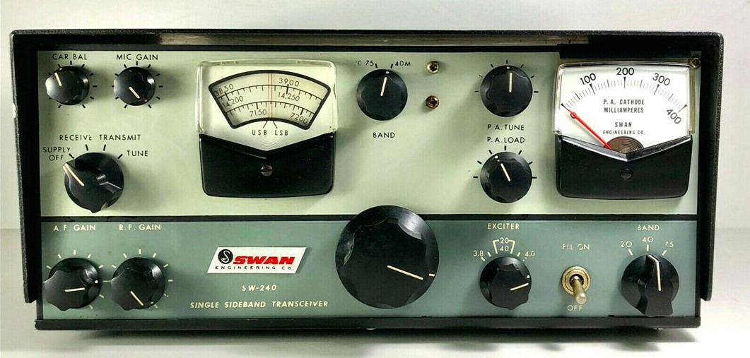
Swan 240?Looking
nice.
SDR adventures.
MAILBAG
Bill N8ET sent me some really nice Showa 9 MHz 8 pole
crystal filters.
Kevin AA7YQ Smoke jumper!Building a hybrid SDR.HDR rig.Launched blog. FB
Nick M0NTV working on similar HDR/SDR project.Great video.
Grayson KJ7UM Hollow State Design – Launched a new
blog.Very FB!
Thomas K4SWL of SWL Post blog.Kearsarge Mountain Transmission system.And recent events.
Peter VK2EMU Poetry.CW poetry.
Pete WB9FLW looking at DSB rigs…
Drew N7DAFeels not
like a real ham because he hasn’t built a quad from bamboo. Which type of
landscape bamboo is best for antennas?
Ryan Flowers of MiscDotGeek.Com blog is also watching the
Tally Ho YouTube videos of Leo Sampson. Wants to put a WSPR beacon on the Tally
Ho.
Joe KF5OWYWorking
with diode ring mixers, trying to see the mixer action on his ‘scope. 1 and -1!
Jim AB9CN sent a cool idea about how to do a 20/17 Moxon.
Roy GM4VKI – I thanked him for his article in SPRAT about
putting a 2n3904 on the output of an NE602 10P mod. Brilliant.
Roger Hayward Told him that I really liked his Dad’s recent
web site updates.
Farhan – Jokingly cursed me for showing him the Oscillodyne
regen of Hugo Gernsback and Jean Shepherd. “Now I will have to build this!”
I've been having a lot of fun with the Lafayette HA-600A receiver that I picked up earlier this month. Adding to the mirth, I noticed that on SSB, the signals sound a bit scratchy, a bit distorted, not-quite-right. (I'm not being facetious; this is an interesting problem and it might give me a chance to actually improve a piece of gear that I -- as a teenager -- had been afraid to work on.)
Before digging into the circuitry, I engaged in some front panel troubleshooting: I switched to AM and tuned in a strong local AM broadcast signal. It sounded great -- it had no sign of the distortion I was hearing on SSB. This was an important hint -- the only difference between the circuitry used on AM and the circuitry used on SSB is the detector and the BFO. In the AM mode a simple diode detector is used. In SSB a product detector and BFO is used. The BFO sounded fine and looked good on the scope. This caused me to focus on the product detector as the culprit.
Check out the schematic above. Tr-5 is the product detector. It is really, really simple. (See Einstein quote below.) It is a single-transistor mixer with BFO energy going into the base and IF energy going into the emitter. Output is taken from the collector and sent to the audio amplifiers. (A complete schematic for the receiver can be seen here: https://nvhrbiblio.nl/schema/Lafayette_HA600A.pdf )
I had never before seen a product detector like this. One such detector is described in Experimental Methods for RF Design (page 5.3) but the authors devoted just one paragraph to the circuity, noting that, "We have not performed careful measurement on this mixer." The lack of enthusiasm is palpable, and probably justified.
To test my suspicion that the product detector is the problem, I set up a little experiment. I loosely coupled the output of a signal generator to the IF circuitry of the HA-600A. I put the sign gen exactly on the frequency of the BFO. Then, I switched the receiver to AM, turning off the BFO and putting the AM diode detector to work. I was able to tune in the SSB signals without the kind of distortion I had heard when using the product detector.
So what do you folks think? Is the product detector the culprit? Or could the problem be in the AGC? Should I start plotting a change in the detector circuitry? Might a diode ring work better?
This thing has been half-broken for a long time. I needed to get the input for 40 MHz - 650 MHz working I got the a replacement SP8630B Plessey divide-by-ten counter chip on e-bay, and yesterday I extracted the old chip and put in the replacement. I took great care NOT to solder this one in upside down (as I had done with another chip replacement in this counter). I used solder flux and solder wick to gradually get the pins free of the board. (You can see the old chip in the picture above.)
As to what happened to the original SP8630B chip, John over on the Vintage Test Gear Facebook page wrote:
The Plessey SP8630A/B is an ECL divide by 10 prescaler, with a upper working frequency of 600MHz. That generation went out of production in the late 1980s. Plessey was bought by a Canadian company now called Micrel. You may be able to find one from one of the specialist obsolete component companies, but it may be dead on arrival. Those ECL ICs had a fairly high mortality rate if they are very old.
It is the old story of "metal migration". In early semiconductors very small impurities in the silicon structure cause minute bits of the metallisation to leach out into the essentially non-conducting silicon insulation. Many old devices, although they have never been used, were found to be very leaky and this degrades the gain of the active devices. The worst types are the very old Germanium transistors.
As the semiconductor scientist learnt more about the super cleanliness required and the better purification of the metals the problem tended to improve. The Marconi company I worked for back in the 1980s had a real problem with comms satellites failing after a few years of service. Of course you can't go up there and swap out the faulty devices. Accelerated ageing of a backup satellite showed that some devices just stopped working after being subjected to high and low temperature cycling, which is a common problem with satellites in orbit!
I am liking this little machine more and more. It is very simple -- no microcontroller, just a collection of gates. I discovered that the main main crystal oscillator is actually built inside a little oven to keep the temperature stable -- oscillator and the oven stay on as long as the counter is plugged in, even when the device is switched off. I calibrated the counter with WWV and with my HP8640B and with my little Feeltech sig gen counter. I wish I knew how to calibrate the counter in the Rigol DS1102E oscilloscope.
This is such a beautiful project: it involves DSB, homebrew, troubleshooting, George Dobbs, SSDRA, J310s, a box kite, and ham radio nostalgia. I was struck by how similar the Bitsy looks to some of my own DSB creations (but the Bitsy is nicer). I'm really pleased to find a DSB project coming out of the UK -- when I was there, DSB was kind of frowned upon by spectrum preservation zealots. I say there is plenty of room for the very few homebrew DSB rigs that will ever grace the airwaves with their presence. Thanks John. Have fun with all your projects. 73 Bill
Hi
Bill
In
the early 80's I built and experimented with Direct Conversion Receivers and
had a lot of fun with them. I came across a 40M DC cw transceiver by the late
Rev. George Dobbs in a Practical Wireless magazine and decided to build it.
Whether I was just lucky I'm not sure but it worked first time and I had
several cw contacts with it. It was called “The PW Severn”. I then discovered
DSB and looked into modifying the wee rig. I gave George a phone, no internet
in those days, and explained what I was proposing to do and if there was any
advice he could offer. His reply was ,
“it should work so try it and see, any problems get back to me”. It
worked and I had a lot of fun with it. I used to take it portable and with a
box kite to support a long wire and worked all over Europe.
It was after reading and learning about
circuits and home brewing I wondered if I could design and build a DSB
transceiver of my own. I had plenty of articles and most importantly a copy of
Solid State Design, now well thumbed.
So the “Bitsy” was born. It is an 80M DSB
transceiver. The PA produces about 2 watts. I took what I thought was the best
for each module and built it using six circuit boards which I designed and
etched myself. Nowadays I use the Manhattan method for one of circuits. It is
much easier and quicker.
Like most home brew projects, the fun is in
the building and the wee rig lived in a box for several years. Probably over
30. My doesn't time fly. I came across it again while looking through my boxes
and decided to give it an airing. Expecting it to work on power up I was quite
shocked when it produced nothing on both receive and transmit. After staring at
it for a couple of minutes I unscrewed the lid and studied the wiring for a dry
joint. Nothing so I switched on my Digital Multimeter and Oscilloscope. I soon
found out that the output from the VFO was missing. The VFO uses one FET and
two PNP Transistors for the buffers. The scope soon proved that the FET was
faulty. I used an MPF102. These are hard to get so I replaced it with a J310.
While I had the VFO out I also replaced the 9.1v zener diode, which provides a
regulated voltage for the FET, with a 78L05 connecting the centre pin via a
580ohm resistor to earth. This gives me a 9.3v regulated supply for the
oscillator. It is now back in full working condition.
With the Covid 19 epidemic I, like a lot of
the Amateur Radio fraternity, am spending a lot of time in the shack and
looking for new projects. I am buying back my old FT200 which was my first rig.
An old friend and lapsed amateur has still got it and agreed to sell it back to
me. It is still in a good condition for being nearly 50 years old and just
needs some TLC. When it is finished it will take pride of place beside my
restored Heathkit SB104A. And they say nostalgia is not what it used to be!!
The HP8640B is a complicated machine. Above you see just one sub-assembly, and the page from the manual that describes it. This is what I've been working on. The little spring "tine" fell out of one of those discs behind the two control knobs. So I had to open this thing up, find the spot from which the tine had fallen, and glue it back in.
I used Gorilla Super Glue, followed 24 hours later by a dab of JB Weld "minute weld" dual epoxy. One of the other tines was about to fall out, so I went ahead and gave all the tines in this assembly the glue treatment. ( I bought some "Weld On" acrylic cement but the warnings on the label were quite sobering. So I left that can sealed up.)
This morning I put the thing back together. This is not easy. At one point a spring popped and a tiny metal part that is probably irreplaceable seemed to fly away into the black hole that is the shack's carpet. I had just about given up hope when I found the thing sitting right in front of me on the bench. TRGHS.
The HP8640B fired up right away without trouble and the internal frequency counter is working fine.
As I noted in the last SolderSmoke podcast, a very nice community devoted to the HP8640B has developed around the world. Here are some of the notable participants:
Bill at Electronics Revisited is a very nice fellow with lots of experience on the HP8640B. He offered to sell me a replacement unit for the assembly pictured above. If you have an ailing HP8640B and are looking for someone to work on it for you, Bill is the guy you should talk to: http://www.electronicsrevisited.com/ He also very kindly offers to answer any questions you may have about the HP8640B.
Here is the e-bay page of the fellow in Bangalore who makes the brass gears. Mine are on the way!
And of course special thanks to Dave VE3EAC who alerted me to the falling tine problem and put me on the path to a successful repair.
The gears should be here in a few weeks, so that will be another opportunity to work on this HP8640B. Also there are some tines in the attenuator assemby that might reinforce with the glue treatment.
"SolderSmoke -- Global Adventures in Wireless Electronics" is now available as an e-book for Amazon's Kindle.
Here's the site:
http://www.amazon.com/dp/B004V9FIVW
April 29, 2024. The J310 Direct Conversion Receiver
-
Recently I was asked what is the Simplest Receiver? Hands down it is the
Direct Conversion Receiver! Today's post is to talk about that receiver
topology m...
Wireless sound mixing
-
I don't go out to see bands very much but recently we attended a dinner and
show by The Martini Set. It was an enjoyable evening but what caught my eye
was...
Power standing wave null… solution
-
Power standing wave null… more left readers with “homework” to create the
Pfwd and Prev traces. Remember that Pfwd and Prev are interpretations in
the cont...
An Inline RF Step Attenuator for QRPp Work
-
I don’t need to explain the attraction of low power operation; if you’re
reading this, the chances are that you are already a convert. I’ve been
operating ...
Using an external clock with the RX-888 (Mk2)
-
*The RX-888 (Mk2) and external clocking*
*Figure 1:*
The RX-888 with external clock input *(right)*
The enable/disable switch is barely
visible behind the...
A 51S-1 Restoration Story
-
I came across my Collins 51S-1 in a big junkyard in Ankara, Turkey around
2012. It was in a pile with a lot of other electronic scrap, probably from
one o...
New QRP Cluster Online From OM0ET and OM6APN
-
By DX EXPLORER
DX EXPLORER
Paul OM0ET and Peter OM6APN recently launched a new cluster dedicated to
QRP operations. Have a look and I hope you will enjoy...
3D Printing The Hadley 114mm Newtonian Telescope
-
Yes, we’re building a 3D Printed Newtonian Telescope called Hadley. It’s
being printed in PETG and in the video below, I give a quick tour. My build
isn’...
3D printed project boxes
-
I have been busy with some other things that have kept me away from
electronics projects for quite a while. Now I can get back to them, but
realize I n...
Daylight Again – An all Analog Radio
-
What’s all this? In 10 seconds, A high performance, 7MHz, 5 watt SSB rig
Draws just 24 mA of current 90 dB dynamic range, 80 dB close-in dynamic
range 3D ...
Adding Enclosure to your sBitx Boards Order
-
The early buyers of the sBitx board set who bought it for $270 USD might
want to also add the enclosure (box) for in the kit. What you will now get
is a f...
Digi-chirp! Digital synthesis of ‘nostalgic’ CW
-
The bottom ends of 80, 40 and 20m are not what they used to be. For
starters, the busiest part is the digital segment where computers talk to
computers – l...
-
A Simple Speech Processor
(For QRP/SSB Homebrew Transceivers )
Over the last few weeks I had been thinking to build a small AF speech
processor to add to...
A New Look for your uBitx!
-
Adding a "Cool Blue" Display to your uBitx!
The standard "green background" with black lettering frequently reminds me
that I suffer from Chronic seasickn...