Our ace correspondent Bob Crane W8SX caught up with Eric Schwartz WA6HHQ of Elecraft at the FDIM event n Dayton last month. Here is Bob's interview with Eric: http://soldersmoke.com/WA6HHQFDIM.mp3
Pete and I were very pleased to see that Elecraft made use of our beloved Si5351 chip in their amazing new KX2 rig.Check it out:
You can click on the diagram or see it directly on page 62 of the manual at this site:
Steve Silverman sent me this link. This web site has been getting a lot of attention from the solder melting community. And justifiably so. Behold (above) the first transmitter built by Robert Glaser, now N3IC, circa May 1969. The chassis and front panel were made from flimsy printing press sheet metal. Note the key (as in lock and key) switch that the OM put on the front panel -- he took his responsibilities under FCC regs quite seriously. My favorite part of this rig's story is that when he got it done, he didn't have the two 6146s for the final. So he just took a capacitor and used it to connect the driver tube to the output network. Brilliant! With that arrangement he made his first contact. No wonder he labeled it "Excitatation!" It was clearly more exciting than your standard excitation.
Those TV power transformers look very familiar. I was using similar devices to build a power supply for an HW-32A a few years afterDr. Glaser built this rig. It's a wonder we survived.
FB. Check out his site. It is a wonderful catalog of all the stuff this very prolific builder has made over the years:
This amazing picture was taken last night at the Bharati Indian Base Station in the Larsemann Hills of Antarctica. The researchers there report that the aurora was so bright that it cast shadows.
Yesterday I was having a nice 40 meter SSB contact with N3TDE. Rich is 179 miles away, in Pennsylvania. At 1650 UTC, his signal very suddenly dropped into the noise.
The purple lines along the bottom of the chart below probably explains both the aurora and the abrupt end of my 40 meter contact.
Jaydip VU3JOJ came up with a really inventive way to box up his new BITX transceiver. Nicely done. I especially like the way he put the speaker in the space intended for the fan. Very nice.
This appears to be one of the new BITX 40 meter "modules" described in yesterday's blog post. FB! How fortunate the new board fits in the power supply boxes. That's very lucky.
You know, I had an old computer power supply in my hand just yesterday. I almost threw it out. Obviously that would have been a mistake.
Today was a BITX day. Using my BITX DIGI-TIA on 40 I had a long QSO with Rich N3TDE. Rich has a BIT20 built from a Hendricks kit acquired at Dayton. He takes it with him on the Appalachian Trail.
Wow, that board is a thing of beauty. And the story behind it is even more beautiful. Our friend Farhan took his famous BITX circuit, shifted it to 40 meters, and put the whole thing on one small board. It is now a module, but a module that makes up an entire SSB transceiver. The idea is that this module can provide a base for expansion and experimentation. You can add a digital display. Or a (gasp!) digital VFO. Or an RF amplifier. Or more bands. Or all of the above. It is a very cool idea.
Here is the most beautiful part: In an effort to help people who need help, Farhan has arranged for a collective of women to assemble the boards in their homes. They needed work, and Farhan gave it to them on good terms. Bravo Farhan!
In keeping with the earliest purpose of the BITX rigs (simple transceiver for Indian radio amateurs) this board is currently only available in India.
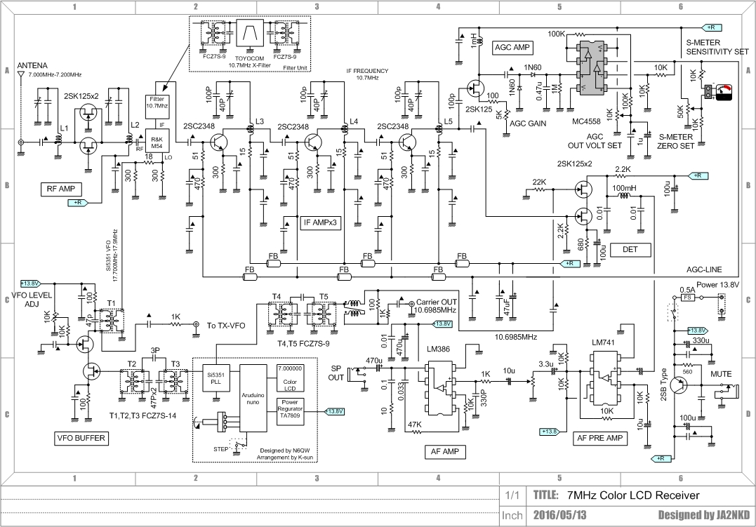
Ryuu's blogs are here : http://ja2nkd.blog.so-net.ne.jp/ and here: http://ja2nkd.blogspot.jp/ They are in Japanese. Google Chrome does a poor job at translating them, but you can get the gist. In any case the pictures are great and the schematics are understandable by all of us. Thanks Ryuu!
Grayson Evans was at Dayton. Scheduling problems prevented him from being interviewed by ace correspondent Bob Crane, but Grayson was kind enough to e-mail us the essence of his presentation. And it is really wonderful. He brings the advantages of the Manhattan construction technique (fast prototyping, all components on the same side of the board, easy modification) to the world of tubes (aka valves or, as Grayson prefers, thermatrons). We also see in Grayson's work an admirable willingness to bridge the digital-analog design, to bring into his rigs the best of the old and the new. Thanks Grayson!
Grayson writes:
An Evolution of Thermatron Homebrew Techniques
For a long time I have been trying to develop some techniques to prototype Thermatron projects as easily as the typical “Manhattan style” solid-state construction. Thermatron projects you see now-a-days still use the traditional technique of mangling aluminum-drilling and mounting everything to a “bud” style chassis. This just takes too much time and my projects always look disappointing.
Fortunately, around two years ago, Rex Harper, W1REX, came to the rescue after hearing an earlier talk of mine and developed a set of thermatron socket pads. The MeTubes panel from QRPme consists of 10 prototype pads for thermatron sockets. The panel has v-scores for breaking the panel into single tube pads. The panel has pads for mini 7 & 9s, octal, compactrons and acorns. Awesome.
The best sockets to use with the pads are PCB style. These provide a large pin area to bend out and solder to the pad (see photos).
I pre-mount a dozen or so of the 7-pin and 9-pin sockets on MeTube pads so I have them ready to go when prototyping. The “crude” example below shows and 7 and 9-pin socket on one of my prototypes. I think this was a microphone amp for my AM transmitter. Pardon the mess.
The nice thing about the pads is that they provide plenty of room to tac solder lots of parts to a single pin–easy to add or remove parts. This is a lot easier than using the traditional tube socket pin.
Prototyping thermatrons in this way is FAST. No more punching out holes to hold thermatron sockets in aluminum chassis!
But it is still nice to be able to have the thermatron on the “top” of the board and the components on the “bottom” of the board. To do this and still use the MeTube pads, the thermatron has to be mounted on the other side. I did this by mounting the socket through the MeTube pad. This requires making a hole in the center of the pad to pass the socket through and then soldering the pins in the usual way. This is way easier with PC mount thermatron sockets and make a very nice installation.
This technique has some great advantages over using the traditional socket with pins. The pad has a lot more room to mount components to each pin. Normal thermatron socket pins are difficult to attach more than two wires and it’s a bit more difficult to get a good solder connection. The pads are easy to solder to and allow components to be easily attached in any direction since the “socket” is now flat.
It is also easy to attach the socket/pad to a copper clad board. The same hole must be made in the copper clad board to pass the top of the socket through, then the pad is superglued to the board in the regular way.
This is another example of “right side up” thermatron mounting on a prototype test board for crystal filters. I mounted a small “plug board” (not sure what you call these things) in the center to allow me to easily swap filter components. Notice the acorn thermatron soldered direct to the pad. The board works great, the filter design sucked. I gave up. Maybe too much distributed C.
I used this technique, combined with Roger Fell’s idea of using inverted aluminum chassis, to build my latest project, a QRP AM/CW transmitter. I’ve been wanting to try out a few new ideas and this seemed like a good project to try them on. I also wanted to build the transmitter in modular “blocks”, interconnected in a similar way to Rogers. It worked pretty good although I am still trying to get the thing to work right. Even new construction techniques can’t cure my screwups. BTW, the ANALOG VFO is ROCK SOLID. +/- 10 Hz over 30 min. Even I was impressed. The Hartley oscillator is the best circuit for thermatron circuits by far.
I’ll send an update when I get it fully working on AM and CW.
Jun JH8SST made this nice video about his version of Pete Juliano's Simpleceiver. I like the approach of putting the stages on separate boards, but perhaps Jun could have made things easier by using Manhattan-style construction on those boards. And of course I like the breadboard-style aluminum sheet. FB Jun. Jun writes:
I've built a simpleceiver, which is a modified version. My first main board didn't work because of several problems, and that's why I decided to divide the board into several separated PCB's with some circuit modifications.
RF and Mixer stages are original, but I employed an 8pole 9MHz ladder Xtal filter. The J310 X 2 is used in IF amplifiers, but load resonant circuit is modified to use a type 10K coil form and a ceramic capacitor.
J310 product detector is original and built on a tiny PCB, as shown in attached photo and YouTube Video.
This modified Simpleceiver has high sensitivity and more than enough gain. I needed to reduce RF/IF gain to eliminate product detector distortion caused by stronger signals.
This simpleceiver works really nicely.
I'm going to re-modify it to make it as original as possible.
The block diagram is: J310X2 RF-DBM-9MHz 8 pole X'tal Filter-J310X2 IF-J310X2 IF-J310 product detector-AF μA741-AF LM380 with NFB.
I'm going to re-modify it as: J310X2 RF-DBM-J310X2 IF-12MHz 4 pole X'tal Filter-J310X2 IF-J310 product detector-AF μA741-AF LM380 with NFB.
I'm also going to add an AGC system using a modified W1FB AGC circuit.
Much to the consternation of Pete "Digi" Juliano, I have been working on analog LC VFOs for simple superhet receivers. As described in earlier posts, I recently converted an old Barebones CW superhet to 40 meter SSB. At first, the VFO (2 -2.3 MHz) was not stable enough -- it would slowly drift in frequency. ("We have a solution for that," chuckled Pete.) My first effort at stabilization involved replacing the toroidal coil. The material in the core is sensitive to temperature changes and this can lead to instability. I found my traditional cardboard tube from a coat hanger, and made a coil of the needed inductance (you can see it in the pictures). This yielded some improvement in stability, but it was still drifting. Next I tried taking out all the silver mica and disc ceramic caps in the LC circuit of the oscillator and replacing them with NP0 ceramic caps. The feedback caps are in the box below the tuning cap, but you can see some of the little NP0s on the outside of the box, connected to a rotary switch. This serves as the equivalent of variable "Bandset" variable cap, with the tuning cap serving as the "Bandspread." I have seven switch positions, each covering about 40 KHz (with some overlap). This gives me all of the phone band and the bottom 30 kHz of the CW band. Switching to NP0 caps really did the trick. The receiver is now very stable. When I told Farhan about my VFO woes, he mentioned that he'd had very good stability results with surface mount caps. I wonder if this success has more to do with those caps being NP0 than with their surface mount configuration. Here is a good description of NP0:
NP0 Ceramic Capacitors are single-layer ceramic capacitors made from a mixture of titanates.
A NP0 ceramic capcitor is an ultrastable or temperature compensating capacitor. It is one of the most highly stable capacitors. It has very predictable temperature coefficients (TCs) and, in general, does not age with time. NP0 stands for negative-positive 0 ppm/°C, meaning that for negative or positive shifts in temperature, the capacitance changes 0 part per million, meaning that it has a flat response across a wide range of temperatures; the capacitance of the NP0 capacitor stays constant (at the same value) despite variations in temperature. From: http://www.learningaboutelectronics.com/Articles/What-is-a-NPO-ceramic-capacitor
But I think it is a stretch to claim that these marvelous caps do not "age with time!" That would be a really astounding property of the titanium dielectric. That would be a Negative-Positive Zero FLUX capacitor, right?
My wife and I went to see this flick about the mathematician Srinivasa Ramanujan. It was filmed at Trinity College, Cambridge -- if you look at the dedication to "SolderSmoke -- Global Adventures in Wireless Electronics" you will see a picture of my kids at Cambridge. Alas, that picture was taken at Kings College, not Trinity; nonetheless, the Cambridge connection got us interested. Then there was the Indian aspect of the story, which is very intriguing. There was also the "amateur makes good" angle that all of us should, I think, find very encouraging.
The movie did not disappoint. We really liked it. The presentation of the cultural clash was very well done. Elisa told me that as she watched Ramanujan struggle with England, she found herself wanting to tell him, "You are just going through culture shock. Be patient! I've been through this many times!" They included just enough math to give the viewer a sense of what Ramanujan was working on. I got a real kick out of one scene in which old Professor Hardy, seeking to motivate young Ramanujan, took him into the Wren Library and showed him the manuscript of Newton's Principia. I had seen the same manuscript in the library of the Royal Society in London -- they had take it out on the occasion of the visit to the library of Stephen Hawking and NASA Director Mike Griffin. They also had on the table the reflecting telescope that Newton himself had made. That was quite a day.
Great movie. I give it the coveted rating of five soldering irons.
I sat in the shack this morning with a cup of coffee, mesmerized by the things Pete was saying. I actually took notes. Some highlights:
-- In describing his zeal to avoid the use of store-bought components, Pete acknowledged that there are limits to this. But then he revealed that his limits are different than those of even the most fundamentalist of homebrew fundamentalists: "Well, I'm not going to mine my own copper." Don't worry Pete -- no one will call you an appliance operator if you use store bought wire.
-- On the same subject, when describing his homebrew diodes for crystal radios, Eric asked Pete why he didn't just go out and buy a Germanium Diode. "That would be cheating," replied Pete. Indeed.


