Podcasting since 2005! Listen to Latest SolderSmoke

Saturday, September 16, 2023

"The Art of Electronics" by Horowitz and Hill (First in a Series of Blog Posts on this Great Book)

Paul Horowitz

Oh man, this book is so good.  You really just need to buy it now.  I put it in the Amazon link to the right.

OVER HERE >>>>>>>>>>>>>>>>>>>>>>>>>>>>>>>>>>>

The Imsai guy reminded me of this book, and pointed out that earlier editions are more reasonably priced, so I got the second edition (looks like 1980, reprinted many times through 1988).   Dean KK4DAS got one too (I think he also got the second edition).   

Lest there be any doubt that this book is for us, first let me point to the pictures of Paul Horowitz and Winfield Hill.  https://artofelectronics.net/about/

Winfield Hill 

Just from the pictures, you can tell that these guys have THE KNACK.  And -- get this -- THEY ARE BOTH PROFESSORS AT HARVARD.  Wow. 

Their web page explains where the book came from: 


Dean KK4DAS and I have already started sharing quotes from the book: 

Referring to other books, H and H  write:  "Much of the favorite pedagogy of beginning textbooks is quite unnecessary, and, in fact, is not used by practicing engineers, while useful circuitry and analysis lies hidden in application notes, engineering journals, and hard-to-get data books." 

"Thus, the treatment of this book reflect our philosophy that electronics, as currently practiced, is basically a simple art, a combination of some basic laws, rules of thumb, and a large bag of tricks. For these reasons we have omitted entirely the usual discussion of solid state physics,  the h-parameter model of transistors, and complicated network theory, and reduced to the bare minimum the mention of load lines and the s-plane.  The treatment is largely non-mathematical, with strong encouragement of circuit brainstorming, with mental (or, at most, back-of-the-envelope) calculation of circuit values and performance." 

Stay tuned.  There is a lot more coming about this wonderful book. 

Friday, September 15, 2023

HB2HB -- A Contact with Denny VU2DGR (video)

At first I didn't realize it was Denny.  On September 11, 2023 at about 2330Z I had walked back into the shack after dinner.  I think DX spots showed an Indian station on 20 meter SSB.  Without realizing who it was, I tuned him in on my Mythbuster rig, heard the other station sign off, and quickly threw in my call.  Denny came back to me right away, and I think both of us then realized that we recognized the call of the other station. Wow, it was Denny, VU2DGR, the Wizard of Kerala!   At the time of the QSO, I didn't have my phone with me; after we spoke, I went to get it,  so the video above captures part of Denny's subsequent contact. (You can also at one point hear Guapo barking.) 

Denny has been running a wonderful station that combines SDR gear with and HDR tube type amplifier and a homebrew Moxon.  

Here is Denny's station. The transceiver is a RadioBerry.  the amplifier and power supply are on the other table.  


Here is the homebrew tube-type amplifier.  This is the part of the station that really puts the HB in HB2HB! That's the power supply on the left and the amplifier itself on the right: 


That amplifier has three 807s in it, with a 6L6GC: 


Here's a video on the RadioBerry transceiver. 


Finally, here is Denny's magnificent homebrew 20 meter Moxon: 


Thanks Denny! 

Thursday, September 14, 2023

Building Nixie Tubes for a Hiroshima Project


Thanks to Bob Scott KD4EBM for alerting me to this wonderful video.  It seems especially timely, given the recent release of the Oppenheimer movie.  

I posted back in 2000 about Dalibor Farny and the Nixie tubes he makes in a castle in the Czech Republic:

In this more recent video (above) Dalibor describes a very cool and very challenging Nixie tube project:  A museum in Hiroshima Japan was presenting an art project designed by a Chilean artist.  The display needed a lot of large, custom-made Nixie tubes, some of which would display Japanese language characters.  So: Museum in Japan, Chilean artist, Nixe maker in the Czech Republic.  There are big geographic challenges before you even get to the technical challenges.

Dalibor does a great job in describing all of the challenges that they faced.  The technical stuff will be especially interesting to SolderSmoke listeners.  His description of the evolution of his Czech workshop fits very well with our "other kinds of workshops" theme. 

The video is really worth watching.  Check it out (above).  The ending is quite moving. 

Thanks again to Bob Scott.   Congratulations to Dalibor, his crew, and to all those involved in this Hiroshima museum project. 

Tuesday, September 12, 2023

BEZOS BUCKS ARE BACK!

With the help of several loyal SolderSmoke listeners, we finally cracked the code and figured out how to put the new Amazon Ads on the blog.  You can see it on the right side of this page. 

Right over here >>>>>>>>>>>>>>>>>>>>>>>>>

You don't have to buy whatever we are advertising.  Just click on the SHOP NOW sign and begin your Amazon shopping there.  In this way SolderSmoke will get a small commission on any purchase you make (within 24 hours of your initial click on the SHOP NOW icon). 


Friday, September 8, 2023

Why Building for 10 Meters is Harder than Building for Lower Frequencies


Recently my trusty CCI EB63A .1kW amplifier has been in rebellion.  On 10 meters, it now often insists on being an oscillator.   It calms down nicely on 20 meters.  But on 10, it has been a rebellious beast.  

Why is this?  Why would an amplifier that is well behaved and stable on 20 meters behave so badly on 10 meters?    

I used LTSpice to explore the problem.  

I looked at two ordinary wires.  I gave them each a value of .003 uH.  Very low.  Then I joined them together in a transformer.  I put a 1 volt signal into the primary and looked (in LTSpice) at how much of a signal appeared in the secondary.  First, the result on 14 MHz.  About 250 mV appears on the secondary. 


Now consider what happens at 28 MHz.  Nothing else in the circuit changes.   Just the frequency.


Here we get about 450 mV.  A lot more.   

Realize that my little EB63A amp has lots of wires in it, most of which are ready to serve as primary or secondaries in circuits like this.  Increasing the frequency makes it more likely that a ginal will jump to someplace that it is not supposed to be.  Output will couple to input and the Barkhausen criteria will be met. The amplifier will become an oscillator.   

Of course, something similar happens with capacitive coupling.  Same story:  the higher the frequency, the harder it is to keep the amplifier stable. 

Don't worry:  Improved shielding is saving the day.  The amplifier is now stable on 10.   More about this in the next podcast... 

Monday, September 4, 2023

SolderSmoke Podcast #248 -- Back from the Summer -- Spurs and Filters, S-meters, 6BA6 mania, Shirtpocket rigs, MAILBAG

The PsssT Kit, coming soon from Mostly DIY RF

SolderSmoke Podcast #248 is available for download: 

Audio: http://soldersmoke.com/soldersmoke248.mp3

Video: (800) SolderSmoke Podcast #238 -- Spurs and Filters, S-meters, 6BA6 mania, Shirt-pocket rigs, Mailbag - YouTube


Travelogue:  Trip to the Dominican Republic 3-9 August.  Thinking about the M0NTV video on mixers...  

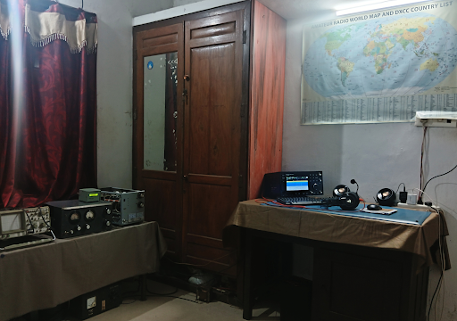
Solder Smoke Shack South is almost done.   I am thinking about workbenches, operating tables and antennas.  How high should an electronics workbench be?   Table height?  Or workbench (woodwork) height?  

My son and I went to see "Oppenheimer"  Trinity test scene very cool.  They wanted to see if the gadget would work! 

Is the SolderSmoke blog completely archived on the WayBack Machine?  Please check and let me know.  Thanks. 

Bill's Bench: 

-- I've been working a lot of DX with the homebrew rigs:  Indonesia, Australia, Japan, Hawaii.  Lots of fun.  15 meters has been especially good. But the rigs still need work: 

-- M0NTV's video got me to put TinySA to work.  I found that output from dual banders could be improved.  Spurs and harmonics. Yuck.  I need more TinySA -- ordered the TinySA Ultra. 

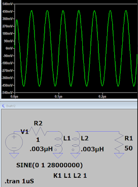
-- Allison KB1GMX helped a lot.  EB63A amp was unstable, especially on 10 meters.  Higher frequencies are harder!  Tightened up shielding, negative feedback, and bypassing.  This all helped, but I found that I needed to take the higher frequency LP filters out of the amplifier box.  W3NQN filters are better, with steeper skirts and better 2nd harmonic rejections. NanoVNA proving very useful. https://www.gqrp.com/Datasheet_W3NQN.pdf

-- Also worked on the Bandpass filters for these rigs.  Farhan's comments on skirts of different filter configurations.  Some are "LSB" filters (with steeper skirt at the highest freq) and some are "USB" filters (with the steeper skirt at the lower frequency)  See diagrams on the blog page. So I built USB new filters for 12 meters and for 10 meters. 


-- Danger that my unshielded wooden box rigs might be inviting feedback.  So I shielded the 1510 rig with copper guitar amp tape (conductive adhesive).  Good stuff.  

-- Phase Noise rears its ugly head again.  See blog posts. 

----------------------

SHAMELESS COMMERCE DIVISION:  

Mostly DIY RF getting ready to release PsssT kits.  Target date:  December 18, 2023 (E Howard Armstrong's birthday).  https://mostlydiyrf.com/

Amazon Search box seems to have died.  I can't get it back.  Can anyone tell me what happened?  (There seems to be "explanations" from Amazon about this, but they are written in a strange language that I cannot follow.)  Something similar happened with the Google Ads on this blog page.  Apparently you can't have ads both on YouTube and blogger.  

But hey, there is Patreon for those who want to support the podcast and blog. 

-------------------------

Pete's Bench

An S-meter for Bill? 

6BA6 Mania! 

QRP SSB with 6BA6

Shirtpocket rig re-build

Mailbag: 

Walter KA4KXX has a great article about homebrewing in the September 2023 QCWA Journal.  

 Steve KC1QAY -- Has joined the CBLA.  I sent him a 3579 crystal.  He built a MMM and experienced JOO.  And Allison KB1GMX is in his local radio club.  TRGHS. 

Ajay VU2TGG in Pune, India -- launching a high school receiver effort. 

Denny VU2DGR The Wizard of Kerala: https://soldersmoke.blogspot.com/2023/08/the-wizard-of-kerala-india-denny-vu2dgr.html

Joe VK4BYER working with kids a remote Australian community.  FB. 

Todd K7ZF -- Wants to get into homebrewing. Advised him to start small. 

Dean KK4DAS:  Fixing Hallicrafters Worldwide RX. Ciudad Trujillo!  Got question from Mark in the VWS Makers Group:  HOW DOES Michigan Mighty Mite REALLY Work.  See blog. 

Trevor Woods -- Info on Super Islander Mark IV made in Cuba from old CFL bulbs.  FB. 

Bob KD4EBM sent me some great stuff:  Sony SW receiver,  QCX Mini.  Made a CW contact with the QCX.  Felt virtuous -- it is going to the DR.  Thanks Bob. 

Peter KD2OMV:    One of the guys I worked with the ET-2 transceiver.  Great to hear from him. 

Armand WA1UQO   Richmond area radio museum? https://www.youtube.com/watch?v=BSCmljje1p8

Mike WN2A -- Sent me a great care package with lots of toroids.  A lifetime supply!  Thanks Mike!

Nate KA1MUQ got his Doug DeMaw receiver going after 38 years!  FB.  Been there, done that! 

Tony: G4WIF Liked Valveman video about Gerald Wells.  He visited him! https://soldersmoke.blogspot.com/2023/08/valveman-story-of-gerald-wells.html 

Dean KL7MA  Bill talked to him on 15 SSB.  He had worked Wes W7ZOI!  FB! 

Monday, August 28, 2023

But How Does the Michigan Mighty Mite REALLY Work?

Dean KK4DAS and I were talking to Mark, a new homebrewer.  After we sang the praises of the Michigan Mighty Mite,  Mark asked us a good question:  How does it really work? 

I guess the starting point for analysis is the Barkhausen criteria (that Pete N6QW taught us):  essentially you need enough feedback to overcome losses in the circuit, and this feedback has to be in phase with the signal at the input.  The MMM is clearly oscillating, so the question becomes, "How does this very simple circuit meet the Barkhausen criteria?" 

Here goes: 

Even though it is a very simple circuit, it is worthwhile to separate out the things that it has to do: 

1) It needs to set the AMOUNT of feedback.    This is done by the tap on L1.  Too low down on the coil, and it is too close to ground through the .05 uF capacitor (not enough feedback).  Too high on the coil and you get too much feedback.  This is like an inductive voltage divider. 

2)  It needs to make sure that this feedback is in phase with the input signal. Positive feedback. Q1 is an inverting amplifier.  So it supplies 180 degrees of phase shift. As the signal at the base goes more positive, the signal at the collector goes more negative, and vice versa.  But we need an additional 180 degree shift to bring the output signal in phase with the input signal.  Here is the key:   The crystal provides the other 180 degrees of phase shift.  See


I tested this:  A 3.579 MHz crystal does provide the needed phase shift:  It introduces a shift of about 190 degrees.  Check out this very cool picture. The two scope probes are looking at the input and the output of the 3.579 MHz crystal with 3.580 MHz frequency coming from my HP sig gen. 

Click on the picture for a better view.

3) It needs to filter out other signals -- the 365 pf variable cap resonates with L1 at around 3.579 MHz.  This results in maximum circulating current through L1 at this frequency. 

4) It needs to match impedance to the antenna.  L2 wound over L1 forms the secondary of a transformer and efficiently moves the energy from the MMM to the antenna.  Think about the gears on your bike. 

The 10k resistor biases the base of the transistor, keeping it on.   The 27  ohm resistors limits the current through the transistor, preventing it from burning up. Note:  the 27 and 10k resistors should NOT be connected directly to each other.  There is no dot in the schematic. This causes some confusion among builders. 

The .05 uF capacitor does two things:   It grounds the L1/365pf tank circuit for RF (but not for DC).   It is less than 1 ohm at 3.579 MHz.   And it helps reduce (smooth out) key clicks (very sudden on-off changes in the oscillation). 

Wednesday, August 23, 2023

Homebrew Transistors


Hang your heads in shame, my friends.  This dude is getting ready to homebrew his own transistors.  None of that store-bought stuff for him.  He is a few steps away from breaking free of the GLOBAL TRANSISTOR CARTEL that has been abusing us so-called "homebrewers" for so many years.   This guy really puts the home in homebrew. 

Plus he has a seriously cool shop enabling him to do some excellent metal and chemical work.  

Thanks to Hackaday for alerting us to this. 

Sunday, August 20, 2023

15 Meter Homebrew SSB Rig As Heard in Mexico City

 19 August 2023. Ralph XE1RK recorded part of our QSO and played it back to me. Thanks Ralph!

I was running about 75 watts to a hex beam aimed Southwest.

Saturday, August 19, 2023

Valveman -- The Story of Gerald Wells


Don't be deterred by the annoying test patterns at the start of this video.  Just skip past them.  The rest of the video is quite good.  Or you could just click on this link and avoid the first 83 seconds of test pattern:  https://youtu.be/Y8w6iwaAGJ4?t=83

Gerald Wells has been mentioned on this blog before, but I don't think we've ever presented the full documentary on this fellow.  Here it is.  Gerry is clearly one of us: a radio fiend, obsessed (as he admitted!) with wireless, a victim of THE KNACK.   

George WB5OYP of the Vienna Wireless Society got to meet Gerald Wells and visit his museum. George alerted me to this video.  Tony G4WIF also was able to visit Gerry and his museum. 

The documentary is full of interesting stuff, and is, in itself, a Knack Story.  Wells mentions the Crippens murder so well described by Eric Larson in "Thunderstruck."  It was this crime that brought radio to the center of public attention.  

More Ancient Technology Keeping Space Missions Alive


 https://www.bbc.com/future/article/20230815-the-ancient-tech-keeping-space-missions-alive

Three cheers for software.  Really. 


Wednesday, August 16, 2023

Working Indonesia and Chile with new 15-10 Homebrew Transceiver


Conditions were good this morning, and the Radio Gods continue to favor homebrew rigs.  I got on 15 meters SSB with the new 15-10 dual bander and quickly worked YH0AD in Jakarta (about 10,000 miles).  A few minutes later I talked to YB2MVD; he was a bit further east on Java.  I shot a video of the QSO with YB2MVD.  He said I was 59.  

I then switched to 10 meter SSB (same rig) and worked CE4PS in Chile (5,000 miles).   

TRGHS. 

The antenna for all these contacts was my K4KIO Hex Beam.  I was running about 75 watts from the .1kW CCI amplifier. 


Tuesday, August 15, 2023

The Wizard of Kerala (India) -- Denny VU2DGR -- SDR and HDR

 
His signal was just booming in on 20 meter SSB yesterday evening.  It was one of the strongest signals I've heard from India.  I wasn't able to get through the pileup, but I heard mention of a homebrew station at his end...  Sure enough a look at his QRZ.com site shows that a LOT of solder has been melted in his shack.  Both SDR and HDR stuff.  Tube projects including an 807 amplifier made from "components collected from the scrapyard." And a homebrew 20 meter Moxon.  Check it out: 


FB Denny!

Kerala is on the southwest tip of India.  It is something of a hotbed of technological innovation.  My only Indian contact using my current series of homebrew dual-banders was with VU3TPW -- Renju is also in Kerala. 

Monday, August 14, 2023

You have heard of the International Geophysical Year (IGY). But have you heard of the IQSY?


International Quiet Sun Year.  1964-1965.  Yes, that was a thing.  

Tuesday, August 1, 2023

Voyager, Canopus, JPL, and 74xx Logic Chips from the early 1970s


"So somewhere out there in interstellar space beyond the boundary of the Solar System is a card frame full of 74 logic that’s been quietly keeping an eye on a star since the early 1970s, and the engineers from those far-off days at JPL are about to save the bacon of the current generation at NASA with their work. We hope that there are some old guys in Pasadena right now with a spring in their step."

https://hackaday.com/2023/07/31/just-how-is-voyager-2-going-to-sort-out-its-dish-then/


Sunday, July 30, 2023

Understanding Maxwell's Equations (video)


And you should also look at the accompanying web site: 

Writing about the equations, the author notes, "They are formidable to look at - so complicated that most electrical engineers and physicists don't even really know what they mean.  This leads to the reason for this website - an intuitive tutorial of Maxwell's Equations. I will avoid if at all possible the mathematical difficulties that arise, and instead describe what the equations mean. And don't be afraid - the math is so complicated that those who do understand complex vector calculus still cannot apply Maxwell's Equations in anything but the simplest scenarios. For this reason, intuitive knowledge of Maxwell's Equations is far superior than mathematical manipulation-based knowledge. To understand the world, you must understand what equations mean, and not just know mathematical constructs. I believe the accepted methods of teaching electromagnetics and Maxwell's Equations do not produce understanding. And with that, let's say something about these equations.

Thanks to Armand WA1UQO for sending me the wonderful book about Faraday and Maxwell that put me -- once again -- on the path toward a deeper understanding of their work.  

Friday, July 28, 2023

Phase Noise and the Radio Amateur

A weak signal disappears in the phase noise of the stronger signal.

The March 1988 QST provides a relatively clear explanation of what phase noise really is:

Highlights: 

Phase noise is an undesired variation in the phase of the signal. In this case, an oscilloscope shows that the time between zero crossings of the signal varies over time when compared to the zero crossings of an ideal sine wave. An exaggerated example of phase noise is shown above.

Phase noise on an oscillator signal has exactly the same effect as frequency modulating the oscillator with noise.

Whenever a carrier is passed through a mixer, the phase noise of the oscillator driving that mixer is added to the carrier.

Phase noise on a transmitted signal causes effects identical to phase noise generated in a receiver.

Any signal that reaches a mixer in the receiver is modulated by the phase noise in the local oscillator driving that mixer. As such, the signal appears to have at least as much phase noise as the local oscillator. Thus, sufficiently strong signals off the receiving frequency can degrade receiver sensitivity by raising the noise floor at the receiving frequency. Receiver dynamic range is reduced as the noise floor rises.

With a frequency-shift-keyed or- a phase-shift-keyed signal, the close-in phase noise limits the maximum bit error rate that the system can achieve. Both of these effects can be quantified once the communications system is defined. With an SSB voice signal, the effects are much harder to predict, but excessive phase noise does degrade SSB signal intelligibility to some extent.

--------------------------------
Receiver guru Rob Sherwood provides some very useful historical background on his web site:

http://www.sherweng.com/documents/TermsExplainedSherwoodTableofReceiverPerformance-RevF.pdf

Phase Noise: Old radios (Collins, Drake, Hammarlund, National) used a VFO or PTO and crystal oscillators to tune the bands. Any noise in the local oscillator (LO) chain was minimal. When synthesized radios came along in the 70s, the LO had noise on it. It is caused by phase jitter in the circuit, and puts significant noise sidebands on the LO. This can mix with a strong signal outside the passband of the radio and put noise on top of the weak signal you are trying to copy. This is a significant problem in some cases: You have a neighboring ham close by, during Field Day when there are multiple transmitters at the same site, and certainly in a multi-multi contest station. You would like the number to be better that 130 dBc / Hz at 10 kHz. A non-synthesized radio, such as a Drake or Collins, has so little local oscillator noise the measurements were made closer-in between 2 and 5 kHz.   

-------------------------------------
Experimental Methods in RF Design (EMRFD) has this to say about phase noise:

"The local oscillator is a critical part of any communications system. Modern transceiver performance is often compromised by LO systems that suffer from excess phase noise, effectively limiting the receiver dynamic range. While quiet oscillators, those with low phase noise, can be built using traditional methods, these circuits often lack the thermal stability of a synthesizer.... Frequency synthesis is not, however, the answer to all the LO problems presented to the experimenter.  Some PLL synthesizers are burdened by excessive phase noise. Those using DDS, while quieter, emit spurious outputs, often in profusion.  Both use an excess of digital circuitry that can often corrupt a receiver environment."  page 4.1
   
"At first glance, phase noise sounds like an esoteric detail that probably has little impact on practical communications.  This is generally true." page 4.12 

--------------------------------------

Hans Summers G0UPL analyzed and measured the phase noise of the Si5351a chip: 

http://qrp-labs.com/qcxp/phasenoise.html

------------------------------------

DC4KU appears to be using the crystal filter method used by Hans: 

https://dc4ku.darc.de/Transmitter-Sideband-Noise_DC4KU.pdf

------------------------------------

Martien PA3AKE has done a lot of great work on this topic.  See: 

https://martein.home.xs4all.nl/pa3ake/hmode/dds_pmnoise_intro.html

-----------------------------------

Dean KK4DAS commented on the phase noise video of the IMSAI guy: 

Watching the video I was reminded of Segal's law roughly paraphrased as follows.:

A man with one spectrum analyzer knows his phase noise. A man with two is unsure.

Sunday, July 23, 2023

First Contacts with 15-10 Rig -- Two Atlantic Crossings


I was just testing it, working (as usual at this stage) on final amplifier stability.   Then I heard ON5WO calling CQ.   I could not resist.  I worked him, but had to use a test lead to manually key the .1 kW amplifier.  Minutes later I worked OH6RM.  He very diplomatically said that I had "highly unusual audio."  This was probably due to earlier efforts to shift the carrier oscillator to improve carrier suppression. (I will fix this.)  

I will continue to work on the rig; It should look a bit better when I am done.  But hey, it works!  It has already crossed the Atlantic. Twice!  

Tuesday, July 18, 2023

"Onda Corta" ("Shortwave") -- A Short Film about Ham Radio in Venezuela (Please ID the Boatanchors!)


I have it cued up to 9:43 -- at that point Ramon is in his ham shack.  
Lots of good stuff in there! 

Please ID the rigs/parts you see and list them in the comments below. 

This version has subtitles in English.  I like it -- a nice story.  And the whole film is only about 15 minutes. 

Monday, July 17, 2023

Going Down the Phase Noise Rabbit Hole with the IMSAI Guy (VIDEO) -- Is there a better way?


Chimera:  2.
a thing that is hoped or wished for but in fact is illusory or impossible to achieve.
(from the Oxford English Language Dictionary). 

Phase Noise.  We know what it is, but how do you measure it?  Pete N6QW and I went through this back when people were casting phase noise aspersions at (Pete's!) beloved Si5351.   More recently phase noise hate  has been focused on (my?) beloved Franklin oscillator.  When I asked a very technically proficient and guy at the VWS club if he could measure phase noise, I was surprised when he honestly said that he could not. 

And now we have the IMSAI guy saying, essentially, the same thing.  Wow, if the VWS guy and the IMSAI guy -- with all the spectrum analyzers at their disposal -- have trouble measuring phase noise, what hope do we ordinary hams have?  I mean, at best most of us have just an oscilloscope, a NanoVNA,  and a TinySA.  

Look, I know that phase noise is real and in certain circumstances, it is important.   But sometimes I suspect that its measurement is also a bit of a technical chimera:  If,  for whatever reason,  there is a circuit that you don't like, you can claim that the phase noise of that circuit is bad.  Or horrible. I think we see this sometimes with the Franklin oscillator.  Very few hams will be able to measure it and dispute the assertion that the phase noise is bad.    

For a perhaps painful walk down SoldeSmoke's "Phase Noise Memory Lane"  go here: 

Thanks to the IMSAI guy for a great video.   But let me ask:   Is there a better, simpler way to measure phase noise?  One that will avoid chimerical results and that could be used by hams with sort of standard ('scope, sig gen, NanoVNA, TinySA) test gear? 

Sunday, July 16, 2023

The Super Islander Mark IV -- A Cuban DSB Transceiver Made From CFL Lightbulb Parts


Trevor Woods also sent us this report from Arnie Coro.  It is not clear to me what difference (if any) there is between the Super Islander Mark IV and the Jaguey Five (described yesterday).  But the bit about using parts from old CFL bulbs is interesting.  This was something championed by Michael Rainey AA1TJ several years ago.  See: https://soldersmoke.blogspot.com/2009/01/soldersmoke-98.html  
and:
https://www.qsotoday.com/transcripts/aa1tj

April 2010:

Today, I will be answering a question sent by listener Bruno from Croatia... Bruno picks up our English language programs via Internet, but he is now also listening on short wave too. He sent a nice e-mail message asking me about the latest version of the Super Islander amateur radio transceiver, because he wants to build one.

Well amigo Bruno, the Super Islander Mark IV is now on the air, and results are very encouraging considering that it is a 40 meters band transceiver built using recycled electronic components.

The Mark IV uses a totally different approach to the receiver design, and it adds two solid state audio filters.

Amazing as this may sound, some of the electronic components used to make the Super Islander Mark IV transceiver came from the circuit boards of broken or damaged Compact Fluorescent Light Bulbs... and that means that there is virtually an endless supply of those parts.

Here is now amigo Bruno, and amigos listening to the program at this moment, a brief description of the Super Islander's Mark IV receiver module.

It starts with a simple resistive signal attenuator that feeds a dual tuned bandpass input filter.

The filter has a limited bandwidth , chosen so as to limit response to out of band signals... The filter is followed by a cascode transistor radio frequency amplifier stage, that feeds a broadband four diodes product detector.

Low level audio from the product detector goes to the audio filtering and amplifying module, made with discrete transistors, of which several of them are also recycled from the Compact Fluorescent Light Bulbs circuit boards...

This version of the Super Islander, the Mark IV , is radically different from any previous ones, as we have now switched over to a totally low cost solid state design , that can be easily reproduced because it uses very common electronic components and straightforward , easy to adjust circuits.

In our upcoming mid week edition I will describe the VFO, or variable frequency oscillator and the transmitter module of this unique low cost amateur radio transceiver, the Super Islander Mark IV... about the lowest possible cost transceiver that will make possible regular two way ham radio contacts on the 40 meters band using either voice or radiotelegraphy modes.

Saturday, July 15, 2023

The Jaguey Five -- The Solid State Cuban DSB Rig -- Circuit Description

Obviously we need a picture of a Jaguey transceiver. 
"Made in Jaguey Grande" 

Trevor Woods found this report from Arnie Coro (SK) CO2KK: 

February 2009: 

Here is now item three in detail: It was quite a long time ago, when I heard about a nice project sponsored by IARU, the International Amateur Radio Union, that was promoting the design of a kit, a simple single band transceiver kit that could be sent in a small air mail parcel to radio clubs in Third World nations which could then deliver them to would-be radio amateurs, and help them build and align the radios... But, unfortunately I lost track of the project, and as many of our listeners may realize there is still a great need of such a project... Past efforts along this line have had some problems, among them the mistaken approach of using of very sophisticated electronic components that in case of a breakdown would be impossible to replace locally; and also, all attempts seemed to try to make the transceiver an ultra- or near-ultra-miniature radio, something that won't help at all with beginners...

So, when I recenlty received an e-mail from Canada, asking what I thought about reviving this great idea, our Canadian amigo asked what we had already done here in Cuba, with our JAGUEY double side band plus CW 10 watt transceiver that went up to REVISION NUMBER 5. , This was the last upgrade, done about three or four years ago, and we named it the Jaguey FIVE, as it generates 5 watts of CW... The Jaguey FIVE was a low parts count, not miniature, easy to build single band transceiver that used readily available components, instead of sophisticated state of the art parts...

In order to please the friend who wrote about this topic, here is a brief, on the air, description of our Jaguey FIVE and by the way, Jaguey is the name of a town, actually it is Jaguey Grande, or big Jaguey, and the Jaguey is a beautiful tropical tree... The original Jaguey transceiver originated in that Matanzas province town in 1982,

The receiver part starts with a simple yet effective RF attenuator, then it feeds a bandpass
filter made of two tuned circuits... we use shielded IF transformers from old TV sets 4.5 megaHertz audio chains... A simple bipolar NPN small signal transistor grounded base amplifier feeds a homebrew double balanced mixer... and we "discovered" quote, unquote, that the antenna balun transformers used in TV sets, the 300 to 75 ohms baluns, had a ferrite core with two holes that makes a wonderful broadband transformer for the double balanced mixer...

We use computer diodes removed from defunct ISA old computer cards and motherboards and developed a very simple test jig to match the diodes... The double balanced mixer is fed on the other port from a simple three transistor oscillator, of which we have two versions, one using three NPN bipolar transistors and the other one using an FET oscillator followed by two bipolars... at the output of the mixer we have AUDIO, as this is a direct conversion receiver, amigos!!!

Now we amplify the audio using discrete components and again we have two versions of audio filters, one with bipolar NPN transistors and the other using a very common operational amplifier IC... The audio power output stage also is available to the builder in two versions, one using discrete components and the other using an integrated circuit audio amplifier that is locally available here in Cuba and produces a booming 2 watts of audio, with a lot of gain and rather low noise! This is the audio IC used by the most popular TV set in use here in Cuba, so we were able to obtain them from the TV repair shops at low cost.

Well, that's why I will describe as a flexible design... again, no attempt is made to make the Jaguey single band amateur transceiver a miniature rig, as miniaturization is definitely not for beginners!!! And following up this description of the receive section of the Jaguey, in our upcoming mid-week edition of Dxers Unlimited, I will describe the transmitter section of the rig,that shares the same variable frequency oscillator with the receiver.... I think that a new more up to date version of the Jaguey transceiver could very well be made available in kit form, with large-sized and easy to assemble circuit boards. The old Version 5 uses three circuit boards, one for the receiver, one for the VFO and one for the transmitter, so the newcomer can assemble just the receiver and start listening to amateur radio communications before having his or her own ham license!!!

You are listening to the weekend edition of Dxers Unlimited coming to you from Havana on the air and on the web at our Dxers Unlimited blog.

----------------------

A video of Jaguey Grande, Cuba: https://www.youtube.com/watch?v=krblz_5o6jU

Earlier posts about the Jaguey on the SolderSmoke blog: https://soldersmoke.blogspot.com/search?q=Jaguey

Tuesday, July 11, 2023

Homebrew in Namibia -- Joe Noci V51JN -- -- The Wizard of Sawkopmund

 
Here at SolderSmoke I like to highlight the homebrew adventures of far-flung radio builders.  Joe V51JN melts solder in an especially exotic location:  on the edge of the Namib desert.   He is in a very interesting place:  https://en.wikipedia.org/wiki/Swakopmund

Here is Joe's QRZ.com page: https://www.qrz.com/db/V51JN

Joe recently posted on the Amateur QRP Radio Facebook group: 

I am not on the air much - here in Swakopmund ( Namibia) we have quite bad RFI from mains borne RF control signals for geysers, pumps, etc and 40M is unuseable, 30M almost usable and 20M sort of useable.. Complaint to CRAN - Our Radio Ministry - achieve nothing...So I do mobile out in the desert in the 4X4 when I can! I enjoy building radios - here are some photos - first is a 5watt 7MHz to 21MHz all band SSB rig - all homebrew, inc crystal filters, etc. PA is a push-pull LDMOS amp, 5W PEP.


Thanks to Doug KB8M for alerting me to this amazing work. 

Monday, July 10, 2023

Martein's Bandpass Filters - PA3AKE

Above you can see the really nice 15 meter filter that I built using data provided by Martein PA3AKE. 

https://martein.home.xs4all.nl/pa3ake/hmode/bpf_all.html 

Before I built Martein's filter, my bandpass had been inadequate.  Looking at the signals coming out of the diode ring mixer in my 15-10 rig, I realized that when I was on 15, there would also be an output on 10.  And vice-versa.  These outputs would have to be knocked down by the bandpass filters.  I had been using simple dual tuned circuit filters. But when I looked at the filter shapes of these filters in NanoVNA, I could see that On 15 the 10 meter signal was only down about 20 db.  And on 10 the 15 MHz output was also down only by about 20 db.  That's not enough.  Take a look: 

Before,  with the dual tuned circuit filter

After with Martein's Filter 21.5 Mhz

AFTER with Martien's filter 21.1 MHz

While the earlier filter had provided only about 20 db of attenuation at 28 MHz, Martein's filter provided at least 68 db of attenuation.  That is really nice.  And the passband is nearly flat at 1 db attenuation. 

I built mine using some of the guidance provided on Martiens site.  I did use T80-10 toroids (I got them from kitsandparts.com).  And I did not use copper clad boards.  

One of the charming features if Martein's filters is the total lack of trimmer caps:  Martein recommends tuning the filters by simple squeezing the coils (to increase inductance and decrease frequency) or by spreading out the turns a bit (to decease inductance and increase frequency).  I did the later when NanoVNA showed that I didn't quite have all of the 15 meter phone band on the flat portion of the curve. 

I also like the way Martein provides the values for BP filters for all of the HF ham bands.  Very useful. 

Next I will build one for 10 meters.  And I will probably go back to my Mythbuster and 17-12 rigs and build Martein's filters for these rigs.  
Thanks Martein! 

Sunday, July 9, 2023

Progress Report Video on my 15-10 Meter Homebrew SSB Transceiver


The receiver is mostly done on my 15-10 rig, and I am following Farhan's BITX20 advice: "pause at this point and listen to the receiver that you have built." In the video I mention a problem with out-of-band signals. I was hearing shortwave broadcast signals (Brother Stair!) and even strong 20 meter CW signals. I thought the problem may have been with the bandpass filters, but after thinking about it I focused on the diplexer coming out of the product detector. I put a simple diplexer (from W7EL's Optimized Transceiver) in there and the problem disappeared. I still plan on beefing up the Bandpass Filters -- the dual tuned circuits I have been using are, I think, inadequate. I needed some more space on the wood board so I installed a sort of "back porch" -- you can see it in the video. I will build a power amplifier (RD6 or RD16) and a mic amp. Soon I will be on 15 and 10 with this rig. On this one, I am going the full "radical fundamentalist homebrewer" route: no ICs, no manufactured PC boards, no VFOs from old Yaesus.

Thursday, July 6, 2023

The TEK 465 'Scope Used to Create Pong and the Apple II


Wow, this is almost enough to make me take another shot at repairing my TEK 465.  


Wednesday, July 5, 2023

Quetzal-1 -- The Guatemalan CubeSat


Wow, here's another piece of tech news from a place in which I have some experience.  Yesterday I posted about the Telekino developed and tested in Bilbao early in the 20th century -- today's post is about a much more recent effort in Guatemala: this one  to launch a small satellite, a CubeSat. 


Hack-A-Day reports that the Guatemalan University recently open-sourced all their data on the satellite: https://hackaday.com/2023/07/04/quetzal-1-satellite-goes-open-source/   The Hack-A-Day comments are, as usual, harsh and critical, filled with the assumption that the commenters could have done better.  

But hey, three cheers for Quetzal 1 and the Guatemalan satellite builders!  

Tuesday, July 4, 2023

A Very Early Radio-Controlled Device -- Using Spark and a Coherer, in Spain


Click on the picture for a better view -- check out the coherer and the tapper 

Hack-A-Day has an interesting story about Leonardo Torres Quevedo and his very early automated chess machine.  Torres Quevedo was a Spanish inventor active in the early years of the 20th century. 

The chess device was really interesting, but two things caught my eye about this fellow: 1) he lived and conducted some of his experiments in my old home of Bilbao, Spain and 2) he built a very early radio-control system that used -- in the receiver -- a coherer as the detector.  

There is a lot material on Torres Quevedo.  Here is just a sample of what is out there  

His book:  https://www.torresquevedo.org/revistas/index.php/BIB/issue/view/12/1.  Discussion of the Telekino device is on pages 109-127. 

The Branly Tube or Coherer: https://en.wikipedia.org/wiki/Coherer

https://en.wikipedia.org/wiki/Leonardo_Torres_Quevedo

https://www.researchgate.net/publication/2998424_Early_Developments_of_Wireless_Remote_Control_The_Telekino_of_Torres-Quevedo

https://cyberneticzoo.com/wp-content/uploads/2010/12/Telekine-Yuste.pdf

1903 article in Electron (Spain) about the Telekino and Coherers. https://hemerotecadigital.bne.es/hd/viewer?oid=0028654330&page=6

https://alpoma.net/tecob/?p=13766   This article contains the diagram of the device (see above).  You can see the coherer with its tapper.  

Here we see the Telekino installed in a boat in Bilbao harbor.

Designer: Douglas Bowman | Dimodifikasi oleh Abdul Munir Original Posting Rounders 3 Column