Podcasting since 2005! Listen to Latest SolderSmoke

Friday, February 24, 2012

The ZL2BMI DSB Transceiver

Oh man, I've been a fan of this rig for many years. I first read about it in the pages of SPRAT. Today I stumbled across what appears to be an on-line version of the instruction booklet prepared by Eric Sears, ZL2BMI. Lots of lore in there. Lots of soul in this rig.

This site has three documents describing the rig. All three are a lot of fun: http://www.mightymessage.com/

Three cheers for Eric Sears! Hip-hip...


Our book: "SolderSmoke -- Global Adventures in Wireless Electronics"http://soldersmoke.com/book.htmOur coffee mugs, T-Shirts, bumper stickers: http://www.cafepress.com/SolderSmokeOur Book Store: http://astore.amazon.com/contracross-20

Two Workbenches and a Mini Solder Pot

KC9LIF's bench

Hi Bill,
FB...What a great addition to your work bench. Congrats, you will put it to good use! I remember that scope when I worked at the Nuclear Physics Research Department Cyclotron at Indiana University about 30 years ago. It was the top of the line and worked great!! I lucked out by getting a Techtronics 2213 60Mhz dual trace at a Hamfest for a great price a few years back. Luck like that comes to those that wait. I recently gave my work bench a face lift... BTW, the bench doesn't look that nice now...
73,
Kent KC9LIF

Dino's bench

Bill -
Ray VK4ZW's "solder pot" idea is a good one....for another version check out Doug Hendrick's tech note at his Hendricks QRP site:

http://www.qrpkits.com/files/MiniSolderPot.pdf

Congrats on the new scope! We have finally moved to our "place in the sun" and I had the opportunity to double the size of my workbench.
73 - Dino KL0S


Our book: "SolderSmoke -- Global Adventures in Wireless Electronics"http://soldersmoke.com/book.htmOur coffee mugs, T-Shirts, bumper stickers: http://www.cafepress.com/SolderSmokeOur Book Store: http://astore.amazon.com/contracross-20

Thursday, February 23, 2012

Fat Tubes-day!


I couldn't resist using that title. Stephen from the UK sent me this link to Jeff Duntemann's site about Compactron tubes. Many possibilities here. I think I have a 6T9 in my junk box. These are kind of like tube versions of ICs, but with the advantage of being understandable.

http://www.junkbox.com/electronics/CompactronTubesIndex.shtml


Our book: "SolderSmoke -- Global Adventures in Wireless Electronics"http://soldersmoke.com/book.htmOur coffee mugs, T-Shirts, bumper stickers: http://www.cafepress.com/SolderSmokeOur Book Store: http://astore.amazon.com/contracross-20

Tuesday, February 21, 2012

New Oscilloscope!

That, my friends, is a genuine dual-trace, 100 MHz Tektronix oscilloscope. Wow, a new day has dawned on the N2CQR workbench! The 'scope comes to me as a result of the generosity of friend who, like the guy in the old "Millionaire" TV show, prefers to remain anonymous. He claims this is an equipment trade, but the terms were so one-sided (in my favor), that this was really a gift.

As you can see below, the 'scope fits perfectly in the center position on the shelf above the bench. I've already put it to work -- here you see it looking at the output from the VFO of the kick panel rig.


Our book: "SolderSmoke -- Global Adventures in Wireless Electronics"http://soldersmoke.com/book.htmOur coffee mugs, T-Shirts, bumper stickers: http://www.cafepress.com/SolderSmokeOur Book Store: http://astore.amazon.com/contracross-20

Book Sale!

Our book: "SolderSmoke -- Global Adventures in Wireless Electronics"
http://soldersmoke.com/book.htm

A Soldering Tip(!) from Australia

Ray notes that it should be mm not cm


Bill,

I heard you discussing the gadgets that you have in your shack on a recent SolderSmoke podcast particularly the small flame device that you use to remove the enamel from copper wire. I have found the following to be a fantastic way to remove the enamel and tin the wire at the same time. I was alerted to this process by Grant, VK4JAZ, who saw it on the Hendricks QRP Kits site.

Get hold of a basic soldering iron, usually around $10 - $20, and take out the solder tip (you don't need to buy a new iron if you have a spare tip but I find the separate iron allows me more flexibility during construction). Drill a hole in the base of the tip, about 5 - 10 mm, and place the tip point first into the soldering iron. The hole can be filled with solder when the iron is hot and all you do is put the enameled wire into the solder. The heat removes the enamel and the wire is tinned at the same time. The burnt enamel floats to the surface and all you need to do is skim it off before tinning another wire: Simple and neat.

Vy --... ...--,

de Ray VK4ZW

Our book: "SolderSmoke -- Global Adventures in Wireless Electronics"http://soldersmoke.com/book.htmOur coffee mugs, T-Shirts, bumper stickers: http://www.cafepress.com/SolderSmokeOur Book Store: http://astore.amazon.com/contracross-20

Sunday, February 19, 2012

Words of Wisdom from Farhan

I read the mail of the BITX20 group. Here is some good advice from Farhan:

I have often seen builders finishing an entire build, then powering it
up to face the frustration of a dead circuit. I suspect that the
trouble is with our kit building mind set. As a kit builder, we assume
that if it has worked well for a few hundred others, there is no
reason for it to not work for us. But the truth is more sobering ...
Of the hundred odd components, any of them could get swapped by
another, or a bad solder, wrong polarity, etc. can all conspire to
thwart your attempts. The bitx manuals are really some of the best
produced in the recent years and yet, even with leonard's videos,
troubleshooting kits is a challenge.
I am proposing a more elaborate, slower but surer approach to building the bitx.

It is as follows: build it one stage at a time, use one stage to test
the next. For instance, one could start with the bfo first. Just a
single transistor with the crystal. Then use an RF probe to check the
rf output. If there is no output, then sort that out before proceeding
to the next stage. With the addition of the buffer amp, the output
should go up. Then one could proceed to the audio amp. Injecting audio
from your mp3 player or computer could check that it works. Next,
replace the audio source with the mic amp, this tests the mic amp.
Now, if you add the two diode modulator, you should be able to receive
the dsb at 10 MHz on your HF transceiver.

This approach tests each stage individually and in isolation before
proceeding to the next. It also provides wholesome education to the
builder. In software industry, it is called a 'test driven
development' method of developing software.

In the end, this approach is no slower than the current approach,
except that surprises are not kept for the last.

I am sure that some of us can come out with a sequence of stages to
build where each stage is tested using the previous stage.

As much as bitx is about building it cheap, it is also about learning
your radio from inside. Bitx is also education on the cheap, don't
give up that opportunity.

- farhan VU2ESE

Our book: "SolderSmoke -- Global Adventures in Wireless Electronics"http://soldersmoke.com/book.htmOur coffee mugs, T-Shirts, bumper stickers: http://www.cafepress.com/SolderSmokeOur Book Store: http://astore.amazon.com/contracross-20

Kick Panel Rig: EXPOSED!

There it is, sans kick panel. You can see the breadboard (a real one!) on which it is built. The box in the center has the oscillator circuitry (currently on 75 meters, but subject to change); the box is elevated a few inches by two pieces of wood -- I do this so that the frequency control will be a comfortable distance from the table! HB-ergonomics! The AF (mic) amp is in the lower left (just a 741 op amp). You can see the adjustment pot of the balanced modulator behind the mic amp. The low pass filter of the PA is visible on the right (rest easy Steve Smith!). The switch on the right is T/R. The red switch is "spot" (or in the UK "net").

I thought I was having some trouble with RF getting into the mic amp. The audio out from the mic amp looks a bit distored when I have the oscillator and PA circuits fired up. I worked on it for a while, beefing up the decoupling on the 12 volt lines, but that didn't change things. I've decided not to worry about it, because the output signal from the final looks clean, and the signal sounds good on my trusty Drake 2-B. It may have been a test gear problem -- the 'scope probe may have been picking up some RF and may have been uglying up the AF wave form.

Our book: "SolderSmoke -- Global Adventures in Wireless Electronics"http://soldersmoke.com/book.htmOur coffee mugs, T-Shirts, bumper stickers: http://www.cafepress.com/SolderSmokeOur Book Store: http://astore.amazon.com/contracross-20

Wednesday, February 15, 2012

Kickin' the Kick Panel to 40?

Thanks for all the suggestions re what to do with the kick panel rig. Steve "Snort Rosin" Smith (pictured above) suggested getting a 9 Mhz crystal filter and building an SSB rig for 75 and 20 meters. I was tempted Steve, but remember, simplicity is a virtue, and DSB makes a transceiver REAL simple.

Craig and OM KWJ suggested 10 meters. I hear you, but I'm looking for a rig that I can use for pre-dawn rag chews, and at that hour 10 is often a white noise generator.

Bruce wants me to put it on 475 KILO hertz. I dunno about that one Bruce -- sounds kind of lonely!


As I thought this over, I remembered a comment from the true guru of DSB: Peter, VK3YE. In one of his inspiring videos, he mentioned that 40 meters is his favorite band for DSB rigs. It is 0545 local and I am hearing a lot of activity on 40. It all sounds very friendly. Some DX coming through... I could make a stable VFO for 40. Then I add a little DC receiver and I'm in business. So I'm leaning towards 40 meters at this point.


Our book: "SolderSmoke -- Global Adventures in Wireless Electronics"http://soldersmoke.com/book.htmOur coffee mugs, T-Shirts, bumper stickers: http://www.cafepress.com/SolderSmokeOur Book Store: http://astore.amazon.com/contracross-20

Tuesday, February 14, 2012

Back to the "Kick Panel" DSB Rig

OK, so now that the 17 meter rigs are fully operational, I am turning my attention to another homebrew rig from days gone by: This is what I call my "kick panel" DSB transmitter. You see, the metal cabinet is made from a piece of metal intended for placement on the bottom part of a door -- so that people (in a pub, I suppose) won't wear out the door with their feet. I built this rig in my attic shack in London. The breadboard on which it is built is from a Dyas store in Windsor, England. The top of the box comes from a computer I found discarded on the mean streets of South Kensington. I think I originally built this thing for 40 meters, but later switched the VFO and the low pass filter to 80 meters. This rig is discussed in the opening pages of the London chapter of "SolderSmoke -- Global Adventures in Wireless Electronics."

The oscillator is running as it should and the RF amplifier chain (my design) is amplifying (and not oscillating!). The balanced modulator is doing its balancing act quite nicely. The only problem seems to be with the the little op-amp that have in there for the AF -- it seems to be distorting the audio quite a bit. That shouldn't be hard to fix.

There is room in the box for a simple Direct Conversion receiver, so this box will become a DSB/DC transceiver.

But here is my problem: I find myself unenthusiastic about working on a rig for 75 or 80 meters. On the one hand those frequencies are good for me -- I'm an early riser and I need a rig that I can use in the hours before sunrise. But 75/80 always seems to be an unfriendly place -- lots of frequencies that seem to be "claimed" by groups who don' t seem interested in meeting newcomers, not a lot of people calling CQ...

I can put this rig on another HF band. 40 seems nice, but I have plenty of old boatanchor stuff that covers 40. I don't need another 17 meter rig. I already have a homebrew 20 meter DSB rig. How about 12 meters? Or 10? I know they are both dead in the early morning, but better times are coming, right? What do you guys think? To what band should I kick the kick panel rig?


Our book: "SolderSmoke -- Global Adventures in Wireless Electronics"http://soldersmoke.com/book.htmOur coffee mugs, T-Shirts, bumper stickers: http://www.cafepress.com/SolderSmokeOur Book Store: http://astore.amazon.com/contracross-20

Sunday, February 12, 2012

The New 17 Meter Phone Station

There it is. The SSB station has moved from the workbench to the operating position. I have it situated above the DSB rig, but both of them are hooked up and ready to go. My crystals (and the FCC) allow me to go from 18.110 to 18.128 with the DSB rig. The SSB rig goes from 18.128 t0 18.168 Mhz.

I've been having a blast with this setup. I'm running into old friends who I haven't talked to in one (or in some cases two!) solar cycles. I talked to Lee, G0DBE this morning -- our last contact was June 2000 (just before our departure from the U.S.) Yesterday I talked to Jorge, HK4CZE -- I hadn't spoken to him since 1995! Lots of U.S. contacts too. People really like it when I turn off my linear and go to 1 watt; they can almost always hear me with the 1 watt.

Our book: "SolderSmoke -- Global Adventures in Wireless Electronics"http://soldersmoke.com/book.htmOur coffee mugs, T-Shirts, bumper stickers: http://www.cafepress.com/SolderSmokeOur Book Store: http://astore.amazon.com/contracross-20

Saturday, February 11, 2012

Beautiful Videos from the Space Station

http://eol.jsc.nasa.gov/Videos/CrewEarthObservationsVideos/

The link above takes you to a really spectacular collection of videos taken recently from the International Space Station. Great stuff. Be sure to check out the aurora. And the stars as they become visible over Canada. The St. Lawrence seaway is very apparent in the Mexico to New Brunswick video. In that one you can also see where the Rockies really start to rise (not so many lights). Over the Great Plains you can see where the main North-South and East-West highways are (straight lines of lights!).


Our book: "SolderSmoke -- Global Adventures in Wireless Electronics"http://soldersmoke.com/book.htmOur coffee mugs, T-Shirts, bumper stickers: http://www.cafepress.com/SolderSmokeOur Book Store: http://astore.amazon.com/contracross-20

Thursday, February 9, 2012

Knacktivity in the White House: The Mashmallow Cannon


I thought this was a lot of fun. And in another video I saw that the kid was using an Altoid tin to hold the batteries that power the trigger.

Our book: "SolderSmoke -- Global Adventures in Wireless Electronics"http://soldersmoke.com/book.htmOur coffee mugs, T-Shirts, bumper stickers: http://www.cafepress.com/SolderSmokeOur Book Store: http://astore.amazon.com/contracross-20

The Parasaki: DL3PB's Amazing All Diode Transceiver

JBOD! FB!


Hi folks,


I'd like to share with you a long-cherished dream, that recently came true, forty years after I came to read about hams using tunnel diodes to make QSOs when I was aged twelve or so:


Finally I managed a first skywave QSO with my PARASAKI-transceiver, an 'all diode' rig: Christophe/F8DZY replied to my very first call on 20m band in REF-contest last weekend. I was running 2mW into a temporary vertical dipole on my balcony. Distance between us is 918km - obviously OM Christophe has excellent ears.


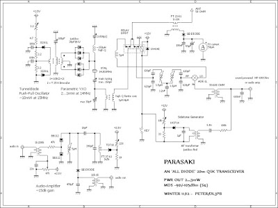
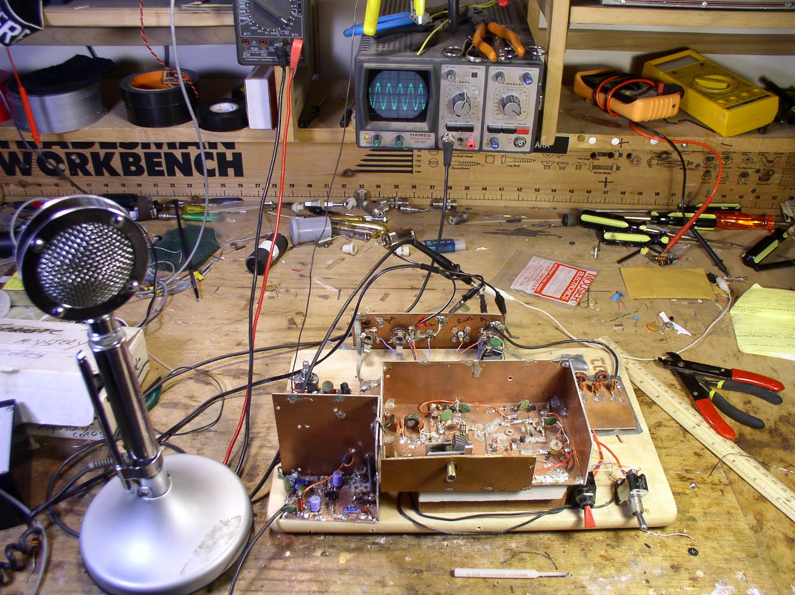
Those interested in the cruel details of my circuit, please find attached a schematic and a photo of the pretty ugly setup. The circuit is designed straight-forward with exception of the parametric VXO, derived from Mike/AA1TJ's famous Paraceiver design. (see http://fhs-consulting.com/aa1tj/paraceiver.html )


The low impedance of the high peak-current tunnel diodes make it very difficult to built a really crystal controlled oscillator rather than an LC-oscillator, synchronized by the crystal more or less, at least on the higher SW-bands. The Parametric VXO provides a crystal-stable, chirp-free signal on expense of an output power of two milliwatts only instead of ten, but with an amazing spectral purity, no need for a low pass filter or such. Of course it sounds pretty cool making a QSO with a 'bunch of diodes' and a parametrically excited crystal, but believe me or not, I'd preferred to bring that full ten milliwatt into the air - on the other hand that approach allowed to tune the rig a bit ( ~ 5kHz/per xtal), which turned out to be much more valuable than a few milliwatts more while being 'rock-bound'.


The receiver in its 'gain-less' version works fine for strong signals - while listening to QRP(p) stations, the moderate gain of the audio amplifier helps a lot. A comfortable frequency shift between receive and transmit is realized by the 5µH inductor at the LO-port of the mixer, with little effect on sensitivity.


Thanks for the bandwidth, OMs, won't bother again you with such mails, unless I make a cross-pond QSO with that rig ( not that likely ) or any skywave QSO with homemade semiconductors ( probably impossible )...


72!


Peter/DL3PB


Our book: "SolderSmoke -- Global Adventures in Wireless Electronics"http://soldersmoke.com/book.htmOur coffee mugs, T-Shirts, bumper stickers: http://www.cafepress.com/SolderSmokeOur Book Store: http://astore.amazon.com/contracross-20

Monday, February 6, 2012

Building a Wright Model D

There is a lot of Knack-like activity in this project. I think you guys will like this show. I'm not sure the Hulu link will work outside the U.S.

http://www.hulu.com/watch/23333/nova-wright-brothers%E2%80%99-flying-machine


There is also a lot of good background info here:

http://www.pbs.org/wgbh/nova/wright/


And as long as we're talking about Knack-related aviation, here's a great article about an avionics engineer who has made a big difference in the world:

http://seattletimes.nwsource.com/html/businesstechnology/2017426408_bateman05.html

Our book: "SolderSmoke -- Global Adventures in Wireless Electronics"http://soldersmoke.com/book.htmOur coffee mugs, T-Shirts, bumper stickers: http://www.cafepress.com/SolderSmokeOur Book Store: http://astore.amazon.com/contracross-20

Sunday, February 5, 2012

SolderSmoke Podcast #141

http://www.soldersmoke.com/soldersmoke141.mp3

February 5, 2012


Recording on repaired computer
RG-174 shield wires: "Murphy's Whiskers"
"The Radio Art"

"Non e radioamatore se non gli fuma il saldatore!"

Does soldering a soldering iron disturb the universe?
HCJB: Home of the Quad, but DX Party line is over
Butane, Loctite, Scotchbrite, Velcro, and Gorilla tape

Getting the 17 meter SSB station going -- trials, tribulations, triumph! MAILBAG


http://Our book: "SolderSmoke -- Global Adventures in Wireless Electronics"http://soldersmoke.com/book.htmOur coffee mugs, T-Shirts, bumper stickers: http://www.cafepress.com/SolderSmokeOur Book Store: http://astore.amazon.com/contracross-20

Saturday, February 4, 2012

QROoooooooo!

Here's a rig that will never be featured in SPRAT or QQ! Welcome to the Gates HC-114: http://www.transmitter.be/gat-hc114.html
(Stephen, G7VFY, sent me this, so blame him if this exposure to QRO causes any psychological trauma.) I note that the rig does have a five element low-pass filter.

Our book: "SolderSmoke -- Global Adventures in Wireless Electronics"http://soldersmoke.com/book.htmOur coffee mugs, T-Shirts, bumper stickers: http://www.cafepress.com/SolderSmokeOur Book Store: http://astore.amazon.com/contracross-20

Friday, February 3, 2012

The Knack, defined

Of course, our British cousins will have some problems with this. (We already have some lexicon problems there -- I can sense many of them wincing every time I say "SodderSmoke"!) But I'm sure they will be understanding here. And indeed, the Knack can sometimes leave you Knackered! (BTW: I currently have an annoying little soldering iron burn on the tip of my right finger.)

Hi Bill,

Maybe I'm not the first to think of these two words, but here goes:

Knacking v/n. as a noun, the act of artfully and cleverly designing, building from scratch, or repairing devices using, usually electronic in nature, specifically amateur radio related...not related to hacking As in: "My knacking was a success and I finally got my Drake 2B working on 30 meters" Somewhat redundant, since knacking IMPLIES extreme cleverness, knacking ALWAYS has a successful result, by definition!

as a verb (as in "Googling") to artfully and cleverly design, build, or repair a device, normally electronic in nature as in "I was knacking my JBOT amp yesterday and successfully added a new low pass filter" Implies high level of cleverness and determination and a modicum of luck


knacker n. one who artfully and cleverly designs, builds or repairs electronics, especially amateur radio related, implies high level of accomplishment and can be used by knackers to describe themselves without embarrassment or outright bragging. Knackers do not need formal training in electronics to fully qualify. Knackers always know who they are and can be identified by burn scars on their fingers from soldering accidents.

Keep your great blog and podcasts going.

73

Steve Silverman
KB3SII

Our book: "SolderSmoke -- Global Adventures in Wireless Electronics"http://soldersmoke.com/book.htmOur coffee mugs, T-Shirts, bumper stickers: http://www.cafepress.com/SolderSmokeOur Book Store: http://astore.amazon.com/contracross-20

Thursday, February 2, 2012

Hard Core! Wisdom and Ideas on Toroids

Gerard ZS5AAC

This morning the BITX20 mailing list has an interesting discussion of toroidal cores. I especially like Gerard's use of the cores from old CFL bulbs. Farhan wraps it up with a great explanation of why we use ferrite cores in broadband transformers:
------------------------------
Over the years I built quite a few BITX's. In the beginning I used the
toroids salvaged from CFL lamps. These worked quite well for the mixer
coils. For the filter coils I used 6mm bakelite slug tuned coils that were
stripped from old PYE radios. Wonder if anybody else experimented
along the same lines. I build my BITX's Manhattan style and they work from the start with few minor tunings. Happy BITX'ing, Gerard, ZS5AAC.
---------------------------------------
Bob
The purists may attack us on this, but what you propose is very
possible. I have been using a wooden-core toroid for several years as part of an antenna tuner.

http://qrp.webhop.net/Pictures/Webcam-1293651325.jpeg


http://qrp.webhop.net/Pictures/Webcam-1295140555.jpeg


I'm also using small plastic and wooden beads as toroid cores for
several other projects. Half inch long sections cut from thick-wall (schedule-40 or schedule-80) PVC pipe also makes good toroidal forms. Beauty of using non-metallic cores is that the core can be split to allow winding wire through the slot without having to thread it through the hole.

http://qrp.webhop.net/Pictures/Webcam-1289957121.jpeg
= 1.4 uh

Bending an inductor back on itself in toroidal form concentrates the
magnetic field in the center, whether the core is metallic or non-metallic. This gives you similar self-shielding properties when using either type core material.

With non-metallic cores you no longer have to worry about core saturation, so running high current finals is not a problem.

Key to doing this is being able to measure inductance of 5 turns, 10 turns,
and 20 turns, so you can calculate and plot the effective AL of your wooden core toroids. Once you know this value you can make up a chart to tell how many turns are required for a specific inductance.

Twisting wires together to make a transmission-line for bifilar or
trifilar windings is interesting because the impedance of that transmission line might affect performance of your transformer. It may require a bit of experimentation with an SWR bridge to tell when you have the best balance between twist pitch, wire diameter, and insulation thickness.
Arv - K7HKL
---------------------------------------------

Robert, Arv,
There are two types of coils used in the bitx - the broadband
transformers and the RF coils in the bandpass filter and oscillators.
You could easily substitute the rf and vfo/bfo coils with just about
any kind of coil - as long as you are hitting the same inductance and
Q. But there is a catch : a few years ago, I finally got down to
measuring the Q of the nylon tap washers that I had originally used.
The q was quite modest at 70. Wes made independent measurements with similar results (his paper is on www.w7zoi.net under technical stuff). In short, for good performance use good old air coils wound on a
cylindrical formers if you don't use toroids.

About the broadband transformers. These need a material that has very
low loss, very high permeability. The reasoning is like this :
1. We need an transformer's inductance such that the reactance is
at least 200 ohms at the lowest frequency. This puts the inductance at
around 30uH at 4MHz.
2. If we achieve 30uH through lots of turns (say 100), each turn will
exhibit capacitance with it's neighbor and the large number of turns
will add up the capacitance so that the coil will provide enough
self-capacitance to resonate at an unintended frequency in HF leading
to pretty bad mixer performance.
3. The only way out would be to achieve the required reactance with
lower number of turns. This means using ferrites.
- farhan VU2ESE


Our book: "SolderSmoke -- Global Adventures in Wireless Electronics"http://soldersmoke.com/book.htmOur coffee mugs, T-Shirts, bumper stickers: http://www.cafepress.com/SolderSmokeOur Book Store: http://astore.amazon.com/contracross-20

Wednesday, February 1, 2012

Success on Seventeen Sideband!

Wow, sometimes scratch-built homebrewing can be a frustrating masochistic activity. Who among us at one point or another hasn't sat back from the bench and wondered why he didn't take up stamp collecting? But then sometimes the radio gods are smiling on you, the smoke stays inside the components, the antenna rope doesn't break, oscillators osc and amplifiers amp and all is right with the universe. I had one of those days yesterday.

The RF feedback measures I described earlier took care of that problem very nicely. Conditions on 17 were not that good yesterday, but as soon as the sun was up I started hearing stations. I called Phil, K5ACR, in Oklahoma and he came right back to me. He said the signal sounded OK, but he thought I might have been driving it a bit too hard. I backed off a bit and he said it sounded very nice.

Our weather was really disturbingly pleasant yesterday (we're not supposed to be out in T-shirts on January 31). I took advantage of it and went out with my fishing pole and sling shot (the neighbors love it) and got a line over just the right branch. This allowed me to turn my low-to-the ground 17 meter inverted Vee into a proper dipole, up about 15 meters or so.

Back to the shack and K5USI said I was booming into Mississippi's Gulf Coast. I turned off my 20 watt linear and he could hear me just fine barefoot. Then I worked K2BQ in Florida. All stations report that the signal sounds very nice.

I remembered that I did a QST article about this transmitter a few years back. I can't find it on the web, but here is an old page that describes it as it was in the last solar cycle:
http://www.gadgeteer.us/17SSB.HTM

Our book: "SolderSmoke -- Global Adventures in Wireless Electronics"http://soldersmoke.com/book.htmOur coffee mugs, T-Shirts, bumper stickers: http://www.cafepress.com/SolderSmokeOur Book Store: http://astore.amazon.com/contracross-20

SolderSmoke -- The Book 20% off. And available for Ipad and Nook

Save 20 percent through February 3. Through the Lulu site you can get the book in the print or e versions.

The book is also available from Kindle, the Ibook store, and for the Barnes and Noble Nook.

Our book: "SolderSmoke -- Global Adventures in Wireless Electronics"http://soldersmoke.com/book.htmOur coffee mugs, T-Shirts, bumper stickers: http://www.cafepress.com/SolderSmokeOur Book Store: http://astore.amazon.com/contracross-20

Tuesday, January 31, 2012

Some Audio Shielding

As I was aligning my "23/24 Re-cycle" 17 meter SSB rig, I noticed the tell-tale sounds of RF getting into my audio. (I guess I should be pleased -- my amplifiers are now producing enough RF to cause some trouble!) So this morning I went in and battened down the hatches in the AF part of the rig. Lead lengths were reduced. Unshielded cables were replaced with RG-174 (with due attention to "Murphy's Whiskers"). A ferrite bead was placed on the wire that carries voltage to the op-amp chip. I wrapped some foil (actually some of that conductive tape used to protect windows in alarm systems) around the plug on the D-104). And finally I cut out two pieces of PC board and made a shield for the whole AF section (see above). I think all this has had the desired effect. The audio sounds clean. I have the day off today, so if there are no Coronal Mass Ejections I hope to make some contacts on 17. Stay tuned!

Our book: "SolderSmoke -- Global Adventures in Wireless Electronics"http://soldersmoke.com/book.htmOur coffee mugs, T-Shirts, bumper stickers: http://www.cafepress.com/SolderSmokeOur Book Store: http://astore.amazon.com/contracross-20

Monday, January 30, 2012

My .02 KW Linear Amplifier

Once again, die-hard QRP guys should probably look away at this point...

My Cycle 23/Cycle 24 refurbishing project continues. The JBOT amplifier in the 17 meter SSB rig is now working nicely, but unfortunately just as I got ready to make some contacts, the Coronal Mass Ejection hit us and conditions on 17 deteriorated badly. Looking for something to do, I noticed that in some pictures of my old Azores station, sitting alongside the SSB transmitter there was a small cabinet with a QRO/QRP switch on the front panel. Ah yes! My Ramsey Kit linear amplifier! This is a MOSFET-based device. Mine was designed for 20, but I changed the low pass filter and put it on 17. Later, in Italy, it went on 20 meters and for some reason I went back to the 20 meter low pass filter.

Yesterday I blew the dust off this thing, pulled out the 20 meter LP filter and replaced it with a filter that will let my 17 meter RF reach the antenna. Today I fired it up. Wow! 20 Watts! Look out 17 meters!

I really like the QRO/QRP switch -- it gives me the opportunity to lean back and say (just like the big guns) "Wait a second Old Man, let me turn on my LINEAR!" I even have a little fan in the box that you can hear when I go to the QRO position. Unfortunately it doesn't make the lights flicker. But we can dream...


Our book: "SolderSmoke -- Global Adventures in Wireless Electronics"http://soldersmoke.com/book.htmOur coffee mugs, T-Shirts, bumper stickers: http://www.cafepress.com/SolderSmokeOur Book Store: http://astore.amazon.com/contracross-20

Sunday, January 29, 2012

Putting 17 Meter SSB Station On the Air

Magnificent, don't you think? The sun is rising over Northern Virginia, and 17 meters is starting to come alive. Yesterday I finished the tweaking and peaking of the JBOT amplifier for the transmitter. It is nice and stable now. (And yes, Steve, it has a low-pass filter!) On top of the transmitter cabinet is the receiver. It is a Barebones Superhet designed by Doug DeMaw and built on a FAR circuit board by Dale Parfitt, W4OP. I changed it to 17 meters and broadened the filter response for use on SSB. Both the transmitter and the receiver use variable crystal oscillators, with two crystals in each (switch-able from the front panels). The frequency coverage of of the transmitter and the receiver match up fairly well (good thing!). Wish me luck! Today I will venture forth amidst the coronal mass ejections and try to make a few SSB contacts on good-ol' 17.

Our book: "SolderSmoke -- Global Adventures in Wireless Electronics"http://soldersmoke.com/book.htmOur coffee mugs, T-Shirts, bumper stickers: http://www.cafepress.com/SolderSmokeOur Book Store: http://astore.amazon.com/contracross-20

Saturday, January 28, 2012

A Good Deal on SolderSmoke -- The Book 30% off!

Thirty percent off from Lulu! That's pretty good! Offer ends on January 31.
See "SolderSmoke -- Global Adventures in Wireless Electronics" at:
http://soldersmoke.com/book.htm

Our coffee mugs, T-Shirts, bumper stickers: http://www.cafepress.com/SolderSmokeOur Book Store: http://astore.amazon.com/contracross-20

Friday, January 27, 2012

Some Amazing German Knack


Michael, DL4MGM, sends us this report from a country in which "the knack" has deep linguistic and cultural roots. Wow, that's my kind of hamfest! Test stations for homebrew gear. And the key-powered transmitter is a great idea. I know there is a lot of energy going into those straight keys -- as a kid, my arm would hurt after an afternoon of unanswered CQs. Thanks Michael!

Hi Bill,
I do not know how big your german listener base is but in any case I want to draw your attention to the "Amateurfunk Tagung München" on 10th and 11th of March 2012. It is a german amateur radio convention which takes place every other year at the University of applied sciences in Munich. There is one speaker track with, mostly german, talks on a wide spectrum of topics related to our hobby. The organisers did a particularly good job in getting Joe Taylor, K1JT, as a speaker to talk on "Recent Advances in Amateur Weak Signal Communication" (10. at 17:00 local time). Needless to say that I'm looking forward to this.
Apart from the talks there will be booths and exhibits from various groups and also some well known commercial sources of RF/microwave components, modules and the like.

Another highlight are the lab places, including personnel, where you can have your home brewed stuff tested up into the high double digit GHz range. I always take home new ideas from just strolling around there and looking at the things people bring for testing...


The last thing I want to mention is the current "operating and construction challenge" because it so right up our alley. It is something like an "Energy harvesting transmitter key". The task is to build a 2m, 80m or 10m transmitter which is completely powered by the energy put into the key movement. In order not to stifle inovations, a lot of liberties are granted such as keying by foot. It will be allowed to pre-charge the energy storage component by keying up to to 10 "v"s with the transmitter turned off. As proof of operation, a 160 character random text message will have to be send to an adjoining room. Ranking criteria (in descending order) will be:
- Peak transmitter power during transmission of the last character. - Construction and handling - Message errors - Keying speed / total transfer time - Tone quality and frequency stability Sounds like it will be a lot of fun... Here the link to the german site: http://www.darc.de/distrikte/c/amateurfunktagung-muenchen/

That's all for now.
Keep going!

Kind regards from southern Germany de
Michael, DL4MGM


Our book: "SolderSmoke -- Global Adventures in Wireless Electronics"http://soldersmoke.com/book.htmOur coffee mugs, T-Shirts, bumper stickers: http://www.cafepress.com/SolderSmokeOur Book Store: http://astore.amazon.com/contracross-20

Wednesday, January 25, 2012

Toroidal Travails II

Steve Smith sent me a good article on broadband transformers. Reading through it, it occurred to me that perhaps using a heavier gauge wire in that PA output transformer might help. So I rebuilt the FT-50-43 transformer and put it in the final. No joy -- output was still down around 1 watt. Then I tried adding two turns to the secondary (on his web page Farhan advises experimenting with the turns ratio in an effort to improve output). Again, no joy. So I went back to the FT-37-43 transformer with 12 turns on the secondary. This yields the best results so far: about 2.5 watts. Still a bit low, but for some reason, the smaller cores seem to do better. Toroidal transformer tweaking to continue... Stay tuned.

Our book: "SolderSmoke -- Global Adventures in Wireless Electronics"http://soldersmoke.com/book.htmOur coffee mugs, T-Shirts, bumper stickers: http://www.cafepress.com/SolderSmokeOur Book Store: http://astore.amazon.com/contracross-20

Tuesday, January 24, 2012

Toroidal Transformers: Does Size Matter?

I continue to tweak and peak the JBOT amplifier in the Azores 17 SSB transmitter. On this version I used some FT-50-43 toroidal cores instead of the smaller FT-37-43 cores recommended by Farhan. This morning I was experimenting with the output transformer. I seem to get noticeably more output with a transformer made with four FT-37-43 cores than I do with one made with four larger FT-50-43 cores.

I noticed something similar on my previous JBOT: performance improved when I switched from some relatively large binocular cores and went to the recommended FT-37-43.

So, what do you guys think? Could there be lower losses using the smaller cores? Any other reason why the smaller transformers seem to be doing better?

Our book: "SolderSmoke -- Global Adventures in Wireless Electronics"http://soldersmoke.com/book.htmOur coffee mugs, T-Shirts, bumper stickers: http://www.cafepress.com/SolderSmokeOur Book Store: http://astore.amazon.com/contracross-20

Sunday, January 22, 2012

Saturday, January 21, 2012

JBOT Installed in Azores 17 Meter SSB Rig

Even though one of their Coronal Mass Ejections is due to hit us soon, the radio gods have been quite kind to me this morning. I installed the JBOT amplifier board in the 17 meter SSB transmitter that I had built out in the Azores during the last solar cycle. The board went in without any trouble. And I was a very surprised when it DIDN'T break into oscillation and instability! Holy Cow! This one was stable from the start! Even when connected to my antenna! Eureka!

The rig still needs some peaking and tweaking. I'm only getting about 2-3 watts out and I should be getting 4-5. I did a quick and dirty "by ear" alignment --- I just listened to my own signal with my trusty Drake 2-B and moved the carrier oscillator freq around a bit until the SSB audio sounded good (you never have to do that with DSB!).


For those of you not familiar with this rig, here is some background:
-- Built on the chassis of an old Heath DX-40
-- Crystal filter at 5.174 MHz. Filter rocks and carrier oscillator rocks from an old Swan 240 I picked up in the Dominican Republic from Pericles Perdomo HI8P (SK).
-- Based on a design published in SPRAT by Frank Lee, G3YCC (SK).
--Heterodyne oscillator is a G3RJV Universal VXO circuit running at around 23.3 MHz.
-- That orange cord to the big meter that you are no doubt wondering about is just a little circuit that monitors total current drawn by the rig. It bounces up and down as I talk. I put it in there mostly because I wanted to make use of a beautiful old Simpson meter that I picked up in 1973 at the Crystal Radio Club (W2DMC) in Valley Cottage, New York.


Going around, clockwise from below the meter: G3RJV VXO, carrier oscillator and two diode balanced modulator board, crystal filter (with NE602 mixer and post-filter bandpass filter to the left), JBOT PA. Audio amp (using op amp) below the chassis. T/R relay in the center (antenna changeover relay below the chassis).

Our book: "SolderSmoke -- Global Adventures in Wireless Electronics"http://soldersmoke.com/book.htmOur coffee mugs, T-Shirts, bumper stickers: http://www.cafepress.com/SolderSmokeOur Book Store: http://astore.amazon.com/contracross-20

Friday, January 20, 2012

The Father of the CK722 (and RadioShack!)

Steve Smith of SolderSmoke's West Coast bureau sent us the link to this article about a very interesting guy who made enormous contributions to the radio art. Three cheers for Norman Krim!
http://tinyurl.com/7qsdq22

Our book: "SolderSmoke -- Global Adventures in Wireless Electronics"http://soldersmoke.com/book.htmOur coffee mugs, T-Shirts, bumper stickers: http://www.cafepress.com/SolderSmokeOur Book Store: http://astore.amazon.com/contracross-20

Thursday, January 19, 2012

DIY at the V&A (Victoria and Albert Museum)

http://blog.makezine.com/2012/01/17/the-power-of-making-at-the-va/

Power of Making from Juriaan Booij on Vimeo.

One of the many perks that I enjoyed during my four years in London was living near that city's amazing museums. I was more of a Science Museum or Natural History Museum guy, but the we also loved the V&A. Each day on my way to work, the 414 bus took me past the V&A's magnificent facade. I always tried to get a seat that would allow me to get a good look.
The Maker Blog reports that the Victoria and Albert recently had an exposition on people who make things in their own private workshops. We are not alone! The video imbeded above is some sights and sounds from the world of DIY. The link below takes you to another video that includes some nice interviews with folks who are making things.

http://blog.makezine.com/2012/01/17/the-power-of-making-at-the-va/


Our book: "SolderSmoke -- Global Adventures in Wireless Electronics"http://soldersmoke.com/book.htmOur coffee mugs, T-Shirts, bumper stickers: http://www.cafepress.com/SolderSmokeOur Book Store: http://astore.amazon.com/contracross-20

Tuesday, January 17, 2012

Another JBOT Amplifier

Over the weekend I built another JBOT 5 watt linear amplifier (design by Farhan). I used a nice piece of copper-clad board that Dave, W8NF, sent me (thanks again Dave).

This time I chickened out regarding the possible conductivity of the anodized heat sinks. I didn't have any trouble with this on my first JBOT, but I worried that if the anodized layer gets flaked away, a heat sink might short one of those collectors to ground. To be on the safe side, I put small squares of Gorilla Tape on under the heat sinks. (PLEASE don't tell me that Gorilla Tape is conductive!)

For T1 and T2 I used FT50-43 toroids instead of the TV baluns used by Farhan. He had recommended FT37-43's as an alternative to the TV baluns, but I went with the slightly larger toroids. For T3 I rolled my own binocular core using four FT37-43 toroids stacked 2X2.

The amplifier has passed the smoke test. Next I have to put in the low pass filter (Steve Smith: Please note that I have left space on the board for the filter.) Then this version will face its real test when it goes into the 17 meter Azores SINGLE sideband rig.

Our book: "SolderSmoke -- Global Adventures in Wireless Electronics"http://soldersmoke.com/book.htmOur coffee mugs, T-Shirts, bumper stickers: http://www.cafepress.com/SolderSmokeOur Book Store: http://astore.amazon.com/contracross-20

Sunday, January 15, 2012

Sunspots: As Good As It's Going to Get

The good news is that conditions are not a lot better than they have been. The bad news is that they won't be getting much better. But take heart guys: the next few years should be pretty good. Now is the time to get those rigs and antennas for the upper HF bands in shape. Construction of a second 17 meter JBOT amplifier begins today (this one for the Azores SSB transmitter).

Our book: "SolderSmoke -- Global Adventures in Wireless Electronics"http://soldersmoke.com/book.htmOur coffee mugs, T-Shirts, bumper stickers: http://www.cafepress.com/SolderSmokeOur Book Store: http://astore.amazon.com/contracross-20

Saturday, January 14, 2012

Warning! QRPers May Find This Disturbing!

Greg, KC2DWF, sent me this link to a really great web site about the AM broadcast station WLW (aka "The Nation's Station"). Brace yourselves guys, for we are now moving out of QRP land: The exciter on this baby is 50 kilowatts! The modulator could produce 400 kilowatts of AUDIO! The article is very well written, obviously done by an aficionado of high power RF. There are some great lines in there. Here is a sample:

This brings up the real fun part of 1934 AM broadcasting -
NO LIMITERS! WLW, like any big-time station at the time, gave the Full Monty: 100 per cent modulation. Now, radio textbooks always have cute little pictures of sine waves at 100%, but people don't talk in sine waves. They don't beat drums, play hillbilly music, or yodel in sine waves. If the studio asked the big rig for some outrageously asymmetrical upward modulation barely crossing zero at all, the DC-sucking beast said FEED ME and obliged - briefly. Voltmeters dipped at the power company, antenna current went haywire, cows felt funny tingles in odd places, and various shotgun-loud bangs and sparks filled the transmitter building.

Have fun, but don't get any QRO ideas...

Here's the link to the article:
http://www.ominous-valve.com/wlw.html

More info and pictures here:
http://www.oldradio.com/archives/stations/cinc/wlwpix.htm

Our book: "SolderSmoke -- Global Adventures in Wireless Electronics"
http://soldersmoke.com/book.htmOur coffee mugs, T-Shirts, bumper stickers: http://www.cafepress.com/SolderSmokeOur Book Store: http://astore.amazon.com/contracross-20

Thursday, January 12, 2012

SolderSmoke Podcast #140

Universal VXO

A new episode of the SolderSmoke podcast is now available:


http://soldersmoke.com/soldersmoke140.mp3

January 9, 2012


-- Santa Claus: Ice Skates, Brownie Box Cameras, and Piper Cubs
-- On the air with 17 Meter Azores DSB rig
-- Seeking balance (with antennas)

-- 23/24 recycling of Azores SSB Rig: Adding Soul to the Old Machine!
-- Attacked by my own soldering iron!

-- RG-174, swarf, and other insidious threats to the homebrewer
-- Inspiration from QRP Quarterly
-- G3RJV validates the D-104
-- T/R admonition from the 1973 Handbook (words to live by)
-- The Woz on electronics and teenage social isolation
-- BANDSWEEP: Straight Key Night at WA6ARA
-- MAILBAG
Our book: "SolderSmoke -- Global Adventures in Wireless Electronics"http://soldersmoke.com/book.htmOur coffee mugs, T-Shirts, bumper stickers: http://www.cafepress.com/SolderSmokeOur Book Store: http://astore.amazon.com/contracross-20

Tuesday, January 10, 2012

Helliwell and the Whistlers

Paul, W2IOG, alerted me to the passing of Robert Helliwell, one of the discoverers of the "whistlers" and an expert on VLF phenomena and the magnetosphere. Paul met him and tells me that he was a real gentleman. His obit is fascinating:

http://news.stanford.edu/news/2011/may/robert-helliwell-obit-052011.html


Our book: "SolderSmoke -- Global Adventures in Wireless Electronics"http://soldersmoke.com/book.htmOur coffee mugs, T-Shirts, bumper stickers: http://www.cafepress.com/SolderSmokeOur Book Store: http://astore.amazon.com/contracross-20

Wednesday, January 4, 2012

Homebrew SSB Portable from Australia


Peter Parker, VK3YE, is one of the true gurus of QRP phone. When I first started building DSB and later SSB rigs, I frequently found inspiration and ideas in Peter's articles and web sites. This morning I came across this amazing video, produced just days ago, showing Peter and his new SSB transceiver in operation from a beautiful Australian beach. The rig is a 40 meter version of Farhan's BITX-20. (I really like the frequency dial.)

Peter describes his rig this way:

It's made from scratch, ugly style, with 99% being from the original design.
It covers 7 to 7.2 MHz, using a 9.05 MHz IF and a 2 MHz VFO.
I used a different microphone amplifier (I got more and clearer output than
the original with my electret mic) and a BD139 driver transistor.
The PA circuitry is also slightly different.
It's been about my easiest and most trouble-free transceiver project to
date. Performance is excellent and a tribute to Ashhar. The furthest distance so
far was a 5/6 report from ZL (about 2000 - 3000km away).

The grand finale of the video is a four-way contact with homebrew rigs in use at all four stations. Excellent. Thanks a lot Peter.

Here is Peter's web site: http://home.alphalink.com.au/~parkerp/

Our book: "SolderSmoke -- Global Adventures in Wireless Electronics"http://soldersmoke.com/book.htmOur coffee mugs, T-Shirts, bumper stickers: http://www.cafepress.com/SolderSmokeOur Book Store: http://astore.amazon.com/contracross-20

Tuesday, January 3, 2012

Las Cruces QRSS Mafia Attacks Pensacola!


OM Dave, WA5DJJ, writes to us about a different kind of SKN -- I guess this would be SLOWWWWWW Key Night!
-----------
Dear Bill,


Hope you and yours have a very Happy New Year.

I agree that Ashhar Farhan is one of the guys that I also admire
mainly because he is trying a valid approach to get amateurs on
the air. His designs are easy to construct, use simple common
parts and work well. I got really tickled when he said that he
kept his parts in two plastic tool boxes. I have so much I have
a hard time keeping mine in a garage with some spillage over to
the storage shed. But alas, I need to downsize.

Keep up the good work with SolderSmoke podcast. You are reaching
a lot of folks and also making a difference.

Our Las Cruces QRSS Mafia had a New Years 2012 on the air celebration
on 30 meter this New Years. We got 14 transmitters on the air and
managed to jam the Pensacola Snapper with so many signals that Bill
couldn't count them all. I attached the sheet I sent W4HBK to
mark the event. There wasn't much room left but others still got
in the holes. We did have a lot of fun plotting the event and getting
the 15 guys installing antennas, building transmitters, and programming
keyers. So, there was a lot of activity here to do the deed.

Anyway, Keep the soldering hot and the projects going. I like your
rebuild of your 17M transmitter. Nice project.

Take care and have fun in 2012.

73 Dave
David R. Hassall WA5DJJ
WEBSITE: http://www.zianet.com/dhassall/


Our book: "SolderSmoke -- Global Adventures in Wireless Electronics"http://soldersmoke.com/book.htmOur coffee mugs, T-Shirts, bumper stickers: http://www.cafepress.com/SolderSmokeOur Book Store: http://astore.amazon.com/contracross-20

Monday, January 2, 2012

2012 Off to a Good Start: Balanced ATU Success!

2012 is off to a good start here at SolderSmoke HQ. I'm planning on putting up an 80-10 dipole fed with open wire (window) line. So I need a balanced ATU. A very simple link coupled design appears in lots of the antenna books and handbooks (1980 ARRL Handbook page 19-8, RSGB's "Practical Wire Antennas" by John Heys, page 86): Just a series LC circuit in the primary and another tuned circuit with a split stator variable cap in the secondary. The junk box was VERY cooperative: I found a big tuning coil (or might it have been two coils?) probably from an old Heathkit DX-40 or DX-60) -- that would work for the secondary coil. Then for the primary I found a smaller coil that would fit perfectly (with one layer of Gorilla tape) inside the secondary. I also found two really pristine 1000 pF air variables (I know, they can't handle much voltage, but, hey, that's one of the benefits of being a QRP guy, right?) I used the HW-7 as a signal generator and this morning did some experiments with different loads. You have to play around a bit with the taps on the secondary, but the ATU seems quite capable of matching loads from about 50 ohms up to at least 10K, and it works from at least 40 meters to 15 meters.

I found it very pleasing to see that SWR meter go down to 1:1. I'll now -- in the finest traditions of ham radio -- wait until the snow starts falling and the wind starts howling before I try to put an antenna in the trees.

Our book: "SolderSmoke -- Global Adventures in Wireless Electronics"http://soldersmoke.com/book.htmOur coffee mugs, T-Shirts, bumper stickers: http://www.cafepress.com/SolderSmokeOur Book Store: http://astore.amazon.com/contracross-20

Sunday, January 1, 2012

Homebrew Hero: Ashhar Farhan, VU2ESE


I wanted to start off 2012 with something inspirational, and here it is: Ashhar Farhan's work bench. I was visiting his site yesterday and found lots of good info, good humor and, indeed, inspiration. Be sure to check out his RF generator project. And the page that gives his thought on tools and test gear. All of it is wonderful -- you'll find lots of evidence of Farhan's long-term case of The Knack, his efforts to put "soul into his new machines" (his kids are mentioned frequently in his descriptions of his projects), and his obvious qualification for membership in the International Brotherhood of Electronic Wizards. I really like Farhan's efforts to design rigs that can be built with parts available all around the world -- a JBOT amp of his design is percolating nicely in my 17 meter DSB rig, and has been crossing the Atlantic almost every day.

As we were throwing a football around yesterday, I told Billy about Farhan. I mentioned that he lives in Hyderabad -- Billy thinks that's one of coolest city names on the planet and plans to work it into the plot of a novel he is working on.

Here is the site: http://www.phonestack.com/farhan/

Three cheers for Farhan! Happy New Year to all!

Our book: "SolderSmoke -- Global Adventures in Wireless Electronics"http://soldersmoke.com/book.htmOur coffee mugs, T-Shirts, bumper stickers: http://www.cafepress.com/SolderSmokeOur Book Store: http://astore.amazon.com/contracross-20
Designer: Douglas Bowman | Dimodifikasi oleh Abdul Munir Original Posting Rounders 3 Column