Podcasting since 2005! Listen to Latest SolderSmoke

Saturday, May 2, 2020

N6ORS's Hot Mustard Phasing Board. And how Phasing Works.


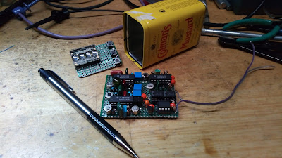
Keith N6ORS is a prolific homebrewer and a frequent contributor to the SolderSmoke blog.  Many of you will remember his MINEX rig.  And who can forget his SDR creation,  called (by him!) "Satan's Digital Radio"?  Well, Keith is at it again, this time working on a phasing rig. 

HI Bill,
Its been a while.  Lately I've been working on a phasing transceiver
that fits in a tiny can.  Its called Hot Mustard. You need hot mustard
when you hamming. I finished the phasing board, its 10 poles , 5 in each
phase branch. here is a pic.  Building the cpu board
next. I'll document this one for a change hihi.
73,
Keith N6ORS

A while back I did a little diagram that -- for me -- explains how phasing cancels one of the sidebands.  It appears below.   I think Keith's board is for the 90 degree audio phase shift.   You can see how, by changing the shift from you can affect the degree of sideband suppression.   I guess by going from -90 to +90 you could completely switch sidebands.  

This diagram shows a direct conversion receiver with the VFO tuned to 7200 kHz.  There is a signal at 7202 kHz and another signal at 7199 kHz.  In a simple direct conversion receiver, BOTH these signals would produce audio tones in the receiver output.  You'd hear both a 2 kHz tone and a 1 kHz tone. Assume you only want to hear the 1 kHz tone resulting from the 7199 kHz signal.  Phasing lets you do this. Here's how: 

-- First split the VFO signal into its "normal" output and an output that lags by 90 degrees (-90) 
-- Consider the output from the top (normal) mixer to be your reference signal. 
-- Because of the lag in the VFO signal going to the bottom mixer,  the output from the bottom mixer will have the 1 kHz signal 90 degrees ahead of the reference signal (+90) while 2 kHz tone will be 90 degrees behind the reference signals (see "scope view") above.  This is a consequence of the mixer math.  
-- Now, in the bottom signal path, shift BOTH audio tones by -90 degrees (in relation to the top reference signal).  I think this is what Keith's board is doing. 
-- With this -90 degree shift, the 1 kHz signal on the bottom path will be IN PHASE with the 1 kHz signal at the top.  But the 2 kHz signal in the bottom path will be 180 degrees OUT OF PHASE with the (top) reference signal path. 
-- The two signal paths are combined before going to the audio amplifiers. The 1 kHz signal is reinforced while the 2 kHz signal is "nulled out."  

The same principle can be used on transmit.  Instead of two receive mixers, you have two balanced modulators.   Both are putting out upper and lower sidebands.  Instead of the VFO you have the carrier oscillator.  By using the same phase shifting techniques you can reinforce one of the transmitter's sidebands while nulling out the other. 


A Toroid Winder from the Wizard of Wasilla -- Paul KL7FLR


Paul KL7FLR has been sharing tribal knowledge with us for several years now.  He recently provided insights on how to tap threads into metal.  In 2017 he told us about his Alaskan road-kill microphone.  And in the midst of the current quarantine he built this really neat toroid winding tool.   Winding coils is often a show-stopper for would-be homebrewers;  Paul's device should help then get past this perceived impediment. Thanks Paul! 

Paul writes: 

A few weeks ago I needed a way of holding a T37-6 toroid to wind an LP filter coil. Being of the fumble fingered crowd I slapped together a quick and dirty holder using a crudely tapered ¼” wooded dowel. As fate would be, I soon needed to wind some other coils of a larger diameter and my wham bam holder wouldn’t do the job. Time to make a holder for more than just one size with the materials I had on hand.


I measured the id of the smallest toroid and the largest toroid I had and plugged them into an online taper calculator. https://www.easycalculation.com/shapes/taper-degree-calculator.php. Calculated taper was 6.65 degrees so I settled on an even 6 degrees with a length of 1 1/2”.  The final of the taper was extended to 3”.  Using my small 6” metal lathe I set the compound to 6 degrees and chucked up a 4” piece of a ¾” wooden dowel. I would have liked to have an ash, maple or other hardwood dowel but I used what I had on hand. Then I turned the 6 degree taper for 3” until the smallest end was 1/8” making the large end almost ¾”. Some sanding with 320 grit sandpaper followed by some ultra-fine 400 grit made it ready for a coat of clear sealer and a quick stain.


Moving over to the milling machine, I set the 6 degree angle with a 6 degree parallel in the vise.  Positioning the mill spindle to the center of the dowel I used a #0 center drill to mill a slot the entire length of the taper to about .015” deep as I didn’t have a 1/32 end mill.  This slot also can be accomplished with a rotary tool or a hobby knife and a steady hand.


I had a couple of 6-32 wood brass insert nuts in the hardware bins. Believe I bought these at Lowes and the Hillman part #880546 is what I used. Drilling a 3/16” diameter hole ½” deep I screwed the insert in until it was flush with the bottom of the dowel. My previous toroid holder had a wooden base but it proved to be too light and easily moved around on my bench.  I dug out a scrap hunk of ¾” steel about 2.5 inches square.  I then drilled a hole through the base using a #27 drill. Now the toroid holder can be mounted on the steel base using a 6-32 machine screw about 1 ¼” long and removed for a different size spindle when necessary. A wood base can also be used with appropriate length wood screw. Be sure to drill a pilot hole large enough in the spindle to prevent from the wood screw from splitting the spindle. A #6 wood screw long enough to pass through the base and into the spindle about ½” would be adequate.

Winding consists of passing the wire up (or down) the slot, lifting the toroid up and rotating slightly and back down on the spindle for the next winding. This has proved to be a very useful fixture when needing to wind some toroid coils.

The picture at the top shows a T-37-6, T50-2 and a T68-2 top to bottom. Will also fit a up to a T-106. Any larger toroids would require a larger spindle to be made.

Enjoyed your YouTube “Quarantined Receiver”  and all the doings from Pete.

Paul
KL7FLR

Idaho Homebrew -- Brian KE7LOY


Brian wrote (on Facebook): 
This (above) is a general Shortwave Superhet receiver I built over the winter. I chose to go modular so I could interchange some of the modules and make easy repairs and changes to the circuits. I used discreet components and only 2 integrated circuits. I built a Colpitt's buffered oscillator which is remarkably stable, a Gilbert Cell Double Balanced Mixer, a high pass filter to filter out local AM broadcast station. The IF chain uses an old classic collins 455 khz mechanical filter amplified by a J310 feeding into an MC1350P IC... It's using 2 germanium diodes as a detector feeding into an LM386 output amp. It's very, very selective and sensitive. I added a 455 khz BFO (lower right in pic) the other day to tune in SSB and CW. This has been a fun experiment.


Friday, May 1, 2020

10 Meter Quarantine QSOs near Boston -- KC1FSZ's Peppermint 10


Hi Guys:

I hope all is well.  Thanks for the more frequent episodes!

I’ve not submitted anything lately but I’m still doing a lot of building.  Over the last few weeks I’ve been working to get myself on 10 meters.  There is some good local activity up here in the Boston suburbs on 10.  The result of this effort is the next in the Peppermint Line of high-performance radio products for the discerning operator: The Peppermint 10.  This rig uses digital VFOs and puts out about 12 watts on a good day.  It works in conjunction with a direct-conversion receiver that has been modified for 10 meters.  The details are described in the write-up (see link):


73s,

Bruce KC1FSZ


Thursday, April 30, 2020

Shortwave Dials -- Exotic Locations -- Hong Kong! Berlin! Springfield? Schenectady?


Click on the picture for a closer look. 

No offense to the birthplace of Homer Simpson, but Springfield?  And Schenectady?  This dial glass is all that remains of a shortwave receiver used by my wife's grandfather in the Dominican Republic. 

Many years ago the Boatanchor enthusiasts had a very informal "dial lights" competition.  Which receiver cast the best glow from its dial lights.  (I think my HQ-100 was the best.)

The dials of many old shortwave receivers have recently started to show up on the Shortwave Listening group on Facebook.  Some have some very exotic foreign locations.   Perhaps we should launch a similar competition:  Which SW receiver dial has the most exotic foreign locations? 


Applied Sciences Workshop Tour

Wednesday, April 29, 2020

Applied Science -- Electrical Impedance Tutorials


Part 1 appears above, Part 2 is below. 

Ben Krasnow has a KNACK for explaining technical things.   I liked his videos on impedance.  At the end of the second video, he said he'd do a third one that would focus on impedance in coaxial cables.  But I couldn't find it on his channel.  I hope it was made -- this is very interesting and useful.   

Ben's YouTube channel is here: https://www.youtube.com/user/bkraz333

Monday, April 27, 2020

Listen to Homebrew-to-Homebrew Quarantine Contact with Glenn KU4NO on his 37 year-old Homebrew SSB Transceiver


This was really amazing.  I had been feeling guilty about not getting on the air much during quarantine.  I mean, we have these airwaves and we have the gear, right? Shouldn't we be more social, more friendly and get on the air more?  I tried yesterday with marginal results (conditions were poor).  I called CQ on 40 SSB this morning -- nil, except for one grumpy guy who said I was splattering on his morning coffee clatch. Then I heard KU4NO calling CQ.  I did not recognize the call.  But when I told him I was on a homebrew transceiver, he matter-of-factly sad that he too was on a homebrew rig.  When he started to describe it  (see below), it all came back me.  His is one of the most soulful of homebrew SSB rigs.  And I realized that it may also be THE OLDEST HOMEBREW SSB RIG STILL IN USE IN THE WORLD.  (If anyone knows of a homebrew SSB transceiver older than 37 years and still on the air, please let me know.)  This was exactly the kind of contact that I needed.  TRGHS. 

Glenn put out a lot of homebrew wisdom.  He said a lot of inspiring things.  (He did also at one point talked about wanting to shoot his plasma TV, but that's understandable.)  So I recorded most of our contact.  (I have his permission to put it on the web).   

You can listen to our contact via the YouTube video above.  

For my report on an earlier contact with Glenn click here: 
https://soldersmoke.blogspot.com/2018/07/a-rig-with-maximum-soul-5-band.html

So, it is worth it to get on the air.  They are rare, but people like Glenn are out there, running very interesting rigs. And when you find them, you feel like you've hit the jackpot. 

Thanks Glenn! 


Saturday, April 25, 2020

SolderSmoke Podcast #221 is available -- Quarantine Rigs, Phasing, SWL, Parts Suppliers, Mailbag

Q-31.  "Roll-bar" on cap.  Note RGS316 coax between stages. Country markings on tuning dial
SolderSmoke Podcast #221 is available: 

25 April 2020

http://soldersmoke.com/soldersmoke221.mp3


Obviously no travelogue.   QUARANTINE.  SITS.

Good news:   Lawyers at Dewey Cheatham and Howe report that SolderSmoke will NOT be taken off the net for brazen promotion of the S-38E receiver.
Also some good news on the FT8 vs. FT-FAKE issue.  That report itself was fake.  

PETE’S PROJECTS:

Phasing SSB
And what’s this about a tube CW rig?
Dean KK4DAS builds Pete’s Simple SSB rig. Quarantine Rig: The Furlough 40.  See: https://kk4das.blogspot.com/

SHAMELESS COMMERCE DIVISION:  NEW AMAZON LINK IN THE UPPER RIGHT SIDE OF SOLDERSMOKE BLOG. .

BILL’S BENCH:

QUARANTINE PROJECT:    Q-31 AM SW Receiver.  April 4 through April 19.   15 days of fun.   Learned a lot. 
Need to pay attention to total gain.  Need to measure.   Not always easy.  My resistor-based technique.
AM detection can be more difficult than SSB/CW detection.  Germanium diodes make a big difference.
But…I don’t have to build a BFO, because these signals bring their own beat frequency.
455 CAN BE PROBLEMATIC AS AN IF – image response, making impedance matching transformers tough at those low frequencies.   But WIDE filters available.  
LM386 AF chip make a LOT of audio.  Hard to reproduce these great results. 
Great stuff you can listen to on 31 meters (9.4 –10 MHz):
n  DX WaveScan
n  WRMI Rock and roll
n  VORW music show
n  Radio Nacional De Espana (Madrid)
n  China Radio International  soap operas and Confucius philosophy lessons.
n  China Radio International Chinese Lessons.
n  Radio Greece
n  Radio Republica (France)
n  Radio Havana Cuba
n  Radio Saudi Arabia
n  WBCQ – They advised listeners to fix up an S-38 during quarantine! !!!!!!!
n  WWV

SHOPPING BAG -- THINGS TO GET:

-- Great source for hardware (screws, nuts, bolts and more):  McMaster-Carr   https://www.mcmaster.com/ 

-- Thermax RGS316 coax.   Great stuff.   Thanks Jim  In some ways better than Belden 1671A https://soldersmoke.blogspot.com/2012/03/murphys-whiskers-shaved-with-belden.html

-- Copper Clad board:  Pete’s boards use CEM 1. CEM 1 is low-cost, flame-retardant, cellulose-paper-based laminate with only one layer of woven glass fabric.


NEED/WANT: 

-- Thermaleze magnet wire.  First encountered in QRP GUYS EFHW tuner kit.  Very FB
Resistor kits
NP0 cap kit
Replacement Iron for XTRonic 4000 Iron.
RIGOL PROBES Why do we burn through so many of these?


MAILBAG:

-- Eric 4Z1UG Episode 300 Special
-- Farhan working on ventilators. Special thanks to Dr. Gordon Gibby KX4Z. 
-- Jonathan-San working out of new shed in Seattle
-- Grayson reminds us of the Fran Lab: https://www.youtube.com/channel/UCMLgHbpJ8qYqj3CkdbvC0Ww
-- WRMI likes SolderSmoke
-- Peter VK2EMU continues to build his amplifier.  But it is NOT for 50 MHz.  It does have 6 different meters on the front panel.  But it is not a 6 meter rig!
-- Rich K7SZ – “now look what you’ve done”   Fixing up an S-38
-- Rich WD3C  Provided some great SWL links:
https://www.short-wave.info/ if you move the green dot to your location it will predict what the signal strength would be at your location and will also allow you to search by station, language, frequency, etc. 
Thomas Whitherspoon, https://swling.com/blog/  Another, https://shortwaveschedule.com/ and of coarse https://www.hfunderground.com/board/index.php all the pirate broadcasters show up here. 
-- Paul KL7FLR amazing S-38E diagnosis from afar. Paul's toroid tool (more to follow on this). 

Pete's Quarantine 6V6 Rig


Thursday, April 23, 2020

WA7SKT's Al Fresco DSB Rigs


Loren WA7SKT wrote: 

Got the balanced modulator and first RF power amp board mounted today for my 20 meter DSB transmitter (above). Still have to build carrier oscillator and final RF power amp boards yet. Coax with BNC connector is carrier osc input to bal mod. As is puts out 8.5mw into 50 ohm load.

Audio in through 2N3904 emitter follower to SBL-1 balanced modulator. Rf out to a 2N4401 Class A RF amp. Will have a final RF power amp stage and to the lowpass filter. Targetting 250mw output max for WSPR. Will add the 2N3904 Colpitts oscillator with tuned collector for carrier oscillator. Power supply will be 9 volts and 12 volts.

This is part of my fun in eventually building a 20 meter SSB transceiver. I am not interested in anything multi-band. This is my second DSB transmitter. First is larger and uses Si5351 for carrier oscillator.

I also plan on building a WSPR transmitter using an Arduino and Si5351 synthesizer so I dont need my PC.  There is a frequency shift program for Arduino to control Si5351. I use Si5351 now for VFO’s. My first WSPR transmitter uses one just for carrier oscillator.

Loren's First DSB Rig

I like Loren's self description on Twitter: 


Wednesday, April 22, 2020

Jonathan-san (Our Man in Japan) Now Melting Solder in Seattle


Got a nice note from Jonathan W0XO.  He and the family  have relocated to the Seattle area.  Here we see Jonathan at work in his new shed/shack.  It looks great. 

Long-time SolderSmoke fans will remember Jonathan from his previous life in Asia. See: 

Tuesday, April 21, 2020

Please Listen: Something Wrong with Spanish National Radio Signal?


I've been getting back into shortwave listening. One of my favorite stations is Radio Nacional de Espana (Spanish National Radio) from Madrid.  It is very strong here on 9690 kHz starting around 1645 Eastern Time, 2145 UTC.  

If you can, please listen to this station and let me know if you hear any technical problems with the signal.  Please let me know what you hear.  Does the signal sound OK.  Any problems? 


Monday, April 20, 2020

Dean KK4DAS Builds SSB rig, Makes First Contact.


You can almost see the excitement in the notes (al fresco!)  of Dean KK4DAS.   He made his first QSO with a homebrew transceiver this week.   Not long ago Dean was taking his first tentative homebrew steps with a Michigan Mighty Mite.  Wow, he has made great progress.   


Congratulations Dean! 


DX WaveScan


I heard this program this morning on my Q-31 receiver.  It was on WRMI 9955 kHz at around 1330 UTC.   

It reminded me a lot of the DX listening program of HCJB.   Good stuff. 

You can listen to the programs on-line at:  https://awr.org/program/engmi_wav/

Sunday, April 19, 2020

Q-31 Quarantine Receiver -- All Boxed Up, Almost Done


Almost done.  A few odds and ends remain, but now I have all the circuitry in their boxes. 

As I was taking my walk the other day I was thinking of how I didn't have to build a BFO for this superhet. That's because the signals coming in on this rig bring with them their own BFO signal (the carrier).  

Saturday, April 18, 2020

Q-31 Quarantine Receiver -- +30 db and a Germanium Diode Help a Lot (video)


Today I added two additional stages of IF amplification.  This added 30 db to the receiver's total gain.  That helped a lot.  I also discovered that Germanium (1N34A) diodes work a LOT better as AM detectors than do silicon diodes.   This receiver is starting to sound decent.  Currently listening to the VORW program on WRMI Miami.  

Friday, April 17, 2020

Walter's VFO

Main VFO board under plastic -- buffer board off to the right
There is a lot of tribal knowledge in this short article by Walter KA4KXX.  (The most recent issue of SPRAT has a picture of a SPRAT cover from more than 30 years ago, announcing an article by Walter.  OM has been at this for quite a while.)  Walter's advice is similar to that of Doug DeMaw, especially on the air-core coil.   FB Walter,  thanks for sharing.  

Regarding the last line in Walter's article, please direct any complaints about drifting analog VFOs to Peter Juliano.  He will be delighted to receive these complaints, and will promptly provide all correspondents with very succinct advice on how to overcome the instability.  

My Way to a Low-Drift Analog VFO, by Walter KA4KXX

I recently built a digital VFO (from a QRP Labs Kit) to see what everybody is talking about, and it has been quite handy for my first two-band homebrew transceiver, but by the time one adds the low pass filter, a low-level RF amplifier to boost the weak output, a 5 VDC regulator, and a hefty +12VDC power line filter to the beast to keep the digital noise out of the rest of the radio, for a single band project I still prefer a low-drift analog VFO.  

My approach to minimizing drift is very simple and works well for a VFO range of 3 – 7.3 MHz, which is all that is needed for the 20 to 80 Meter bands, either direct conversion (adding a doubler for 20M) or single conversion with approximately a 10 MHz IF.  

First, see my schematic (adapted from Small Wonder Labs 40+ transceiver, original BITX40 Analog VFO, and other sources) and wind an air core inductor with stout magnet wire such as 24 or 22 AWG.  Use a thick, rigid plastic form of a diameter so that you need about 12 turns, and single coat with water-based sanding sealer, Q-dope, or similar.  Use hot glue to mount the coil firmly to the single-sided circuit board, and build a cover of some type, especially if the radio is to ever be used outdoors.
   
Second, all the VFO capacitors (except power supply bypass) should initially be the modern C0G type, which can be obtained from Mouser (such as TDK FG28C0G1H681JNT06 or the like), which I trust more than those labeled NP0.

Then, power up the VFO and tweak the coil, tuning arrangement, and range capacitor to get the frequency range you desire.

Next, monitor the drift from a cold start to see how fast it is moving as it warms up, and whether it stabilizes nicely (my goal for SSB Phone use is less than 20 Hz drift during any 10 minute period) after 10 – 15 minutes maximum.  If it does not stabilize to your satisfaction, then start substituting polystyrene caps for the C0G units one at a time until you are happy with the performance.

[Also remember that a stable BFO is important as well, and if you use the BITX 40 crystal oscillator design, I recommend installing a dedicated 78L09 power line regulator.]

If you build this VFO at the higher (7 MHz) frequency end, just change the inductor value to about 0.5 uH, with everything else about the same, but expect to do more tweaking to get stability, and the warm-up time may be closer to 15 minutes.  After years of experimenting, this is what has worked for me.  If it works for you, please send me an email (see my QRZ page) of thanks.  If not, file a complaint with Soldersmoke. 


Thursday, April 16, 2020

Q-31 Quarantine Receiver -- First Signals (Video)


It still needs a lot of work, but today it pulled in its first shortwave signals.  See video.
Designer: Douglas Bowman | Dimodifikasi oleh Abdul Munir Original Posting Rounders 3 Column