CLICK ON IMAGE TO ENLARGE
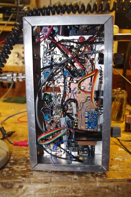
This is a rig that came together through a process of Spontaneous Construction. It started out with an innocent effort to get an Organic Light Emitting Diode display to work with an Si5351/Arduino combination. Then I figured I'd make a superhet receiver with it. Then Pete said I should make it a transceiver.
Most of my earlier transceivers so closely followed the schematics of Farhan or others that it didn't really make sense for me to prepare a new schematic. This one was different. So I decided to prepare a proper schematic. I tried a few of the free-ware CAD or drawing programs, but each of them had a learning curve at the entrance. So I turned to LTSPICE. I have already climbed that learning curve.
The results appear above. Click on the image to make it bigger. I'm sure there are errors in there. And I think some of my parts choices might be less than optimal. But it works well.
The filter was deigned with the help of AADE software.
The idea of using two NE602s with a filter between them came (I think) from the Epiphyte.
The band pass filters were designed with ELSIE software.
The RF power chain is mostly from Farhan's BITX40 module, with the pre-driver and driver modified for a bit more gain. Farhan's amp is the most stable power amplifier I have ever used. It hasn't given me any trouble, even at 20 Watts. Strongly recommended.
The microphone amp is derived from the 741 op amp circuit used in the (in)famous Wee-Willy DSB rig.
The receiver AF amp also comes from Farhan's BITX40Module.
Please let me know if you spot errors or have suggestions for circuit improvement.
A link to the .asc LTSpice file appears below. Perhaps some brave soul more skilled in LTSpice than I am might want to turn this drawing into an actual simulation. Some of the parts (like the NE602s) have actual simulated components behind the drawings. Others (like the relays and the LM741 and LM386) are just drawings. But go ahead and flesh this thing out. Who knows, it might come to life in the PC and start making QSOs on 40!
Here is the .asc file: http://soldersmoke.com/NE602 Rig.asc


Would you be willing to share the LT Spice .asc file with us?
ReplyDeleteMost of it is just a drawing, without the LTSpice models. The '602s have the models, but not the LM386 nor the 741. I have not modeled the crystals. But portions of it (like the RF chain) do lend themselves to LT Spice modeling. I will try to share that portion of it soon. 73 Bill
ReplyDeleteI would not try to model the entire circuit in LT Spice. My reason for the request is that it would be easier to see. My vision is not what it once was.
ReplyDeleteDavid: I understand. I will try to post a link to the .asc file later today or tomorrow. I hope this helps. And perhaps someone more skilled than I with LTSPICE might take the file and complete the models for the sub-circuits, or perhaps the whole thing. 73 Bill
ReplyDeleteLooks almost like the radio I'm building, only my IF is 4.9152Mhz
ReplyDelete
ReplyDeleteReally cool idea and rig.
Pete
actualy this is transceiver KAYMAN1 , with modified transmitter section. in last week I also make this rig. will be copy your transmitter (i have thise components) https://www.facebook.com/photo.php?fbid=1615251628486278&set=a.1146885305322915.1073741826.100000043691492&type=3
ReplyDeleteand this is first test vidio from last night :) https://www.facebook.com/dimitarhorus/videos/1615245978486843/
ReplyDelete