Podcasting since 2005! Listen to Latest SolderSmoke

Showing posts with label Filters. Show all posts

Monday, January 10, 2022

Exorcism Not Quite Complete -- Thinking of Other Options

As often happens, I may have jumped the gun in declaring the exorcism of my 17 meter transmitter to be a success. As readers of this blog will recall, my problem was that when trying to "net" my separate 17 MHz receiver and transmitter, at around 18.116 MHz I could hear more than one tone as I tried to get to zero beat.  The 8th harmonic of my 5.176 MHz carrier oscillator was mixing with the 23 MHz VXO signal and producing a spur.  I could probably knock the level of this spur down below FCC limits, but -- and here is the problem -- I probably could never knock it down to the point that it would not be audible in the sensitive receiver that sits right next to the transmitter.  So this is really a netting problem, not really a spur problem. 

I don't want to try another filter frequency -- I have VXO crystals that really work only with a filter at 5.176 MHz.

So here is my current idea:  Build a receiver board and turn this thing into a transceiver.  Switch with relays the input and output of the 5.176 MHz filter, and use relays to switch to the receiver board the VXO and carrier oscillator signals. 

Making this thing a transceiver would eliminate the need for netting.  This should solve my problem. 

What do you folks think? 

73  Bill 

Thursday, December 30, 2021

McCoy SSB Crystal Filters (1963) -- But Apparently NOT the Real (Lew) McCoy

 
Last month we were talking about this company.  Someone thought it was run by Lew McCoy of ARRL Homebrew fame, but it now appears that our Lew McCoy was not involved in the company. 

Note how they provide TWO carrier oscillator/BFO crystals for each 9 MHz filter, one for USB, the other for LSB. 

They were pricey too:  In 2021 dollars, that Golden Guardian would cost $390. 

Thanks to the K9YA Telegraph for posting the ad. 

Sunday, December 12, 2021

Hack-a-Day: Has DIY become Click-and-Buy?

https://hackaday.com/2021/12/11/has-diy-become-click-and-buy/


Hack-A-Day today asks about the boundaries between DIY construction and the use of purchased, completed electronic components.   This is closely related to our long-standing discussion of what really constitutes "homebrew." 

Is it really homebrew if you buy a bunch of  already-stuffed PC boards and connect them together?  

Is it really a homebrew receiver if 90% of the components are inside one chip? 

Is it really homebrew if most of the signal processing is done in your computer (that you definitely did not build)? 

The comments below the article are interesting.  There we see some of the same arguments used by ham radio operators who are more inclined toward click-and-buy. They argue that since none of us are making our own resistors and transistors, we are ALL therefore click-and-buy people, so we should just get over it and pull out the credit cards. Some commenters carry this to extremes and ask if the real homebrewers are out there mining the copper for their wires.  

The debate seems to spill over into the software area:  One person asks if it is really DIY if you are using software libraries that contain code written by someone else.  Or to be truly DIY should you write all of your own code in assembly language?    

There is one very insightful comment about hams who are inclined to disparage the homebrewing that they did in their youth.  We often hear this:  "Oh, I used to build my own gear, but now-a-days I just buy commercial transceivers -- they are so much better."  As if homebrewing was a folly of youth, something that they grew out of (and up from) as they became able to afford the latest ham radio appliances.  As if homebreweing were a regrettable thing that was done only out of necessity.   This is, I think, sad.  

I think I'm a lot closer to the traditional concept of DIY than I am to click-and-buy.  I still prefer LC oscillators to Si5351/Arduino combos.  I prefer traditional filter rigs to SDR rigs.  And I prefer to make my own crystal filters.  I don't like to use ICs unless I really understand what is going on inside them (so I can be comfortable with an NE602 or an LM386, but I'm not comfortable with a CPU chip that may have millions of transistors in it).  But I am not homebrewing my own transistors nor am I mining copper. 

What do you folks think about this? 

Tuesday, December 7, 2021

Junk Box Sideband from the Azores (2004 QST Article)


About 20 years after I first built it, I find myself working on and using this SSB transmitter.    I recently added some impedance matching to the Swan 240 crystal filter;  several years ago I replaced the PA with a "JBOT" amplifier designed by Farhan VU2ESE.  I now have it on the air, using it with a highly modified Doug DeMaw, Barebones "Barbados" superhet  receiver. I had my first (recent!) QSO with this station yesterday, with Les 6Y6Y on the beach in Negril, Jamaica. 

More on this project in due course. Lots of soul in this machine. 

I'd forgotten about this article -- thanks to Pete Eaton for reminding me. Click on the images for a better look at the article. For an even clearer view, download the images and then open them on your computer. 


Sunday, November 21, 2021

KG7TR's Magnificent 75S-2B Receiver -- Tubes, an Si5351, an Arduino, a Bit of Collins, and a Bit of a Drake 2-B


Oh man, I share this with much trepidation because the last time I posted something about the work of Mike KG7TR,  Pete N6QW said he felt like putting all of his own work in the dumpster, so much better was the artistry of KG7TR.  This receiver is so cool and so well-done that we now  might have to post a guard outside the N6QW shack -- heck Mike even has an Arduino Uno and an Si5351 in there!  Don't do it Pete!

I was led to this magnificent receiver by the very humble 6U8 tube.  Scott  WA9WFA and I have been learning (mostly from Grayson KJ7UM) that the much used and sometimes loved 6U8s (three of them in our "Mates for the Mighty Midget")  might be a bit long in the tooth, old even by Thermatron standards.  I was worried when I remembered that my Drake 2-B has a 6U8 in it -- V2, the first mixer.   So I Googled for more info and was led to this amazing receiver, a 2018 creation by KG7TR.  How did we NOT see this for almost four years?

Here is more info and pictures: 

http://www.kg7tr.com/75s-2b-receiver.html

Here is Mike's write-up of the project: 

http://nebula.wsimg.com/c2281e9bdf3b54da42ca4b0b541b4ec9?AccessKeyId=D18ED10DA019A4588B7B&disposition=0&alloworigin=1

Mike KG7TR's web site:

http://www.kg7tr.com/ 

As for the 6U8s, well Grayson says the tube has been getting something of a bum rap.  And  KG7TR has two of them in this receiver, so I will obviously have to give the 6U8 another chance.  

--------------------

I didn't know that Lew McCoy had his own crystal and crystal filter company: 

http://www.kg7tr.com/the-real-mccoy.html

Saturday, November 20, 2021

The Double Crystal Lattice Filter in the Swan 240 -- Smoothing it out with a NanoVNA


In SolderSmoke Podcast #234, I said that I was scrutinizing the filter from the Swan 240 that I had picked up around 1994 in the Dominican Republic.  I cannibalized it out in the Azores in the early 2000s and used the parts to build -- among other things -- my first SSB transmitter.  I never really focused much attention on the filter that I pulled out of that old rig -- I was just happy that it seemed to work. But I am now older and wiser, and I have some test gear that lets me look at the passband of that filter. 


First, take a look at what it is supposed to look like.  This is from the manual.  Yikes!  That passband looks far from flat.  I can almost hear homebrewers around the world shrieking in horror and disgust.  


Above is a description of the filter, and the schematic, again from the manual. 


Here is what my extracted and somewhat re-built filter looked like in my NanoVNA (more shrieking!).  The dip in the passband is a lot worse here -- it looks like 10 db vs. 3 db in the manual.  This is probably because I'm not even attempting any impedance matching on the filter -- it is just seeing the 50 ohms in and out of the NanoVNA. 


Here is my 2002 attempt to rebuild the filter and put it in my SSB transmitter, along with my more recent attempt to flatten the passband.  I no longer had the adjustable coil L8, so I made my own coil based on guidance from Ben Vester W3TLN's January 1959 QST article on "Surplus-Crystal High-Frequency Filters." (Ben had an early influence on Pete Juliano's tube-rig  designs.)  In the picture above I have 1k pots between the filter and the input and the output of the NanoVNA, as described by Nick M0NTV


Adjusting the 1 k pots, I could smooth out the passband quite a bit.  Measuring the pots and adding the 50 ohms of the NanoVNA, it looks to me like this filter is smoother with about 280 ohms at the input and output.  I may build two matching networks or some transformers. Some TIAs may also be needed. 

Wednesday, November 17, 2021

SolderSmoke Podcast #234: PSSST, KWM-1, VHF Woes, Mighty Midget, TinySA, 17-12 Dual-Bander Advice Needed. MAILBAG


SolderSmoke Podcast #234 is available: 


Roots of SolderSmoke: The "Click and Clack" of ham radio? 
Influences: Jean Shepherd, CarTalk, Shortwave stations.
Steve "Snort Rosin" Smith WB6TNL?  No. Steve "Aching Sinus" Smith WA6SOC  

Pete's Bench:
PSSST Super Simple SSB -- 7 Transistors. Switching IF Module: 
PSST Details:  https://www.n6qw.com/PSSST_20.html
DC RX.
KWM-1 Resurrection "Shame Shelf".
How to make things work:
(Why the T/R diodes in the BITX 20 amplifiers?)
National Receiver.

Bill's Bench
Farhan's Talk to RSGB got me thinking of VHF 2 meter AM.
2 meter Benton Harbor lunchbox madness. SuperRegens Super Strange.
I broke my Maplin AF Sig Gen in the process. Fixed it.
Playing with MMMRX again. Put in 6 kHz ceramic filter. Sounds great SSB and AM.
Swept IF with noise, TinySA, and NanoVNA. Need better noise gen.
Mod to listen with TinySA (on blog).
Thinking of 17 meter /12 meter Dual-Bander IF around 21.4, VFO around 3.41 Mhz. Thoughts?
Sweeping double half lattice filter from Swan 240.  UGLY.  

MAILBAG:
--- ROOTS OF MAILBAG: Radio Moscow, Havana Cuba, HCJB, others.
-- Thomas K4SWL of the SWL Post: Could have been worse! Stairbag?
-- MY NOVICE LOG -- Heard back from ex-WN2RTH ex-WN2FLK ex-WB2RKK.
-- Drew N7DA worked Wes W7ZOI in Sweepstakes. FB.
-- Peter VK2EMU The movie Frequency and the Magic of Heathkits. Good, but not that good!
-- Thomas KK6AHT! Our old friend. Minima! Now has a young son! FB
-- Chuck WA7ZZE Saw QST profile. Sympathizes with Two-er trouble.
-- Tim M0CZP. Spell corrector. Vatican Diodes. Infallible!
-- Ramakrishnan VU3RDD Working on a NORCAL and a noise cancellation arrangement.
-- Skip NC9O said I was 40 Hz off on 17. But he had a reason to KNOW!
-- Steve K9NVD Glad he's a listener.  
-- Bob KY3R Novice Nostalgia. Should he use 75 watt bulb for dummy load? Yes! 
-- Todd K7TFC Video about why solder smoke goes into the face.
-- Anthony VU3JVX  Homebrew Antuino. I ask for help in moving freq to 450 kHz.
-- Jack NG2E Building Pete's DC RX.
-- Scott WA9WFA HBR-13 and MMMRX.
-- Stephen 2E0FXZ also got a FT-101 VFO.
-- Bob K7ZB on the air with 56 mW and a big antenna.
-- Dean AC9JQ Retired.
-- Allan WA9IRS Right to Repair update.
-- Farhan Invited us to Lamakaan ARC, Dec 11 or 12. Will be on QO100 Satellite Live! 
-- Many suggestions about my Apollo 11 Time Capsule. Still looking for ideas.

Happy Thanksgiving to all who celebrate this holiday!

Monday, November 15, 2021

SSB History: Selling SSB in 1954


K9YA Telegraph ran (on Facebook) this ad from 1954.  It provides an interesting view of where phone operations were in that year.  Note that Dale was so intent on selling SSB gear that they were willing to make on-the-air schedules to demonstrate SSB superiority.  

Dale claims that with SSB you could have TWO roundtable QSOs on the same frequency, with one group on USB and the other on LSB.  I think this assumes really great opposite sideband rejection in the transmitters, and excellent selectivity in the receivers. That might have been a bit of a stretch.  But the assumption here was that hams could use USB or LSB -- no rigid adherence to the USB/LSB convention.  And the ad seems to focus on the 75 meter band which was seen as the most important phone band at that time. 

Dale was selling Collins mechanical filters for 55 dollars.  That is the 1954 equivalent of $566 dollars today.  No wonder the phasing method was so popular.  Note that they were selling Central Electronics phasing rigs right next to the ad for the Collins filters. 

I like the graph showing opposite sideband rejection with the Sideband Slicer.  Note that the selected sideband was referred to as the "exalted" sideband.  All Hail the Single Sideband!  

Friday, November 12, 2021

Mate for the Mighty Midget with 6 kHz Ceramic Filter


I built this receiver back in 1998, but I continue to have fun tinkering with it. I wrote an article about it for "Electric Radio" magazine (Number 115).   One of the major shortcomings was the crystal filter that Lew McCoy prescribed.  It was very difficult to get 455 kHz crystals to work well as filters.  At various times I've had all kinds of replacements in there in place of Lew's filter:  a 455 kHz IF can, a Toyo CM-5 hybrid ceramic filter, a fancy Millen high Q IF transformer. None of them really worked well. 

Recently I put a little +/- 3 kHz ceramic filter in there.  This is a 6 kHz wide filter at around 455 kHz.  I think it works really well.  Above you can see the receiver in action.  I use it with a little powered computer AF amplified speaker -- I just don't like headphones.  


The latest  filter mod with the 6 kHz ceramic filter  is shown above. 


Above you can see what the whole 455 kHz filter and transformer passband looks like. The input was through a 2k resistor placed between the .001 uF cap and the filter. The output was also through a 2k resistor placed at the top of the secondary of T1. (So don't pay any attention to the insertion loss.) 

The NanoVNA is displaying 2 kHz per division.   I put the BFO at 451 kHz.  This results is excellent opposite sideband rejection.  The filter is really too wide for SSB, but it is about perfect for AM, which I listen to quite often on both 75 and 40.  SSB and AM both sound quite good.  Check out the video above. 

It is kind of amazing what can be done with just three 6U8 tubes. 

There are many previous SolderSmoke blog posts about the Mate for the Mighty Midget Receiver here:
https://soldersmoke.blogspot.com/search?q=Mighty+Midget   Be sure to keep selecting "earlier posts" so see more. 

Saturday, November 6, 2021

M0NTV's "Crystal Filters for the Fearful" (video)


I really liked Nick M0NTV's approach to making a crystal filter (see video above).  He really simplifies a process that desperately needs simplification. I remember when I was building my first superhet receiver,  I came across Doug DeMaw's schematic for a crystal tester that would allow me to properly build the filter.  But the piece of test gear was far more complicated than the receiver I was building.  I never built Doug's device. 

Nick's technique is simpler even than the G3UUR method that many of us have been using for years.  Nick dispenses -- wisely I think -- with the need to calculate motional parameters, Q,  and equivalent series resistance.  This also eliminates the need to fidget around with the design software such as Dishal or AADE.  

Nick uses the Cohn topology (good choice) and uses kind of an "informed cut-and-try" technique to come up with the capacitor values.  

Filter impedance is determined with series trimmer resistors and the NanoVNA to watch the resulting passband.  Nick says this is a Charlie Morris ZL2CTM suggestion.  It obviously works very well -- the ripple that would result from impedance mismatch is eliminated.  

Nick's determination of the best turns ratio for the impedance matching transformers is brilliant.

Nick apologizes for what he says is a long video.  But it is only 30 minutes or so long, and if you are going to build your own superhet or SSB filter rig, it is well worth watching.   

Three cheers for Nick and for Charlie!  Thanks guys!   

Friday, November 5, 2021

The Importance of Keeping the Noise FLAT


A few days ago I put up a blog post about using a noise generator (in my case my cheap FeelTech sig generator) and my TinySA spectrum analyzer to look at the passband of a crystal filter.  I was using the 9 MHz filter used by Dean KK4DAS and the Vienna Wireless Makers Group.  The idea is simple: insert broadband noise into the input. The filter should pass more of the noise that falls within its passband.  The TinySA should let you see this.  At first, I was pleased that I could clearly see the passband.   I thought I had succeeded.  See above. 

But I was bothered by something.  Look at that bump in the passband.  It should be close to flat across the top.  

I decided to take a look at the same filter with my NanoVNA.  Here I was not using a noise generator.  The NanoVNA sweeps the filter using and looks at output in the Log-Mag mode.  Here is what it looked like (below): 


That was much better.  But why the difference?   Tony Fishpool G4WIF suggested that my noise source might not be putting out noise at the same level on all frequencies.  I took at look at the noise output of the FeelTech sig gen in the range of the filter passband (with some above and below frequencies for reference) and I found that the flatness of this noise depended a lot on what frequency I had the sig gen set to.  I tuned it around a bit until I found a setting that produced a flat noise output in the desired frequency range.  Then I went back and swept the filter with the noise and the TinySA again.  Here is what it looked like with the "flat" noise: 


Better,  I think.  Closer to the passband displayed by the NanoVNA.   

Tony points out that these Chinese sig gens don't really put out random noise -- they give us predictable noise.  Dean said "Predictable Noise" would be a good name for a rock group.   I said they could open for my favorite: "The Ceramic Spurs." 

Saturday, October 30, 2021

Using Noise to Sweep a Filter with the TinySA

 
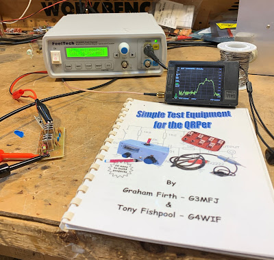
I've been meaning to try this for a long time.  Years ago Tony Fishpool and Graham Firth wrote about using a noise generator and a spectrum analyzer to sweep the bandpass of a filter. The idea here is to send very broadband noise into a filter, and then use a spectrum analyzer to see which frequencies make it through.   

I thought about building a noise generator like the one in Tony and Graham's book, but then it occurred to me that probably had one sitting on my bench.  Sure enough, a look at the manual for my cheap FeelTech function generator revealed that PRESETS 3 and 8 are noise generators.   I quickly pulled out a 9 MHz filter that Dean KK4DAS had given me, put the noise into one end and the TinySA on the other end.  Bob was quickly my uncle.  See above.  

More recently Tony G4WIF built a comb generator as a noise source: 

Thanks to Tony, Graham, and Dean.  And to the folks who developed the TinySA. 

Monday, October 25, 2021

Putting a Ceramic Filter in the "Mate for the Mighty Midget" Receiver


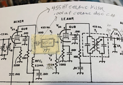
It is really simple.  I had one of the +/- 3kHz (6 kHz wide) 455HT filters on hand.  The spec sheets call for 2000 ohms at both ends, but looking at the schematic it appeared that I already had high impedance on both sides of the filter.  I put a .001 uF cap on the input side to keep the DC voltage off the filter (see above and below). This capacitor allows us to avoid the dreaded problem of electro-migration that is so nicely described by SV8YM here: 


Tasos also provides a good description of the innards of those little black boxes that contain ceramic filters. 

Once you get the filter in your receiver, you have to carefully place the BFO signal in relation to the filter passband.  I have trouble properly sweeping 455 kHz filters -- my HP8640B will not go that low.  Nor will my Antuino (I need to modify the code -- someone help me please).  I know the NanoVNA will do the job, but I just couldn't seem to get it to work.  So I went "old-school" and manually swept the filter using my FeelTech sig gen and my Rigol scope.  This gave me a rough idea of where the passband was.  I put the BFO on the low end of the filter passband, at 451 kHz.

   
With this filter the MMM RX has become a real asset.   The 6 kHz bandwidth allows for nice reception of both SSB signals and AM sigs.   I may try to use one of the +/- 2 kHz filters  (4 KHz wide), but so far I have not been able to find a source for this part. 

Monday, October 4, 2021

Scott WA9WFA's Mate for the Mighty Midget Receiver is WORKING! (Video)


Wow, Scott got his Mate for the Mighty Midget receiver to work and he is obviously overjoyed with the result.  All of us who have struggled with a homebrew project know just what this feels like.  And it is very cool that Scott got some useful guidance from Charlie Morris in far-off New Zealand.   Congratulations Scott.  I'm really glad you stuck with it.  

Scott's success comes at a good time:  Pete N6QW is building W4IMP's three tube "IMP" SSB transmitter (also from the 1960s).   I accept responsibility for naming Pete's project:  It will be known as "Pete's IMP" or, memorably,  "The PIMP."  For a look at Pete's rig go here: 

Scott had problems getting Lew McCoy's 455 kc crystal filter to work.  So did I.  It turns out that this is a very old problem, going back to World War II.  In Don Stoner's 1959 "New Sideband Handbook" on page 54 he writes of homebrew filters in the 400 to 500 kc range:  

"Inexpensive crystal filters constructed from war surplus FT-241 type low frequency crystals are very popular with the 'do it yourself' hams. These CT cut crystals have been plentiful and relatively cheap for a number of years and are in the hands of many Amateurs. The general run of war surplus crystals may or may not be good. Experience has shown that one out of four of these crystals are usually defective in one way or another." 

Stoner was writing just 14 years after the war.  Add another six decades to the age of these crystals -- often decades spent in musty basements -- and you can imagine the percentage of bad 455 kc FT-241  crystals increasing.  So I think Scott is wise to seek an alternative to McCoy's crystal filter. 

Scott's original build of the MMMRX receiver is just so nice.   In the video he says he plans to go back to it after he gets the expanded version fully functional.  He should definitely do that -- his  original version looks so good.  I think it is probably very close to working properly. 

Thanks Scott, and again, congratulations OM. 

Tuesday, August 24, 2021

Mythbuster Video #17 Boxing it Up, Tuning Filters, Tapping a Heat Sink, QRO Dreams....


I made a cabinet out of scrap packing material. I show how I tune LC filters by squeezing the turns on toroidal inductors. I tap a heatsink and think about more power for the Mythbuster.

Monday, August 9, 2021

Mythbuster Video #15 The Mythbuster Signal As Seen in the NA5B WebSDR


Mehmet NA5B has an excellent WedSDR receiver in Washington D.C., about 9 miles east of me. I often use it to check my signal quality. I think this video shows that the 10 pole crystal filter is working and is producing a signal with very sharp drop-off outside the 2.7 kHz passband. You should focus your attention to the passband (yellow vertical lines) near 3895 kHz. That's me.

Once, when I was describing my 40 meter DIGI-TIA to an SDR guy, he seemed surprised that I was using a -- gasp -- crystal filter. "Your skirts must be atrocious!" he said. My HDR sensibilities were deeply offended.

I had hoped that the 10 pole crystal filter would produce skirts so nearly vertical as to make my signal indistinguishable (in the waterfalls) from the SDR signals. At least at this low signal level, it appears to be working.

Saturday, August 7, 2021

Mythbuster Video #13 -- RF Power Amplifier, and Relay Switching Plan


In this episode we enter into the most fraught part of the construction project: the production of RF power. This is where amplifiers stubbornly turn into oscillators, and where components release magic smoke, or at least burn the fingers of hopeful builders.

I kind of ran out of room when I built the low-pass filters. But, thinking ahead, I wanted to have them on a separate board. And it is good that they ended up in the far corner of the rig.

Just going from one band to two bands adds to the complexity of the rig. I had to add two relays, one to switch the low pass filters, the other to switch the bandpass filters. I ended up with 5 DPDT relays in this transceiver. It was very helpful to have a plan and a diagram for the relays and all the switching.

It looks like each of the three RF amplifier stages provides about 15 db of gain -- about what I need to get to the 5 watt level.

Monday, August 2, 2021

Mythbuster Video #12 -- Bandpass Filters


The really cool part comes at the end when I put the scope probe on the output, then on the input of the bandpass filter.  Exciting stuff my friends! 

Monday, July 26, 2021

QST Repeatedly Got Sideband Inversion Wrong

It kind of pains me to do this. These articles are from a long time ago, and the author is an esteemed  Silent Key,  but the myth about the origins of the USB/LSB convention is still out there, and as a homebrewer of SSB gear I feel obligated to point out these examples of the error that that myth is based on.   

Last Friday, Pete WB9FLW and I were talking about homebrewing SSB rigs.  I recommended a series of QST articles by Doug DeMaw.  "Beginner's Bench:  The Principles and Building of SSB Gear" started in QST in September 1985. There were at least five parts -- it continued until January 1986. (Links to the series appear below.) I hadn't looked at these articles in years, but when I did, a big mistake jumped right out at me:  In the first installment, on page 19, Doug  makes the same mistake that he made in his Design Notebook:

"Now comes the conversion section of our SSB generator.  We must move (heterodyne) the 9-MHz SSB signal to 3.75-4.0 MHz. Our balanced mixer works just as it does in a receiver. That is, we inject the mixer with two frequencies (9 MHz and 5 MHz) to produce a sum or a difference output frequency (9 - 5 = 4 MHz, or 9 +5 = 14 MHz) If we are to generate 75 meter SSB energy, we must chose the difference frequency. We could build an 20-meter SSB transmitter by selecting the sum of the mixer frequencies. The RF amplifiers and filter (FL2) that follow would then have to be designed for 14-MHz operation.  In fact, many early two-band homemade SSB transmitters were built for for 75 and 20 meters in order to use this convenient frequency arrangement.  The use of upper sideband on 20 meters and lower sideband on 75 meters may be the result of this frequency arrangement (the sidebands become inverted when switching from the difference to the sum frequency.) " 

Those last two sentences are incorrect.  They repeat the "Myth," or the "Urban Legend" about the origins of the LSB/USB convention.  Contrary to what many hams now believe, with 9 MHz filter and a 5.2 MHz BFO it takes more than just switching from sum frequency to difference frequency to invert one of the sidebands. 

There are two conditions needed for sideband inversion to take place:  

1) You have to be taking the difference product (DeMaw got that right) 

2) The unmodulated (VFO or LO) signal must be larger than the modulated signal. (DeMaw and the ARRL obviously missed that part.  Repeatedly.) 

This is another way of stating the simple, accurate and useful Hallas Rule:  Sideband inversion only occurs when you are subtracting the signal with modulation FROM the signal without modulation. 

For DeMaw's claim to be correct, one of the SSB signals going into the balanced mixer would have to invert, and the other would have to not invert.  Let's see if that happens: He has the sideband signal being generated at 9 MHz and the VFO running around 5 MHz. 

9 - 5 = 4  But we are not subtracting the modulated signal FROM the unmodulated signal.  SO NO INVERSION

9 + 5 = 14   We are not subtracting at all.  SO NO INVERSION.  

Doug's convenient frequency scheme WOULD work if he'd just switch the frequencies of the filter and the VFO.  With a sideband generator on 5.2 MHz and a VFO around 9 MHz you do get the happy 75  LSB, 20 USB arrangement without the need to switch the carrier oscillator/BFO frequency.   That is what happened in the Swan 240, and that is what I have in my Mythbuster rig. I am listening to both 75 LSB and 20 USB without changing the carrier oscillator/BFO frequency.  My filter/BFO/product detector is set up for USB.   With this arrangement the 75 meter LSB signals DO invert, and the 20 meter USB meter signals do not, so both are able to make use of my USB BFO/product detector without shifting the BFO frequency. 

This error shows up again in DeMaw's the May 1989 QST article "A Four Stage 75-meter SSB Superhet" (reprinted in the ARRL's QRP Classics book).  Here he writes: 

"Should you want to cover both the 75- and 20-meter bands you can build a 20-meter version of FL-1 and band switch the two filters. As with the 75 meter only version, an IF of 9.0 MHz (Y1) is required. With this arrangement the 20 meter band will tune backwards from the 75 meter band, but upper- and lower-sideband reception will occur, as required, without changing the BFO frequency (Y2). This two band scheme with a 5-MHz VFO is an old one!"   NOTE: FL1 is the bandpass filter, not the IF filter.  

Doug's mistakes in this area may simply be due to the fact that he was more of a CW guy.  And this is something that is quite easy to confuse:  9 and 5 will get you to 75 and 20, but you have to make sure the VFO is at 9 if you want to make use of sideband inversion and avoid having to shift the BFO/ carrier oscillator.   I've made this mistake myself: 

In October 1993 I wrote to DeMaw about his Four Stage 75 meter SSB Superhet.  I think I was looking for details on how to put it on 20 meters.  As I recall, Doug wrote back telling me to just pick 20 meter values for the input bandpass filter.  Had I done so, I would have discovered that  -- for the reasons cited above -- this just wouldn't have worked on 20.  His BFO and filter were set up to receive LSB signals. That's fine for the incoming 75 meter LSB signals.  But on 20 -- contrary to DeMaw's thinking -- there would be NO sideband inversion. I'd be trying to listen to 20 meter USB signals with a receiver set up for 20 meter LSB.  

Did anyone else notice these errors.  Were there ever errata notices in QST on this?  

This is a reminder that you should take all technical articles and schematics with a grain of salt.  Many contain errors. We are all human, and this is a complicated subject with lots of details. 


Tuesday, July 20, 2021

Mythbuster Videos 8 and 9 -- The Old Military Radio Net plus "Zero Beat and The Vertical Skirts"


I like to listen to the Old Military Radio Net on Saturday mornings. This week I was listening with the Mythbuster receiver. The AM carriers provided a good opportunity to observe the effects of the steep skirts of the 10 pole crystal filter. We start at zero beat, with the BFO exactly on the carrier frequency. If I turn the VFO dial in one direction, I in effect move the passband in a way that puts the carrier in the passband. And it is no longer zero beat with the BFO, so we hear the heterodyne (the beat!). But if I turn the VFO dial in the other direction, the carrier is now outside the passband. Even though the BFO would produce a tone, we don't hear a tone, because those steep filter skirts are keeping the carrier out. We do continue to hear some of the sideband frequencies, because they remain in the passband. The very sharp drop-off of the carrier tone is a good indication that the steep skirts of the crystal filter are doing the job.


"Zero Beat and the Vertical Skirts" Sounds like the name of a Punk Rock band, doesn't it? Anyway in this video I explain what happened in Mythbuster Video #8 (above). I explain why we can hear the Old Military Radio Net carriers when I tune the VFO in one direction, but not in the other.
Designer: Douglas Bowman | Dimodifikasi oleh Abdul Munir Original Posting Rounders 3 Column