Podcasting since 2005! Listen to Latest SolderSmoke

Showing posts with label Si5351. Show all posts

Tuesday, August 15, 2017

International Brotherhood and the BITX Rigs

Bore and Heriberto's uBITX board
Nowhere is the International Brotherhood of Electronic Wizards more evident than in the work on the rigs designed by Farhan.  With the BITXs we see rigs designed in India that are now being built and modified all over the planet. Here are just a few examples of the global collaboration currently underway:

In Italy, Giuseppe is putting a BTX40 on 20 meters and making it a dual bander: 

Hi everyone, I just completed some tests on a Bitx40 running in 20 meters band. I addes the 20 as secondary band activate when needed. I apply some mods to switch to secondary QRPLab BPF filter centered to 20 meters and removed the C91 and C92 caps to work in USB. I done some RX tests in the weekend of iaru hf contest to listen some stations Active.
Here the issues registered:
1) the 20 RX sensitivity was a bit weak compared to 40 meters. I need to increase volume. ( To receive the 20 meters the vfo run to 26 MHZ, mybe some stage suffers of poor performance in this High frequency?)
I also tryed to increase the vfo over maximum allowed by raduino, using external buffer, but no results.
Please read the issues as: work but could work better!
2) the RX was not very clean: voice acceptable, but RX of Digital mode not very stable ( probably the cause could be the vfo shift for poor tuning control. I need to add lock function in firmware ...) Or interferences for free wire of connection.
3) Sometimes when switch on or change vfo to other band or mode, the bf amplifier start a self oscillation ...Resulting in my wife's screaming (the tests were also performed during the night!)
No tests was performed at the moment in TX because i need to install the LPF for the new band.
The firmware to make the test was a modified version of 1.17.1, few temporary mods to preset the vfo b to 14 MHz USB and correct the freq. Display.
These my tests.
Giuseppe Callipo IK8YFW.

Pavel is a young fellow in Cuba who is doing great things with the Raduino software: 

My Photo

Hi to all.
The code was updated, the change log is this:
v1.4Update to catch up with the features added in the Raduino v1.17.1 from Allard's code (CW SPOT and bug fixes)
  • Upgraded the operations instructions
    • More user friendly version with embedded images.
    • Add instructions for the S-meter, AGC and TX-power mods details and tricks.
  • Moved all images to its own folder "images".
As usual tips/bugs/comments/suggestions are welcomed, you can reach the code here: https://github.com/pavelmc/bitx40/
There is a inoffensive bug in the calibrate process, in which the actual calibrate value is not correctly showed in the LCD until you move the pot to adjust it, I'm working on it.
I'm slowly working in this direction now:
  • Bug removal in the calibrate function.
  • Finish the upgrade of the Si5351mcu lib with some improvements.
  • Adding CAT support via ft857d lib (https://github.com/pavelmc/ft857d):
    • Full compliance needs get rid of all the blocking delay() sentences and that need a structural/paradigm code change and a lot of testing (I have Fldigi/MixW/Hamlib to test, I think if that 3 works the rest will do it)
    • Moving to a library (yatuli: https://github.com/pavelmc/yatuli) for the pot usage, that will ease the process of implementing the CAT as almost all delay() calls are related to pot/clicks, so I'm on it.
    • Maybe implement a multiclick lib to optimize the code and make it more easy to understand.
 Any thoughts or whishes related to that?

I plan to make the CAT operation optional via a #define declaration as not all of us will/want-to use that.
73 Pavel CO7WT

Here we see Bore in Montenegro working on a uBITX designed in Cuba by OM Heriberto

Hi Colleagues
Bore Lezaic from Montenegro is working on the uBitx PCB designed by Heriberto -CM2KMK- from Havana, Cuba
Here some pictures he(Bore Lezaic) have posted in my FB wall.
Any question regarding uBitx PCB please send to Heriberto Gonzalez Mendoza at cl2kmk@frcuba.cu (please take care with the email address it is slight different to his actual call sign).
Qrv's
73's Jc

Bore and Heriberto's Board
Hidehiko in Japan was struggling with some LCD noise in his experimental BITX40.  I passed along the active filter circuit that I'd first seen in Roy Lewallen's Optimized QRP rig. 

To
BITX20@groups.io Jul 29 2017 at 4:22 AM I've finished the Bitx40 experimental project today. I added the AF-AGC and LM386 POP limitter with raduino v1.20.1 (Thanks Allard). And I also added the DuinoVOX for Digital Mode operation. It's a great radio but the problem is only the "LCD noise" when increasing the AF volume. hi... Can I reduce this noise? Or I have to use the analog VFO? Any suggestions welcome.
ja9mat Hidehiko

To Hidehiko JA9MAT: 
Very simple.  Just three parts.   NPN transistor (like a 2N3904) and a 47k resistor (collector to base) 100 uF cap (base to ground).   Vcc the collector. Emitter goes to the DC power input of the AF amplifier.  You can see my use of this circuit in the schematic in this blog post:
Look in the lower right, near the LM386 AF amplifier.  Click on the schematic to enlarge.  73  Bill N2CQR 

Thanks Bill,
Well I added "3-parts"(2N3904+47kohm+100uF) between the D18(1N4148) and the junction of R111(100ohm) and R1113(220ohm). The noise has absolutely gone!
ja9mat Hidehiko.
_._,_._,_

Saturday, August 5, 2017

Let's Give Jason NT7S Some Support!


Most of us are using Jason's code and his Arduino Si5351 libraries.   We now have an opportunity to help him continue to come up with the innovations that keep things moving forward on our workbenches.  

Consider becoming a patron.   Learn more here:  

https://www.patreon.com/NT7S

Thanks for all you do Jason!  


Thursday, July 6, 2017

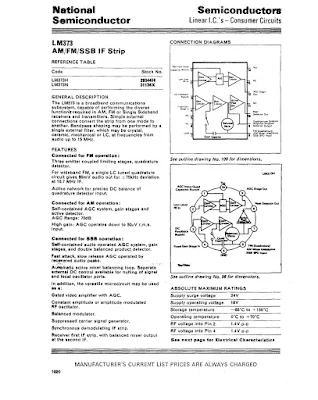
Another LM373 Rig - Pete Is Not Alone!


Sunday, July 2, 2017

AC9JQ's Mini Digi VFO/BFO Al Fresco with OLED (and noise test)


From Dean AC9JQ:

Just completed the VFO/BFO/Arduino/OLED module for my radio.  I also have the LPF, BPF and crystal filters completed and tested.  Next will be the audio amplifier and NE602 modules.  I will probably build one of the NE602 modules and test things out as a DC receiver.  My ultimate plan is to have the rig no more that 1"x3.5"x3".  I still have a lot of "stuff" to stuff into that size of box.  I'll keep you posted.


I have been able to contain the entire Arduino/Si5351/OLED into a small cube in the front.  The rest of the radio has to fit on two levels in the rest of the area behind the Arduino/Si5351/OLED.  I think I will build the audio section and on NE602 mixer and run it as a direct conversion first to vet out any noise or other problems.  Bill, that small coax that you pointed out will really help on this build.  I used a small piece as a power feed-thru and will use it to feed out the VFO/BFO signals, thanks again for that pointer.

I decided to test for noise on the TIA transceiver test bed.  See the video of the results.  Not too much noise.  I'm only using my indoor magnetic loop for an antenna.  Video is kind of sloppy, but taking off the antenna and turning up the volume shows how little noise is left in the system.  Now time to stuff the rest of the radio into the tight quarters.

I purchased OLED from ebay.......

They are nice and compact, although as time goes on, I'm sure they will be harder to read.  I'm hoping to have an alfresco version in a week or two.  I used much of Pete's code from the shirt pocket transceiver upgrade, modified the code to address the smaller display and add USB/LSB capabilities. 

73's  Dean AC9JQ

Saturday, June 3, 2017

My Organic Chip Rig with an LTSpice Schematic

CLICK ON IMAGE TO ENLARGE

This is a rig that came together through a process of Spontaneous Construction.  It started out with an innocent effort to get  an Organic Light Emitting Diode display to work with an Si5351/Arduino combination.   Then I figured I'd make a superhet receiver with it.  Then Pete said I should make it a transceiver.

Most of my earlier transceivers so closely followed the schematics of Farhan or others that it didn't really make sense for me to prepare a new schematic.  This one was different.  So I decided to prepare a proper schematic.  I tried a few of the free-ware CAD or drawing programs, but each of them had a learning curve at the entrance. So I turned to LTSPICE.  I have already climbed that learning curve.  

The results appear above.  Click on the image to make it bigger.   I'm sure there are errors in there.  And I think some of my parts choices might be less than optimal.  But it works well.

The filter was deigned with the help of AADE software.

The idea of using two NE602s with a filter between them came (I think) from the Epiphyte.

The band pass filters were designed with ELSIE software.

The RF power chain is mostly from Farhan's BITX40 module, with the pre-driver and driver modified for a bit more gain.  Farhan's amp is the most stable power amplifier I have ever used.  It hasn't given me any trouble, even at 20 Watts. Strongly recommended.

The microphone amp is derived from the 741 op amp circuit used in the (in)famous Wee-Willy DSB rig.

The receiver AF amp also comes from Farhan's BITX40Module.

Please let me know if you spot errors or have suggestions for circuit improvement.

A link to the .asc LTSpice file appears below.   Perhaps some brave soul  more skilled in LTSpice than I am might want to turn this drawing into an actual simulation.  Some of the parts (like the NE602s) have actual simulated components behind the drawings.  Others (like the relays and the LM741 and LM386) are just drawings.  But go ahead and flesh this thing out.  Who knows, it might come to life in the PC and start making QSOs on 40!

Here is the .asc file:  http://soldersmoke.com/NE602 Rig.asc


Sunday, March 26, 2017

An Si5351 Ham Sandwich from China (with video)

Ernesto Marquez alerted me to the offerings of CRKITS -- Chinese Radio Kits:
http://crkits.com/  Their Si5351-Arduino Pro Mini "sandwich" is quite interesting.  Here is a video on the device:


I must say, that nice little sandwich seems to be crying out for an organic slice of OLED.... How about it Adam?

While there is, of course, an enormous amount of electronics coming out of China,  I haven't seen much that comes from actual Chinese radio amateurs.  But CRKITS is the work of a real Chinese ham.   Adam Rong (Rong Xinhua) BD6CR seems like a very interesting fellow. From qsl.net:

About BD6CR/4

Adam Rong (Chinese name: Rong Xinhua), BD6CR/4 was first licensed in 1996 while in university in Hefei, Anhui province and now holds Class 2 Chinese amateur radio license (FCC Amateur General license equivalent). After graduation from university, he moved to Shanghai and call sign changed to BD6CR/4 in July 2003. Adam is now living in Pudong new district with his XYL and their son.
Adam holds a Master of Engineering degree in computer architecture and is an Engineering Program Manager in computer hardware industry. In spare time, Adam has written a lot about ham radio for magazines and papers, mainly about QRP, homebrew projects, APRS (Automatic Packet / Position Reporting System) and ham radio software applications. Adam has also translated two ARRL's books into Chinese for Post and Telecom Press in China, including part of the ARRL Handbook and ARRL's Low Power Communication: The Art and Science of QRP by Rich Arland, K7SZ.
You can contact Adam by email, or track Adam's real time position on Google map by clicking this link.

Saturday, March 25, 2017

N8NM's SR-16 Hallicrafters Tribute RIg

Bill,  Pete:

The rig is loosely based on the Hallicrafters SR-160 transceiver, since I'm using a RD16HHF1 in the final RF, I'm calling it the SR-16.   It's a tri-band rig covering 80, 40 and 20m.  Architectually, it's similar to Pete's JBOM, which is partially coincidental (thanks for sharing the article, Pete!)  The heart of the rig is the W7ZOI hybrid-cascode IF, a really slick circuit that really makes the rig a joy to use. 
Frequency generation is handled by the ubiquitous Arduino/Si5351 combo and a sketch based on Tom, AK2B's "Multi Function VFO", to which I added functions for selecting the appropriate bandpass and IF filters, generating CW, RIT, and dual VFOs (with split functionality), the state of which is saved in EEPROM when the rig is powered-down.
The rig's just about finished - I've got the remaining parts ordered and hope to have it on-the-air soon.
73! - Steve N8NM

Saturday, March 18, 2017

Channelized! BITX 60 with the Five Channels (with video)


Here's an update on my BITX 60 project.  The modified module is in the lower box.  An Arduino Uno and an Si5351 (this one with unreleased smoke) is in the Heath QF-1 box on the top.  I am using an Arduino sketch written by Don ND6T. It spits out the needed 17 MHz LO freq needed for each of the five 60 meter channels. You can scroll through the channels by just holding down the rotary switch interrupt button.

There is a move afoot to liberate from channelization about 15 kHz of the 60 meter band. When that happens, I'm ready to go -- I'll just reconnect the rotary encoder for the Si5351 and load some new code.  I suspect that by the time that happens, Don will have modified his code so that the 15kHz "tunable" segment will be integrated into the current program and will appear as one of the options as you scroll through the choices. 

For reasons that most readers will understand, I have resisted channelization for many years.  But here I am, channelized on 60.  It is not so bad.  I'm having fun listening to a new band, using a modified BITX, an Arduino, a bit of Heathkit and code from a fellow ham.   


Thursday, March 2, 2017

Jim WA7HRG's Beautiful Popcorn BITX

From the earliest BITX articles, Farhan has encouraged the use of discarded  cookie or candy boxes.  Jim's popcorn box is clearly in this tradition. There is also, of course, a connection to the idea of using simple "popcorn" transistors.
Popcorn Radio
by Jim Purvis WA7HRG

While celebrating Christmas and a Birthday at Disneyland in Dec., my wife and I enjoyed a box of popcorn during one of the many parades.  It was too nice a box to toss in the trash so I brought it home.  It kicked around the QTH a few weeks until I caught the BitX40 v.3 fever.  Wow, just enough room for the BitX and a few hacks, and the project was on. And a very neat way to remember our good time at Disneyland.

I decided on several hacks and mods and made a list.  In the end I settled for less. Hihi
1.       Switchable 5 or 20 watts out.
2.       Single power supply.  24 volt PA with a 13 volt regulator for the rest of the radio.
3.       Dual band. 40 and 20 meters.
4.       SSB and digital mode operation.  Built in audio interface and sound card.
5.       A tune function for antenna adjustments.
6.       On screen S-Meter.
7.       2.2” color TFT display.  Because I can display more information and it’s just cool. The Radino it came with was set aside for another project.

I had a 24V  5amp laptop power supply as the base supply.  I used two 7812 regulators in parallel and an aluminum plate heatsink and raised the common a little above ground for a 13 volt output.  I could then switch that between 24V for the PA.  Regulators get a bit warm when using them in the 5 watt position so most operation will be at 20 watts.

Dual band operation was soon abandoned simply do to space limitations in the box.  I had no room for additional BPF and LPF.

The audio interface not only provides ground isolation and level control between the PC and the radio it also provides a VOX operation for digital modes.  The digi software can provide the PSK (or other modes) audio on the left audio channel and a continuous tone on the right.  I use this for the VOX operation.  A ‘thumb drive’ size USB sound card provides the connection to the PC with just one cable.

Antenna tune function was provided by a version of Pete’s LBS method and I just used a small relay and a push button to activate PTT and to unbalance the balanced modulator.

The S-Meter proved problematic for me.  I might not have had it if not for help and advice from Pete.  It may not be accurate but provides a good relative signal strength indication.  And looks very cool!

The DDS is a quagmire of several different sketches and some of my own coding.  This was my first adventure into actually coding the sketch from (almost) scratch.  I am sure I am very close to the maximum times you can program an Arduino as my “Guess and Test” method of coding became very arduous. All switching of mode, power and other functions are done at DC allowing me to use that as inputs on the NANO to change DDS function and displays.

All and all I am very pleased with the way it turned out.  Not sure what I’ll do about losing 20 meters.  Hmmm guess I’ll just have to build another radio.  J


Front cover.  Upper Right corner is the Digi/SSB switch.  Tuning and vol are at the bottom. All controls and switches were located, sometimes in odd places, to retain the graphics of the box.https://ssl.gstatic.com/ui/v1/icons/mail/images/cleardot.gif

In the lid.  Upper left corner is the digi/SSB switch and across the top is the audio interface ckts.  TFT is in the middle Right.  Below that is the 3.3v level shifter and encoder.  On the heat sink are two 7812 regulators in parallel.  I raised the common a little above ground for 13v out. Far left is the vol control and S-Meter amp and det ckt.

The main chassis. Across the back left to right are power input, spk jack, mic/PTT jack, ant connector, and 5/20 watt switch. Far right is the PA heat sink. A 1x.5x4" aluminum bar.  It's what I had... Lower right corner is the tune push button and if you look close in the upper left corner of the main board is a mini relay glued to the board near the bal modulator. That unbalances the modulator and provides a carrier for antenna tuning. Upper left of the box below the power connector is the USB Sound Card for the PC interface. And a couple extra input wires I ended up not using.  Below that is the standard Nano and si5351.

Last but not least is the 2.2" TFT.  All functions power, mode, etc., are DC switched.  I also use that as inputs to the Nano for display changes. I sense the 12 v relay voltages and through a voltage divider to input pins.
It has been a fun project and I can continue to play with it, but I think its time to button it up and use it a little.
 It's back to my General Coverage Rec that I started but never finished.

 73  Jim WA7HRG

Sunday, February 12, 2017

Ken G4IIB's BITX Journey


The work of Ken G4IIB has been on this blog before -- he helped many of us make use of the amazing RTL-SDR Dongle SDR receivers.  He has recently turned his attention to the BITX40 Module and offers some great ideas for testing and for modification.  Ken's description of the smoothness of his audio adds a very evocative term to the SolderSmoke Enhanced SSB lexicon.     

Hi Bill, Pete

Many thanks for your respective responses to my plea for help in setting up SI5351 derived BFO to my BITX40 board. You were both on the money.


Pete suggested that I had too much gain in my HB amplifier from the SI5351 output to the modulator and indeed that proved to be true. Once sorted I also noted that I was getting extra hiss on switching to one of the sidebands as you pointed out Bill this proved to be due to incorrect placement of that particular BFO frequency.

These BITX40 boards that Ash Farhan has developed and released to the world wide community of Radio Amateurs are worth every penny. Because they are so hackable (not just the circuitry but now the Raduino code also) it means that you can tailor it to your specific specification and in the process you are likely to learn new stuff and make new friends. I describe my BITX40 incarnation and experiences below:

Upon first firing up the BITX I was getting quite a lot of mains hum from my PSU's (I thought that at least one of these PSU's was a quality item) but obviously not up to the job. I constructed a simple one transistor capacitor multiplier (this converted a humble 1000uF cap into a 1F cap) and the noise magically disappeared. By coincidence I note that Bill discussed this technique in a recent pod cast. Another advantage of this technique was that I got a 2V drop across the transistor so by running this on 13.8V I get 12V out so I run the PA section on un-smoothed 13.8V (this gives me 12 watts of RF out) and run the receiver section on the smoothed 12V output from the multiplier, happy days.

My thoughts were to turn my BITX into a multi band (several bands rather than all bands) rig and I figured that using high side mixing (running the VFO at 19Mhz (12Mhz + 7 Mhz) rather than the existing low side mixing (12Mhz - 7Mhz=5Mhz VFO)) would be a better option. For example running it on 17M would mean using high side VFO anyway. I also wanted the ability to be able to switch sidebands especially on the lower frequencies so that I could use the rig for Digital modes in my case this was to be achieved by coding the Arduino to run a BFO on one of the SI5351's clk ports.

I bought my BITX prior to the release of the Raduino so I had already commenced (with the aid of a new found radio friend and RF mentor) coding an Arduino VFO/BFO using a UNO and SI5351. Like I said at the beginning once you let folk know that you are starting on a new and interesting project you start to engage the more practical members of the ham community and they just want to get involved and help. Yet another good reason to buy a BITX . We used code originally developed by Jason Mildrum NT7S and Przemek Sadowski SQ9NJE and tailored it to suit the BITX40 and our requirements. This include high side VFO with frequency step adjustment and a BFO with long push BFO changeover. This meant that my BITX front panel should stay very minimalistic 2 knobs.
Getting the VFO to work was simple as the DDS socket was used and to better accommodate the high side VFO I modified the board by tombstoning caps C91 & C92.

Getting the BFO to work proved to be more problematic I was troubled with hiss and other noise. Words of wisdom from Pete Juliano when asked if I was doing something wrong were: " No –it is just that we tend to think our projects are like Lego type building blocks where everything mates and snaps together. Sometimes more is required". True Pete and that gives us the opportunity to learn new stuff!

To cut a long story short I found that the best place to connect the BFO was on the modulation transformer T4 thus bypassing the BITX BFO stage altogether. I was also getting hash noise believed to be emanating from the Uno. At this stage my after market Raduino arrived from India. I fired this up and noticed that I was not getting any hash noise from it. This pointed us to a coding problem and the LCD refresh was altered on our code and the problem disappeared. Below a picture of the module showing the BFO connections to T4 and the large heat-sink with the IRF510 insulated from it. Also shown is the capacitor multiplier and a glimpse of the Raduino in the foreground. Not the most elegant box but this is likely to change pending further refinements. It's still work in progress and this box gives me plenty of room.


The Raduino is a fantastic piece of kit for the money extremely neat and well thought out. The coding is comprehensive and innovative and works well. However, from an aesthetic and ergonomic point of view there were a few things that I personally did not like in terms of how it operates and performs. I could not get away with the potentiometer tuning, you can tune 50Khz of the band and then when you near the pot edge it increments/decrements and you can re-tune. I found this clunky to use and in addition the Raduino would hunt causing the last digit to increment then decrement causing an annoying warble on audio. In my opinion a Rotary Encoder would be better solution. On the plus side, although not mentioned on the Hfsigs web site the Raduino code does come with other functions such as changing sidebands by temporary high siding the mixer, a RIT, VFO B and CW tone. If you download and read the Raduino code from Github you will see this extra functionality which I believe you can make use of via extra switches (not supplied). The current Raduino code does not have any external BFO options as said it relies on the crystal BFO and temporally high siding the VFO to change from LSB to USB on 7Mhz.

The Raduino module itself is just too good and neat not to use. As I did not have the where for all to fully understand and amend Ash's code I decided to use the Raduino but to load it with the code that we have developed for he Uno and Addafruit SI5351 board. This would give me near conventional tuning via a rotary encoder, adjustable step sizes via quick push of the encoder switch and USB/ LSB switching via long push of the encoder switch by virtue of the SI5351 generating the BFO frequency. I have retained a copy of Ash's Raduino code just in case I wish to revert to it. I put a new header on the Raduino P3 connector so that I could connect a rotary encoder and use the 2nd clock output and then changed our code to run on a Nano. I had to add a correction factor in the code to cater for calibration differences in the SI5351's (in my case 1.21Khz).

As previously indicated I had a little trouble arriving at the correct BFO frequencies I found that 119940 and 119970 gave me LSB and USB respectively for my high side VFO (19Mhz) if you use low side VFO (5Mhz) then these would be reversed. We further refined these frequencies by injecting white noise into the mic amp and looked at each transmitted sideband on my RTL-SDR dongle via HDSDR (a useful piece of test equipment). By adjusting the carrier trimmer to show the carrier in the extended HDSDR spectrum display we could see how much to move the BFO frequency to best occupy the crystal filter pass band, see image below. This frequency adjustment being achieved by a coding change. The frequencies I consolidated on to cater for my particular crystal filter are 119941 LSB and 119969 USB. We then nulled the carrier back out. My audio is now as smooth as a maiden's inner thigh, trust me the image will follow!


So now I can get on and build an AGC and think about some sort of S meter. As for putting the BITX on other bands, whilst I now have a VFO capable of going anywhere, I would need to address band pass and low pass filter and switching arrangements. I may still experiment with this but, as pointed out by Ash in a recent pod-cast, the BITX single superhet design is not best suited to multi band operation but can be quite easily changed to operate on another single band. He also indicated that he was developing a dual superhet with consideration for multi band operation. Once released this might be a better option for multi-band use.

In the mean time folk should just get a BITX40, hack it to bits and share with us their customised versions.

Ken G4IIB


Tuesday, February 7, 2017

ZL1UEM'S Tiny OLED Si5351 Arduino VFO


Hugh ZL1UEM has come up with a very creative way to take maximum advantage of the small size of the Si5351 board, the Arduino, and the OLED display.  He even has the rotary encoder in there.  Look carefully -- he uses both sides of the board.  Very nice. Thanks Hugh!

Hi Bill,

First let me say that I have been an avid follower of the SS blog and podcasts since the days of your podcasts involving Mike KL7R.

Like many others I was tempted to purchase the $49 surface mount module from HF Signals.  As a keen home brewer I felt guilty about employing a prebuilt board but excused my decision on the grounds that I would build a DDS and other accessories myself.

In addition to follow the SS blog I also check Pete's blog regularly and was excited by his OLED VFO for the Bitx40.

I constructed it on a small double sided matrix board with plated through holes.  A bit of noodling led to the layout shown in the photos.  There is only one board with components mounted on both sides.  The board came to life on the first power up but the text spilled off the bottom of the display.

I assumed that the sketch that I had downloaded from Pete's blog was for a different OLED module.  I knew that he had also used a yellow/blue OLED, the same as mine, previously so emailed him requesting a sketch for this OLED.

I was taken aback when he informed me that the sketch I had was the same for both the dual colour OLED and the black and white one too.  Pete suggested that I swot up on the use of OLEDs generally and that perhaps I should first experiment with the text size to begin with.  He also offered some advice about the mapping of the screen.

I soon discovered that the text size was not the cause of my grief and that I needed to look elsewhere.

I first tried running the ssd1306_128x64_I2c sketch from the sample sketch folder and was rewarded with the message "Height incorrect, please fix Adafruit _SSD1306.h".  A search of the Internet revealed that I needed to edit the .h file and find "#define SSD1306_128_64" which was commented out and uncomment it and make sure that the other two options, _32 and _16, were commented out.

My next problem was how to edit the specified .h file.  I tried notepad but the text all ran together.  Another internet search revealed that Notepad++ was a suitable choice and it did indeed cut the mustard.

A reload of the sketch completely restored the display to full functionality.

All this may be obvious to many but it was all new to me and if I had not been prompted by Pete l would not have had learnt so much and would not have had the same sense of achievement when it all came together.

Many thanks to you and Pete for providing a focus for my hobby.

73's
Hugh ZL1UEM

Saturday, January 28, 2017

SolderSmoke Podcast #193: BITX 40, OLEDs, KWM-4, Noise Abatement


SolderSmoke 193   28 Jan 2017


Report from Pete on BITX 40 Session with California radio club.

Update on the BITX40 Module Revolution
-- Check out the BITXHACKS page.  Send in contributions.
-- BITX20 mailing list very active.
-- Raduino!
-- Interview with Farhan with W5KUB --   Eliminating the commercial gear.
-- BITX 40s on the beach in Australia.  FB

Bench Reports:

Pete:
-- Color Displays!
-- KWM-4
-- OLED MADNESS!

Bill: 
-- Fixing up the old HT-37   HT37 to HT37 QSO with W1ZB
-- Dabbling in VHF with Ramsey Aircraft band receiver.  NOT FUN.
-- Going all IC with Si5351 OLED NE602 rig.
-- BANDSWEEP
-- OLED Noise and the Active Decoupling solution.

Using LTSPICE as a diagnostic or understanding tool.

Of Waterfalls, Homebrew Rigs and Casual Critics on 40 meters. Words of Wisdom from W8JI.

LEXICON:  HAYWIRE   TOMBSTONE    BIKESHEDDING from Todd K7TFC

Some great recent interviews by Eric 4Z1UG:
Ian G3ROO  Origins of ROO   Regen at age 8
Hans Summers G0UPL     Balloons!   NO COMMECIAL GEAR
David White WN5Y          ELECTROLUMINESCENT  RECEIVER EXPLAINED
Rob Sherwood NC0B 

MAILBAG: 

Chris KD4PBJ's BITX 40 with improved stability
Jerry W0PWE built a DIGITIA!  Very nice.  Worked Keith N6ORS and heard me! TRGHS
Mike AB1YK's Al Fresco Scratch built BITX.  But give that LC VFO another chance Mike!
Steve N8NM 30 meter rig with salvaged CB LC VFO. FB
Keith N6ORS Franken SDR rig with parts from the 1980s.  FB
SKN Bandscan from Mike WA6ARA  I worked W1PID Jim!
What is Mikele up to?
Rocking Johannesburg and Kirghizstan via local repeaters:


Friday, January 27, 2017

When Bypass Caps are Not Enough: Active Decoupling

I was having a noise problem with my NE602 Si5351 OLED display receiver.   There was an annoying high pitched whine in the audio output.  The source was easy to identify:  If I reached in and unplugged the OLED display, the noise disappeared.  

Next I had to find out how the OLED noise was getting into the rest of the receiver.  It could have been through the SCL SDA or even the ground lines.  It could have been just through capacitive or inductive coupling from the display board itself.  A big clue came when I tried powering the display from a completely separate power supply: BINGO! The noise disappeared. So I knew the noise was going into the rest of the receiver through the Vc line that powered the OLED. 

I had been powering the OLED from the 5V regulator on the Arduino Uno. In an effort to isolate the noise, I put a separate 5V regulator in the circuit for the OLED.  No joy -- noise still there.  I then tried putting an RC low pass filter between the OLED and the 5V regulator.  Still had the noise.  Finally I remembered something from the AF AMP circuits of Roy Lewallen, Rick Campbell and Roger Hayward. ( I think Roy was the pioneer on this one.)  They all used an "active decoupler" between the first AF amp and the power supply line.   I confirmed that it was my first AF amp that was picking up the OLED noise.   I built the active decoupler (just three parts!) and the noise disappeared.  GONE! 

There are only three parts, but the way this circuit works is kind of complicated and not very intuitive.   There is a good discussion of how it works here:

www.facstaff.bucknell.edu/dkelley/elec351/Lab/elec351lab5_sp04.doc

Roy, Rick and Roger were using this circuit to knock down 60 Hz AC hum, but I found that my OLED noise was at around 200 Hz -- I figured (correctly) that the active decoupler would take care of this as well.   I think this little circuit can be useful in dealing with the kind of noise generated by the digi displays that many of us are now using.    

David Rowe has a really interesting analysis of this circuit here:
http://www.rowetel.com/?p=4781

Sunday, January 22, 2017

HB2HB: N6ORS, W0PWE (and me!)

This is so cool.  Jerry W0PWE has built a magnificent BITX.   With a digital VFO and Termination Insensitive Amplifiers, I think it qualifies as BITX DIGI-TIA #2.   Running it "al fresco" he was tuning around on 40 and he heard DIGI-TIA #1 (mine!).  As soon as he finished soldering in the power amplifier, he put it on the air and, in his second contact, worked Keith N6ORS -- Keith was running his MIN-X rig.  Clearly TRGHS. Great work Jerry!
Hello Bill,
Jerry here W0PWE in Iowa. I save up your podcasts and listen to them when I travel. A year or two ago you and Pete got me interested in the BitX and I finally took action. I have plenty of other
projects I should finish but boy was it ever fun to start a new one. This morning I soldered the
last part in my newly hatched Bitx, drug it over to the operating position and had two great QSOs
with it. See attached photo shows the rig as it was during those QSOs.

When I finished my first QSO with W9SX, Keith in WI N6ORS called me. He was running a multi-band Bitx he had built and we had a great HB2HB qso. Awesome!

My rig is scratch built, mostly SMT and generally follows the 40M schematic that Farhan has on
his HFsignals page. I am using the Kopski/Hayward TIAs though and I designed a 6 pole crystal
filter for it since 6 of the 10 crystals I bought were very similar when I characterized them
with my PHSNA setup. It uses the Adafruit SI5351 board and I modified a sketch that LA3PNA wrote for the Arduino. 

I designed and fabricated the boards for it using the software and process described by K7QO and
W5DOR. Toner transfer with the Hammerhill Gloss paper is working great. The heatsink on my IRF510 is a little light. I could smell the MOSFET warming up during a few of my lengthy transmissions with Keith.

Now the SWL report. While listening on the receiver portion of my Bitx last week I heard you on
7260 at about 0030Z. I think that was Tuesday or Wednesday. I wished I could give you a call but
at that point my PA was merely a few traces on the computer screen. Hope to hear you again on
40M.

73/72,
Jerry - W0PWE

Friday, January 6, 2017

NE602 Si5351 OLED "Whole Foods" Receiver

This is one of those projects that sort of just happened.  First I built an Si5351/Arduino synthesizer with a small OLED I2C display (program by Thomas LA3PNA -- thanks Thomas).  Tom Hall AK2B up in New York helped me get the Si5351 VFO and BFO going -- thanks Tom.  Then, over the holidays I decided to build a rig of some sort around the Si5351.  I started with a superhet receiver using an NE602 as the mixer and another as the product detector.  I power the NE602 with an 8 volt regulator from W8NSA -- thanks Jim.  I made a 4 crystal 11 MHz Cohn filter using crystals left over from a BITX project.  The software from AADE helped me design the matching networks to match the filter to the 1500 ohm impedances of the NE602s.   I built the circuits on a milled board sent to me by Pete Juliano N6QW -- thanks Pete!   I put a dual tuned circuit at the front end, going into a MOSFET RF amplifier.   For audio amp I have an LM386.  The whole thing is screwed down to a barbeque grilling plank from Whole Foods -- thanks Whole Foods!  (This seems appropriate -- the "O" in OLED is for "Organic"!)

It sounds nice.  I may eventually try to put some relays in to switch the NE602s and the filter around to make this a transceiver.

Friday, December 23, 2016

Big News! BITX 40 Module Gets Digi Side Car! Raduino!

A very nice Christmas present from Farhan in Hyderabad!   An Si5351/Arduino Nano VFO for the ALREADY AWESOME BITX 40 Module.   I'm really glad Farhan kept the digital stuff on a separate board -- it just seems like the right way to do it. 

Details on http://hfsigs.com


Wednesday, December 21, 2016

Armstrong, obsessed


Jerry AA6KI sent me a nice website about radio hero E. Howard Armstrong. It contained an image that seemed to cry out for a meme.  I couldn't resist.

Sunday, November 6, 2016

SolderSmoke Podcast #191 RIGS! REAL RIGS!, BITX40 Module, EMRFD, MAILBAG


SolderSmoke Podcast #191 is available:

http://soldersmoke.com/soldersmoke191.mp3

TRAVELOGUE AND FAMILY DOINGS:   Pete son's wedding, Billy's Birthday, Gonzalo safely home in the Dominican Republic, MORE BEARS IN THE SHENANDOAH WOODS

BIG NEWS:  EMRFD LIVES ON!   Three cheers for Wes and for Tom Gallagher of the ARRL.

BENCH REPORTS:

PETE:   FPM Rig.  Some Halli history.  A TRUE RIG!  Working Japan. 
             WITH 600 WATT LINEAR AMPLIFIER!!!!!!!!!!!!!!!!!!!!!!
               New FEELTECH  Sig Gen.  

BILL: Farhan's BITX Module
           Built to Mod, built to get you started in homebrew
           Very impressive.  BITX in miniature.  But completely recognizable.
           REMARKABLY stable.
           Farhan personally checking each one.
           Ladies collective doing toroids.  DONATION money bought them some Diwali candies!
           VFO Drift:  Will NP0 SMD caps and lower current help enough?
           My Analog VFO -- BANDSWEEP

QRPppppppppppp  with REX's Hamfest Buddy.   Thanks Rex and Bob Crane.

HB2HB with KW4KD

MAILBAG
Jan's Netherland Mate Mighty Midget
Charlie's Kiwi DSB
Steve, Donald Fagan, and Jean Shepherd
Rob VK5RC repairs Tek Tube 'scopes
Colin M1BUU Si5351 superhet
Denis Klipa and NRL 3538
Jonathan M0JGH Wizard of Wimbledon Matchbox rig
JH8SST Simpleceiver
Peter Parker Vk3YE Reviews Book
Peter GW4ZUA Welsh LBS
Michael Rainey helping hobbyist in Germany with tuning forks.


Tuesday, November 1, 2016

It's Ugly, But It Gets You There: Pete's Latest Rig

That, my friends is an extreme  example of what we mean when we use the word "rig." This magnificent machine sent Pete's melodious voice across the mighty Pacific several times during the recent CQ WW contest. 

Pete wrote to Jun:

Hi Jun,
 
This weekend is the CQ World Wide SSB contest and I just worked three JA stations on 40 Meters. The time 1400 UTC. I must confess that I was using 600 watts to my droopy dipole but they came back on the first call. So there are paths open and perhaps 600 watts was overkill but the timing seems like it works for a good path to the west coast. Along the way I also worked a station in Hawaii (KH6).
 
See if you can find some 813 tubes as they make a great grounded grid linear amplifier tube and a pair will give you 600 watts. see http://www.ohio.edu/people/postr/bapix/813amp.htm
 
The rig I was using is shown below. The mainboard came from a Hallicrafters FPM 300 (late 1960) to which I added the Rx Tx Mixer (SBL-1), my stock 2N3904 bi-directional amp board, the 2N2222 + BD139 driver stage using the EMRFD circuit and a 2SC2075 final which gives about 3 watts. This in turn drives an intermediate SS amp to 100 watts and then the SB200 to 600 watts. The FPM 300 used a 9.0 MHz IF frequency.
 
Of course no rig today from N6QW would  be complete without a Si5351 and the color TFT display. Rounding this out is an LM386 audio amp stage. Cosmetically the rig doesn’t look pretty but sure works well.
 
73’s
Pete N6QW

(The comments about the 813s are kind of SHOCKING, coming from a member of the QRP Hall of Fame!)


Friday, October 28, 2016

Another Great DSB rig from New Zealand


So many great Double Sideband projects come from Down Under.  There are the various versions of the famed ZL2BMI rig.   And Peter Parker VK3YE has long been the acknowledged guru of DSB. In fact, Peter sent me an enthusiastic e-mail about the new ZL DSB rig pictured above -- his e-mail arrived before the message (below) from the intrepid builder.  I detect a bit of the "Tucker Tin" influence in this rig. (But perhaps this one is more Tupper than Tucker!)  Charlie's work has graced out blog posts before: http://soldersmoke.blogspot.com/search?q=zl2ctm
Be sure to check out his video:   https://youtu.be/JsAuWGkyvmE   (and below).


Hi Bill.

You asked recently on the podcast for listeners to let you know what they had on their work bench. Well I’ve been working on a tramping (hiking) radio, which is now complete. It’s a DSB 5W rig designed for 80, 40 and 20m, as well as our New Zealand mountain safety radio system. I designed everything in LTSpice as was suggested by Pete, N6QW. That was great, as I could ‘desolder’ components with the mouse and instantly see what impact it had on the output. An amazing tool that’s free! I highly recommend it.

Once again I’ve used upside down strip board for each stage, which are tacked down onto an un-etched copper board (earth plane). That seems to work really well for me.

The rig uses an Arduino mini driving a small OLED screen and a Si5351 DDS. The Si5351 is going straight into a SBL-1, which seems to work fine too. The AF strip is a 2N3904 before a LM386, which has enough drive to run a speaker. The TX amplifier is a three stage one with shielding between each stage. It’s made up of two 2N2222A stages followed by a BD139. That in turn is followed by three simple filters, one each for 80, 40 and 20m.

All-in-all it works really well. I’ve uploaded a quick video at https://youtu.be/JsAuWGkyvmE

The next project will be a proper SSB rig using a crystal filter salvaged from an old Codan 7727. Like this one, it will use an Arduino and a Si5351.

Finally, I am certainly no expert in homebrew, but I hope my ‘dabbling’ will help inspire others to pick up the soldering iron and give it a go. If I can do it, then anybody can! There is certainly a great sense of achievement to operate a rig you built yourself.

Regards, and thanks to you and Pete for all your inspiration.

73’s
Charlie
ZL2CTM


Designer: Douglas Bowman | Dimodifikasi oleh Abdul Munir Original Posting Rounders 3 Column