Podcasting since 2005! Listen to Latest SolderSmoke

Monday, June 13, 2016

Inside a Millen 61455 IF Transformer


I found this in my junk box.   I've put it in my old Mate for the Mighty Midget receiver, in the place of the Toyo  CM455 crystal-mechanical filter (which I found to have excessive insertion loss).  I think its very cool how they squeezed two variable caps into that little can.  Designed in 1956.  Works great.  Note the promised passband: 4.7 kc at 6 db down.  Not bad for an LC device.
Here is the spec sheet:


Saturday, June 11, 2016

Bob Crane Interviews Eric Schwartz of Elecraft About the New KX2 (with Si5351!)


Our ace correspondent Bob Crane W8SX caught up with Eric Schwartz WA6HHQ of Elecraft at the FDIM event n Dayton last month.    Here is Bob's interview with Eric:  

http://soldersmoke.com/WA6HHQFDIM.mp3

Pete and I were very pleased to see that Elecraft made use of our beloved Si5351 chip in their amazing new KX2 rig.   Check it out:


You can click on the diagram or see it directly on page 62 of the manual at this site:

Here's the KX2:


Three cheers for Elecraft!  Three cheers for Bob Crane! 


Thursday, June 9, 2016

Excitatation! The Inspiring Knack Story of N3IC

Steve Silverman sent me this link.  This web site has been getting a lot of attention from the solder melting community.  And justifiably so.    Behold (above) the first transmitter built by Robert Glaser,  now N3IC, circa May 1969. The chassis and front panel were made from flimsy printing press sheet metal.  Note the key (as in lock and key) switch that the OM put on the front panel -- he took his responsibilities under FCC regs quite seriously.   My favorite part of this rig's story is that when he got it done, he didn't have the two 6146s for the final.  So he just took a capacitor and used it to connect the driver tube to the output network. Brilliant!  With that arrangement he made his first contact.  No wonder he labeled it "Excitatation!"  It was clearly more exciting than your standard excitation.  

Those TV power transformers look very familiar.  I was using similar devices to build a power supply for an HW-32A a few years after Dr. Glaser built this rig.  It's a wonder we survived.

FB.   Check out his site.  It is a wonderful catalog of all the stuff this very prolific builder has made over the years:

Ham project here:

A broader range of projects here:
   

Monday, June 6, 2016

Spectacular Solar Weather


This amazing picture was taken last night at the Bharati Indian Base Station in the Larsemann Hills of Antarctica. The researchers there report that the aurora was so bright that it cast shadows.

Yesterday I was having a nice 40 meter SSB contact with N3TDE.  Rich is 179 miles away, in Pennsylvania.  At 1650 UTC, his signal very suddenly dropped into the noise. 

The purple lines along the bottom of the chart below probably explains both the aurora and the abrupt end of my 40 meter contact.

GOES X-Ray flux plot

Sunday, June 5, 2016

Re-purposed Computer Power Supply Box Provides a Home for a BITX Transceiver


Jaydip VU3JOJ came up with a really inventive way to box up his new BITX transceiver.  Nicely done. I especially like the way he put the speaker  in the space intended for the fan. Very nice.

This appears to be one of the new BITX 40 meter "modules" described in yesterday's blog post.  FB!  How fortunate the new board fits in the power supply boxes.  That's very lucky.

You know, I had an old computer power supply in my hand  just yesterday.  I almost threw it out.  Obviously that would have been a mistake.

Today was a BITX day.  Using my BITX DIGI-TIA on 40 I had a long QSO with Rich N3TDE.  Rich has a BIT20 built from a Hendricks kit acquired at Dayton.  He takes it with him on the Appalachian Trail.  


Saturday, June 4, 2016

A Really Nice Project: Farhan's BITX40 Module

Wow, that board is a thing of beauty.   And the story behind it is even more beautiful. Our friend Farhan took his famous BITX circuit, shifted it to 40 meters, and put the whole thing on one small board. It is now a module, but a module that makes up an entire SSB transceiver.  The idea is that this module can provide a base for expansion and experimentation.   You can add a digital display.  Or a (gasp!) digital VFO.  Or an RF amplifier.  Or more bands.  Or all of the above.  It is a very cool idea.

Here is the most beautiful part:  In an effort to help people who need help, Farhan has arranged for a collective of women to assemble the boards in their homes. They needed work, and Farhan gave it to them on good terms.  Bravo Farhan!

In keeping with the earliest purpose of the BITX rigs (simple transceiver for Indian radio amateurs) this board is currently only available in India.  

Check out the site:

The circuit description is especially good:

Friday, June 3, 2016

Ryuu's Receiver (Superhet using Si5351 and Color Display with IF at 10.7 MHz from JA2NKD)


The influence of Pete Juliano is spreading far and wide.  Those little color screens attached to Si5351s seem especially popular in Japan.  Above is the receiver of Ryuu JA2NKD.  Below is the schematic.  Click on it for a better look, or use this link:
http://ja2nkd.c.blog.so-net.ne.jp/_images/blog/_206/JA2NKD/7MHzcolorLCDSchematics.jpg?c=a1


Ryuu's blogs are here : http://ja2nkd.blog.so-net.ne.jp/
and here: http://ja2nkd.blogspot.jp/
They are in Japanese.  Google Chrome does a poor job at translating them, but you can get the gist.  In any case the pictures are great and the schematics are understandable by all of us.  Thanks Ryuu!


Thursday, June 2, 2016

Manhattan-style Vacuum Tubes: "An Evolution of Thermatron Homebrew Techniques" by Grayson Evans


Grayson Evans was at Dayton.  Scheduling problems prevented him from being interviewed by ace correspondent Bob Crane, but Grayson was kind enough to e-mail us the essence of his presentation.  And it is really wonderful.  He brings the advantages of the Manhattan construction technique (fast prototyping, all components on the same side of the board, easy modification) to the world of tubes (aka valves or, as Grayson prefers, thermatrons).  We also see in Grayson's work an admirable willingness to bridge the digital-analog design, to bring into his rigs the best of the old and the new.  Thanks Grayson!

Grayson writes:

An Evolution of Thermatron Homebrew Techniques

For a long time I have been trying to develop some techniques to prototype Thermatron projects as easily as the typical “Manhattan style” solid-state construction.  Thermatron projects you see now-a-days still use the traditional technique of mangling aluminum-drilling and mounting everything to a “bud” style chassis. This just takes too much time and my projects always look disappointing.

Fortunately, around two years ago, Rex Harper, W1REX, came to the rescue after hearing an earlier talk of mine and developed a set of thermatron socket pads. The MeTubes panel from QRPme consists of 10 prototype pads for thermatron sockets. The panel has v-scores for breaking the panel into single tube pads. The panel has pads for mini 7 & 9s, octal, compactrons and acorns. Awesome.


The best sockets to use with the pads are PCB style.  These provide a large pin area to bend out and solder to the pad (see photos). 


I pre-mount a dozen or so of the 7-pin and 9-pin sockets on MeTube pads so I have them ready to go when prototyping. The “crude” example below shows and 7 and 9-pin socket on one of my prototypes.  I think this was a microphone amp for my AM transmitter.  Pardon the mess.


The nice thing about the pads is that they provide plenty of room to tac solder lots of parts to a single pin–easy to add or remove parts.  This is a lot easier than using the traditional tube socket pin. 

Prototyping thermatrons in this way is FAST.  No more punching out holes to hold thermatron sockets in aluminum chassis!

But it is still nice to be able to have the thermatron on the “top” of the board and the components on the “bottom” of the board.  To do this and still use the MeTube pads, the thermatron has to be mounted on the other side.  I did this by mounting the socket through the MeTube pad.  This requires making a hole in the center of the pad to pass the socket through and then soldering the pins in the usual way.  This is way easier with PC mount thermatron sockets and make a very nice installation. 


This technique has some great advantages over using the traditional socket with pins.  The pad has a lot more room to mount components to each pin.  Normal thermatron socket pins are difficult to attach more than two wires and it’s a bit more difficult to get a good solder connection.  The pads are easy to solder to and allow components to be easily attached in any direction since the “socket” is now flat.


It is also easy to attach the socket/pad to a copper clad board.  The same hole must be made in the copper clad board to pass the top of the socket through, then the pad is superglued to the board in the regular way.  


This is another example of “right side up” thermatron mounting on a prototype test board for crystal filters.  I mounted a small “plug board” (not sure what you call these things) in the center to allow me to easily swap filter components.  Notice the acorn thermatron soldered direct to the pad.  The board works great, the filter design sucked.  I gave up.  Maybe too much distributed C.


I used this technique, combined with Roger Fell’s idea of using inverted aluminum chassis, to build my latest project, a QRP AM/CW transmitter.  I’ve been wanting to try out a few new ideas and this seemed like a good project to try them on.  I also wanted to build the transmitter in modular “blocks”, interconnected in a similar way to Rogers. It worked pretty good although I am still trying to get the thing to work right.  Even new construction techniques can’t cure my screwups.  BTW, the ANALOG VFO is ROCK SOLID.  +/- 10 Hz over 30 min.   Even I was impressed.  The Hartley oscillator is the best circuit for thermatron circuits by far.


I’ll send an update when I get it fully working on AM and CW.
73,

Grayson
TA2ZGE


Wednesday, June 1, 2016

JH8SST Build's Pete's Simpleceiver (video)


Jun JH8SST made this nice video about his version of Pete Juliano's Simpleceiver.   I like the approach of putting the stages on separate boards, but perhaps Jun could have made things easier by using Manhattan-style construction on those boards.  And of course I like the breadboard-style aluminum sheet.  FB Jun.  

Jun writes:

I've built a simpleceiver, which is a modified version.   My first main board didn't work because of several problems, and that's why I decided to divide the board into several separated PCB's with some circuit modifications.
 
RF and Mixer stages are original, but I employed an 8pole 9MHz ladder Xtal filter.   The J310 X 2 is used in IF amplifiers, but load resonant circuit is modified to use a type 10K coil form and a ceramic capacitor.
J310 product detector is original and built on a tiny PCB, as shown in attached photo and YouTube Video.
 
This modified Simpleceiver has high sensitivity and more than enough gain. I needed to reduce RF/IF gain to eliminate product detector distortion caused by stronger signals.
 
This simpleceiver works really nicely.
 
I'm going to re-modify it to make it as original as possible.
 
The block diagram is:  J310X2 RF-DBM-9MHz 8 pole X'tal Filter-J310X2 IF-J310X2 IF-J310 product detector-AF μA741-AF LM380 with NFB.
 
I'm going to re-modify it as:  J310X2 RF-DBM-J310X2 IF-12MHz 4 pole X'tal Filter-J310X2 IF-J310 product detector-AF μA741-AF LM380 with NFB.
 
I'm also going to add an AGC system using a modified W1FB AGC circuit.
 

Tuesday, May 31, 2016

NP0 Is the Way to Go!

Much to the consternation of Pete "Digi" Juliano, I have been working on analog LC VFOs for simple superhet receivers.   As described in earlier posts, I recently converted an old Barebones CW superhet to 40 meter SSB.   At first, the VFO (2 -2.3 MHz) was not stable enough -- it would slowly drift in frequency. ("We have a solution for that," chuckled Pete.)   My first effort at stabilization involved replacing the toroidal coil.  The material in the core is sensitive to temperature changes and this can lead to instability.  I found my traditional cardboard tube from a coat hanger, and made a coil of the needed inductance (you can see it in the pictures).  This yielded some improvement in stability, but it was still drifting.  

Next I tried taking out all the silver mica and disc ceramic caps in the LC circuit of the oscillator and replacing them with NP0 ceramic caps.  The feedback caps are in the box below the tuning cap, but you can see some of the little NP0s on the outside of the box, connected to a rotary switch.  This serves as the equivalent of variable "Bandset" variable cap, with the tuning cap serving as the "Bandspread."  I have seven switch positions, each covering about 40 KHz (with some overlap).  This gives me all of the phone band and the bottom 30 kHz of the CW band.  

Switching to NP0 caps really did the trick.  The receiver is now very stable. When I told Farhan about my VFO woes, he mentioned that he'd had very good stability results with surface mount caps.  I wonder if this success has more to do with those caps being NP0 than with their surface mount configuration.  

Here is a good description of NP0:


NP0 Ceramic Capacitors are single-layer ceramic capacitors made from a mixture of titanates.
A NP0 ceramic capcitor is an ultrastable or temperature compensating capacitor. It is one of the most highly stable capacitors. It has very predictable temperature coefficients (TCs) and, in general, does not age with time. 
NP0 stands for negative-positive 0 ppm/°C, meaning that for negative or positive shifts in temperature, the capacitance changes 0 part per million, meaning that it has a flat response across a wide range of temperatures; the capacitance of the NP0 capacitor stays constant (at the same value) despite variations in temperature.  

From: http://www.learningaboutelectronics.com/Articles/What-is-a-NPO-ceramic-capacitor

But I think it is a stretch to claim that these marvelous caps do not "age with time!"  That would be a really astounding property of the titanium dielectric.  That would be a Negative-Positive Zero FLUX capacitor, right?


Monday, May 30, 2016

Movie Review: "The Man Who Knew Infinity" FIVE SOLDERING IRONS


My wife and I went to see this flick about the mathematician Srinivasa Ramanujan.  It was filmed at Trinity College, Cambridge -- if you look at the dedication to "SolderSmoke -- Global Adventures in Wireless Electronics" you will see a picture of my kids at Cambridge.  Alas, that picture was taken at Kings College, not Trinity;  nonetheless, the Cambridge connection got us interested.  Then there was the Indian aspect of the story, which is very intriguing.  There was also the "amateur makes good" angle that all of us should, I think, find very encouraging.

The movie did not disappoint.  We really liked it.  The presentation of the cultural clash was very well done.  Elisa told me that as she watched Ramanujan struggle with England,  she found herself wanting to tell him,  "You are just going through culture shock.  Be patient!  I've been through this many times!" They included just enough math to give the viewer a sense of what Ramanujan was working on. 

I got a real kick out of one scene in which old Professor Hardy, seeking to motivate young Ramanujan, took him into the Wren Library and showed him the manuscript of Newton's Principia. I had seen the same manuscript in the library of the Royal Society in London -- they had take it out on the occasion of the visit to the library of Stephen Hawking and NASA Director Mike Griffin.  They also had on the table the reflecting telescope that Newton himself had made.   That was quite a day.

Great movie.   I give it the coveted rating of five soldering irons.     

More about Ramanujan here:
https://en.wikipedia.org/wiki/Srinivasa_Ramanujan

Sunday, May 29, 2016

Great "QSO Today" Interview with H.P. Friedrichs AC7ZL -- "My nature is to build."


Eric 4Z1UG has a really wonderful interview with H.P. "Pete" Friedrichs AC7ZL.   Pete is the author of "The Voice of the Crystal" and "Instruments of Amplification."

I sat in the shack this morning with a cup of coffee, mesmerized by the things Pete was saying.  I actually took notes.  Some highlights:

-- In describing his zeal to avoid the use of store-bought components, Pete acknowledged that there are limits to this.  But then he revealed that his limits are different than those of even the most fundamentalist of homebrew fundamentalists:  "Well, I'm not going to mine my own copper."  Don't worry Pete -- no one will call you an appliance operator if you use store bought wire.  

-- On the same subject, when describing his homebrew diodes for crystal radios, Eric asked Pete why he didn't just go out and buy a Germanium Diode.  "That would be cheating," replied Pete.  Indeed.

-- "Obsolete technology often gets short shrift."

--"My nature is to build."

Check out the podcast here:

http://www.qsotoday.com/podcasts/ac7zl

Saturday, May 28, 2016

HOMEBREW HERO: REX HARPER W1REX AND THE WORLD'S BIGGEST BUILD-A-THON

Rex, shortly before questioning by authorities
Wow, Rex Harper W1REX deserves some sort of big award.  I hereby grant him the coveted Brass Figlagee with Bronze Oak Leaf Palm, but that is clearly not enough.  Rex spent a month of 20 hour days putting together kits for the Four Days in May QRP event at the Dayton Hamvention.   The results were spectacular:  246 hams succeeded in building QRP transmitters, and they all did it in under 70 minutes.   

Just as impressive as the results were the ways in which Rex overcame the technical and organizational hurdles prior to the event.  You can read all about this in Rex's excellent write up:
http://www.qrpme.com/docs/FDIM%202016%20Report.pdf

The OFFICIAL SolderSmoke Correspondent at Dayton was once again our friend Bob Crane, W8SX.  Bob caught up with Rex and somehow managed to get him to stand still long enough to do this interview:

http://soldersmoke.com/W1REXDaytonInterview.mp3

And it was very nice that Rex did this as a tribute to Dave Ingram K4WTJ whose magazine articles about simple QRP rigs inspired many of us.  Years ago, right after completing a homebrew QRP transceiver, I talked to Dave on 30 meter CW and told him that his articles had helped motivate me to build. 

Finally, no SolderSmoke post about Rex would be complete without a repetition of the video showing him transferring the prodigious mojo of the original Tuna Tin Two into my BITX-17 transceiver.

Friday, May 27, 2016

Pete's Beautiful New Blue Rig


A thing of beauty.  

Read about it here:   http://n6qw.blogspot.com/

Thursday, May 26, 2016

Listening to New Zealand on the Barbados RX via the Gray Line (40 meter CW)


John: 
For the last couple of mornings you have been coming in quite strong on 40 meters around dawn here.    Attached is a short video from today.  I am listening with a homebrew superhet receiver:
73  Bill N2CQR

Hi Bill,
Thanks for sending the video clip.
It’s really made my day!
I’ve sometimes wonder what I sound like at DX now I know.
The IC7410 sounds quite respectable and the sending is reasonably decipherable.
Interesting about the receiver.
The signal seems to stand out well from the noise.
Really well done. But then that’s what ham radio is all about.
We all enjoy radio and  we all like to enjoy the various aspects to the hobby.
Modes, antennas ,QRP whatever.
It’s great fun.
It would be good to have a QSO. perhaps some time soon?

Thanks again,

Very Best 73,
 John ZL1ALA

Wednesday, May 25, 2016

Swedish Michigan Mighty Mite Beacon Project


sTef DL1FDF/VY1QRP alerted us to this multi-band Michigan Mighty Mite beacon project out of Sweden. They certainly have some fine looking rigs! 

Check out the reports:
http://www.radiorud.se/fyren.php


Tuesday, May 24, 2016

Audiophoolery


Hi Bill:
 

   I remember reading an outraged letter in a stereo magazine back in the 80's, right after CD's came out.  The writer had condemned a particular CD player for having a single digtal-to-analog converter that was time-shared between the two channels, consequently inducing an "unlistenable" phase error in the audio.
    An engineer (and I hope a ham!) wrote in to observe that this was indeed correct, but helpfully noted that the phase error could be corrected by moving one of the speakers about a half inch farther away from the listener. That's noodling!  :-)
And you might enjoy this article:
...Some audio scams are so blatant you wonder how anyone could fall for them, like a replacement volume control knob that sells for $485. The ad copy proclaims, “The new knobs are custom made with beech wood and bronze … How can this make a difference??? Well, hearing is believing as we always say. The sound becomes much more open and free flowing with a nice improvement in resolution. Dynamics are better and overall naturalness is improved.” ...
  James Randi, magician and hoax-buster, had a standing offer of $1M to some makers of "paranormal" audio equipment, like $700/foot cable, if they could prove it was better in blind A/B testing.  Nobody took him up on it.

 73,
  Bob

Saturday, May 21, 2016

SolderSmoke Podcast 187: 2nd Anniversary N6QW. Dayton. Bench Reports. Mailbag


SolderSmoke Podcast #187 is available:

http://soldersmoke.com/soldersmoke187.mp3

Second Anniversary of Pete Juliano's arrival on the SolderSmoke Podcast.

Dayton and FDIM underway

Bench Reports:
Pete:
-- Repurposing old Circuitry
-- Pete's small Display
-- New Transmitter
-- LBS in Japan and at Dayton

Bill:
-- S38-E   The lipstick has worn off.
-- Reduction drive for the Mighty Midget's Mate
-- Back to the Barbados Barebones Receiver:
    Which LO to use for 40 Meters with a 5 MHz IF? 
    Sideband Inversion and "Lower Sideband" filters.
    Eradicating WWV with parts from AA1TJ
    Improving VFO stability
    A bandspread/bandset arrangement with fixed caps
    Soul in the Old Machine

"The Amateur is FRIENDLY..."

MAILBAG


Thursday, May 19, 2016

XQ6FOD -- A GREAT Knack Story from Chile


Greg VK1VXG sent me this link.  I had a blog entry on this a few years ago, but I didn't do it justice.  This is a truly amazing and inspirational knack story, the story of Manfred, XQ6FOD. So many lines from this page resonated with me.  For example:

I always regretted having disassembled this radio. It was so nice, so compact... Everything was hand made, there was not a single right angle in it... I felt like a murderer after destroying it. But, I needed the parts...

I designed this thing during a family summer trip into Chile's beautiful deep south. The VFO part was designed on Chiloe Island, the IF and receiver circuit took shape at Futaleufu, Rio Cisnes, Puerto Aysen and Coyhaique, while the difficult RF power amplifier work was done on the return trip via Bariloche in Argentina. So this is an international design!  Once back at home, for the first time in my life I did a thorough computer simulation of the whole thing. I hacked around the program for two weeks, and then my poor Atari had to spend another two weeks crunching numbers. It found some potential problems. I improved gain distribution, corrected mistakes, and then went straight to designing the printed circuit board, without doing any real-world test.

Check it out:


Monday, May 16, 2016

Oz QRP2QRP From Mt. Bullfight, Pyramid Hill, and Melbourne's Chelsea Pier


Saturday, May 14, 2016

A Lot of Soul in the Barbados Receiver

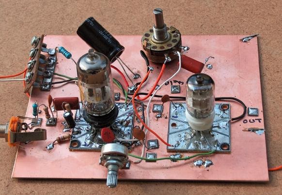
After a rather frustrating period working on the Hallicrafters S38-E, I decided to do something different, maybe work on something that isn't known as a "widow maker."    So pulled off the shelf an old Doug DeMaw Barbados Superhet Receiver.  "Barbados" sounds much nicer than "widow maker."  This design and this particular receiver have quite a history: 

-- DeMaw presented the receiver in the June 1982 issue of QST.  It uses six 40673 dual gate MOSFETS, an op amp for the audio, and a 250 Hz crystal lattice filter at 3.579 MHz using (YES!) colorburst crystals.  The local oscillator was a VXO. Doug's was for 20 meters, but his article provided a lot of info on how to put it on other bands.

-- I built one in 1997, building it for 20 CW.   That project is described here:

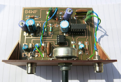
-- Sometime around 2000 I bought another one.  This one had been built on a FAR Circuits board by Dale Parfitt, W4OP.  Dale had used 5 MHz rocks for the filter and had used a varactor tuned circuit for the LO (with a DC-DC converter to increase the range).   I put it aside.  It sat on shelves in several countries for a number of years.  (I even have a THIRD one, a partially stuffed board that Michael Hopkins (the guy who wrote those great stories about Frank Jones coming back to life to retake the 5 meter band)).

-- I started working on it again around 2005. We were in London by then.  I put it on 17 meters using a capacitor-tuned VXO running up at around 23 MHz.   I did a quick and dirty broadening of the crystal filter by simply changing the capacitor values in the filter.  This worked, but obviously it needed refinement.  As I asked questions about this receiver, Dale Parfitt came to my rescue.  It took us both a while to realize that he was advising me on the receiver that he had built.  That was kind of cool.

-- I used the receiver with my first homebrew SSB transmitter.  I had them both running with separate VXO's, with crystals switched from the front panels.  I'm sure there were no other rigs like this on the air anywhere in the world.

-- By 2011 we were back in the US and I put my old homebrew SSB station back on the air.

-- In October 2014 I was building my first BITX rig.  I built it for 17 meters using a 23 MHz VXO.  I took the crystals out of the Barebones receiver.  Later that month I used an Arduino/AD9850 DDS arrangement as a digital crystal replacement: 
It worked, but it looked hideous.

-- By January 2015 I had learned a lot about how to characterize crystals and build filters.  I decided to take a shot at properly expanding the frequency response of the 5 MHz Barbados filter.  I measured the characteristics of the crystals and got the proper cap values for a 3 kHz filter.  When I tested it, the width seemed fine, but the ripple was more than I had expected.  Kind of disappointed I moved on to other projects.

-- Which brings us to today.  Escaping from the S38-E, I decided to put the Barbados receiver on yet another band.  With sunspot numbers in decline, I opted for 40.  And I wanted this to be an analog, L-C VFO project. No DDS, no PLL.  It would be all L and C for me, thank you! First I played around with the idea of running the VFO up at around 12 MHz, subtracting the 7 MHz sigs to get to the 5 MHz IF. But then I did a sweep of the filter.  First, there was a nice surprise -- the width AND the ripple were fine, just what I wanted (I must have had a measuring problem when I checked the ripple before).  And the skirt was MUCH steeper on the high side than on the low side.  This is why these filters are often called Lower Sideband filters.  You get better opposite sideband rejection if you use them as LSB filters.  

With the skirt situation in mind, I realized that running the LO at 12 MHz would not be a great idea. Our rule of thumb tells us that if we SUBTRACT the signal with the modulation from the signal without the modulation, we'll get SIDEBAND INVERSION.  So 7 MHz LSB would end up as 5 MHz USB.  Not great.  Plus, it is hard to get a VFO stable at 12 MHz.

So I opted to run the LO at around 2 MHz.  There would be no sideband inversion, and it would be easier to get the oscillator stable.   Wary of the threat of harmonics and spurs, I ran the receiver for a few days using an Arduino AD9850 at 2.125 MHz - 2.300 MHz.  It worked fine.

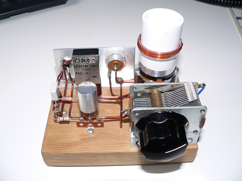
I now have the receiver running with a real Colpitts VFO.  The inductance is provided by an adjustable, shielded coil at around 1.5 uH (it was on the board) in series with a 3 uH toroid (type 6 yellow).  The feedback caps are at 2200 pf with a 1020 cap in series.  The main tuning cap is a small air variable with 73 pf max.  This only lets me tune about 40 kHz of the band, so, in a variation on the old Main Tune -- Bandspread technique, I have a rotary switch that adds capacitance in parallel with the main tuning cap.  I can now tune from 7.141 to 7.300.  The tuning rate is fine and I didn't have to mess with a reduction drive. 

More Barbados receiver blog posts here:
http://soldersmoke.blogspot.com/search?q=barbados

Kind of amazing that DeMaw designed this thing 34 years ago.  A lot of soul in this old machine.   


Thursday, May 12, 2016

The Solder Is Smoking at N6QW!

It is very good to see the solder flowing again in the Newbury Park Laboratories of Pete Juliano, N6QW.  Check out that postage stamp-sized display.

More details on Pete's newest rig can be found on his blog:

http://n6qw.blogspot.com/2016/05/a-new-ssb-transceiver-from-n6qw-with.html


Tuesday, May 10, 2016

Putting Junk Mail to Excellent Use: Tony G4WIF's Proto-boards


Tony's Version of Audio Section of N6QW's LBS Receiver


Tony Fishpool, G4WIF writes:


I’ve been intrigued by Pete’s matrix pad method. Of course, few of us have the machinery to mill them as Pete does, but etching is a possibility. Now some of Pete’s boards clearly have a lot of noodling behind them. His boards are quite big with little areas of pads and space between. The layout for the whole project has clearly been considered in advance.

I wanted a board that I could make modular, take little time to etch and adapt for the circumstances. These “proto-boards” are the result.

The project is Farhan’s “sweeperino” and one board is for the Si570, and the other the AD8307.

The Si570 board is now complete and working:


The PCB method is pure Chuck Adams. His videos on YouTube describe the toner transfer method better than I could.

The only difference for me is that my glossy paper comes free from travel agent brochures.

Just express a passing interest in Viking River Cruises and you will never pay for PCB paper ever again!

There is a free printing only version of the software I use, so if SolderSmoke listeners want to use the proto-board design, I will happily email them the files.


Kind regards
Tony G4WIF
Designer: Douglas Bowman | Dimodifikasi oleh Abdul Munir Original Posting Rounders 3 Column