Podcasting since 2005! Listen to Latest SolderSmoke

Tuesday, October 31, 2023

Building a Crystal Set (Videos)


Andreas DL1AJG in Germany sent the above video to me.  Andreas is the fellow who ran the course in which his university-level students built direct conversion receivers.  

I like the presenter's technique.  But it would have been cooler if he actually used a chunk of Galena or Iron Pyrite, with a cats whisker.  (I still have some of the Iron Pyrite that Mike KL7R gave me many years ago.)  I think that all radio amateurs should (as a rite of passage) actually poke a crystal with a cats whisker in search of a signal. Like here: 


 Thanks Andreas!

Sunday, October 29, 2023

Apollo Core Rope Memory -- CuriousMarc Takes it on (video)


Here is another amazing Apollo video from CuriousMarc (AJ6JV).  Thanks to Bob KD4EBM for alerting me to this. We have recently been discussing the "Apollo rope memory" as I read Sunburst and Luminary by Don Eyles (ex K4ZHF). In this video Marc and his colleague Mike get ahold of some actual Apollo memory modules, develop a device that allows them to read it,  and they discover a design error.  Wow.  

My analog HDR head hurts after watching this.  Even Marc says he was approaching his limits in explaining all this.  

I had not heard of the bug they discovered in the Apollo 11 software just a month before launch, and how they had to climb into the Saturn V to fix it.  Amazing.  

Thanks Marc, thanks Mike and thanks Bob. 

Saturday, October 28, 2023

Mattia Zamana's Amazing Direct Conversion Receiver

Thanks to Ed KC8SBV for sending me this awesome video.  It looks like Mattia built this receiver way back in 1995.  The tuning indicator is very cool, and I had not seen a similar indicator before (could this be a way for us to escape the clutches of the San Jian counters or the Arduinos?)  The Italian ham magazine articles are great, and you can follow the rig description even if you can't read the Italian.  The pictures in in the attached drive are also very good.  

WB9ZKY used Google Translate to get English versions of the articles.  Thanks Chuck! 

https://www.dropbox.com/scl/fi/kil3osilchqlyk8afim2r/part1.pdf?rlkey=9ubgaqb8t4k91d1a10su9mw1p&dl=0

https://www.dropbox.com/scl/fi/t2790qatf5riepyqh5oj1/part2.pdf?rlkey=bhs77gkcchziakh7ngjbpuaz7&dl=0

I have been in touch with Mattia via YouTube:  He reports that he has done other electronic projects, but he considers this to be the most interesting.  He does not have a ham license -- he has a Shortwave Listener license.  His father was a ham:  I3ZQG. 

This is one of the rare cases in which the builder should -- I think -- be issued his ham licence purely on the basis of this build.  

Mattia writes:  

Jul 25, 2023 ITALIA

Mattia Zamana


Monday, October 23, 2023

Bringing a Faulty Herring Aid 5 Receiver Into the Light -- Fixing the AF Amp Schematic Error (video)


I picked up this old homebrew receiver in March 2023 at the Vienna Wireless Society's Winterfest Hamfest.  It is a Herring Aid 5.   I was surprised to see that the builder (who was he?) got the windings on the VFO transformer right.  Later, I learned that he had also substituted MPF-102s for the original Radio Shack FETs called for in the QST article. This allowed him to overcome the PC board layout problem at Q5 (VFO).  With an MPF-102, he was able to get Q1 working by kind of shoe-horning the leads into the proper holes.  FB OM.  Whoever he was, he seemed like a really competent builder.

The Hamfest Herring Aid 5

But then I started wondering:  Did he also overcome the big problem in the audio amplifier?  You see, there is an egregious error in the QST schematic.  Between the collector of Q3 and the base of Q4 (the two AF amplifiers) they have a 10uF capacitor to ground.  That would send most of the audio to ground. This is clearly a mistake.  Not only does it not make any sense, but this cap to ground does not appear in the PC board drawing, nor in the photograph that went with the QST article.  I included this cap in my 2014 built of the Herring Aid 5, but with it, I found the receiver to be exceedingly deaf.  When I clipped that capacitor out of the circuit, my 2014 Herring Aid 5 sprang to life.  Did this hamfest Herring Aid 5 have the error capacitor?  Would it too be brought into the light by clipping one lead?  

Sadly, the erroneous third capacitor was there, and it was wired into the circuit.  The receiver worked,  but just barely.  It was very deaf.  You could not hear 40 meter band noise, and you could barely hear strong CW signals.  Builders may have thought that this was normal with such a simple receiver. 

3 10uF caps. The center one is an error.  I have clipped it out

In the video above you can see what happens when I cut the lead to the mistake capacitor.  Suddenly, you can hear band noise, and CW signals.  The receiver comes to life -- for the very first time!  

This was an error that echoed through the decades.  As far as I know there was never a published errata.  The erroneous capacitor is there in the 1977 ARRL book entitled Understanding Amateur Radio.  In 1998,  NORCAL QRP redid the Herring Aid 5.  Incredibly, THEY INCLUDED THE OFFENDING CAPACITOR in their new and improved schematic.  

NORCAL's 1998 Schematic included C14

I'm fixing up this old receiver a bit.  It was nice to have it playing 40 meter CW yesterday.  Better late than never.  

This morning I was feeling kind of guilty about paying so much attention to a receiver from 1976.  But then I opened the paper and read about the recent find of a DeLorean car.  Heck if a DeLorean from the early 80's is worthy of attention, so is a homebrew receiver from the late 1970s. 

Sunday, October 22, 2023

DIAL SCALE LINEARITY -- Spreading out the Frequencies for the 15-10 BITX Rig

Click on the image for a better view

The 15-10 Rig has been performing very well, pulling in a lot of DX contacts on both bands.  But there is one thing that has bothered me:  The way the transceiver tunes.  It can be a bit difficult getting an SSB station tuned in properly.  At first I thought this was caused by a lack of lubrication on the variable cap that I've been using (out of an old QF-1), but it turned out that this was not the cause.  The problem is something that Pete Juliano has lamented several times:  LC style analog VFOs have a tendency to have the frequencies "bunched up" at one end of the tuning range.  In other words, the tuning range is far from linear.  I was having trouble tuning stations on on the portion of the band where the frequencies were bunched up.  I did some quick measurement and found that on this side of the capacitor's tuning range, one turn of the dial would move the frequency about 100 kHz -- that is far too much.  On the other end of the capacitor moved  only 22 kHz with one turn of the dial (as I recall this is close to the recommended 20 kHz per dial rotation).  Clearly I had a lot of the dreaded bunching up.  This was what was making tuning difficult. 

I had built a pretty standard Colpitts FET VFO.  I had a 6.6uH coil, and a 9-135 pF variable cap in series with a 68 pF fixed cap.  I was pleased that the VFO worked, and I put it in the circuit.  Only later did the bunching up shortcomings become apparent. 

I decided to build another VFO, this time paying attention to DIAL SCALE LINEARITY. 

I turned to the excellent Bandspread Calculator on Bob Weaver's Electronic Bunker web site:  http://electronbunker.ca/eb/BandspreadCalc.html

I plugged in the frequency range that I needed and the values for my variable capacitor.  I calculated Cs which was the combined capacitance of the feedback and coupling capacitors.  Finally, I had to make a decision about the nature of my variable cap:  was it a Midline-Center Cap or was it a Straightline Capacitance cap.  I consulted with Bob and he suggested that it might be somewhere between the two.  I got out some graph paper and measured it -- it looks to me like a Straight Line Capacitance cap, with the capacitance varying linearly with changes in in the rotation of the shaft. 


It looked fairly linear, so I selected "Straightline Capacitance."  Bob's calculator predicted a much better dial scale linearity (see the picture at the top of this blog post). 

I then built the oscillator stage in LTSpice using the values called for by Bob's calculator: 


It worked well in LTSpice: 

So I built it in the real world.  I didn't have the exact values for the padder and trimmer caps, so I use values that were close. 


Using the frequency counter in my Rigol 'scope, I again measured the frequency change for each movement of the shaft. 

Here are the results: You can see that the bunching up has been largely eliminated.  Frequency change for a 20 degree (not %) movement at one end of the capacitor's range is essentially the same as it is on the other end of the range. 

I will continue to play around with the padder and trimmer cap values to get this VFO where I want it.  I may also have to opt for less frequency range in order to get closer to the desired 20 kHz per dial turn value.  I will also have to play around with the additional capacitance that will be switched in to move the VFO down a bit to the range needed for the 10 meter band. 

The bottom line here is that Bob's bandspread calculator is very useful in figuring out how best to avoid the dreaded bunching up of frequencies that can -- sometimes -- come with the use of analog LC VFOs.  The display of Dial Scale Linearity that appears at the end of each calculation is really brilliant, and allow for an instantaneous look at how changes in the various parameters will affect the linearity of tuning.  This is a really wonderful tool for the homebrewer. 

Thanks Bob Weaver! 

Thursday, October 19, 2023

How a Homebrewer Substituted MPF102s for the RS 2035 FETs in the Herring Aid 5 -- Who built this one? Any others out there?

The Hamfest Herring Aid 5

For background on all this, see yesterday's blog post:     https://soldersmoke.blogspot.com/2023/10/a-big-error-discovered-in-1976-qst.html

Rick WD5L noted that it was remarkable how the builder of the Herring Aid 5 that I found early in 2023 at a hamfest had built his receiver using MPF102s at Q1 and Q5.  Here is how this builder  kind of "shoe horned" MPF 102s into the QST Herring Aid 5 boards.  Pinouts for the MPF102 and the RS 2035 and the PC Board Pattern for the Herring Aid 5 appear below. 


Above  is Q5 the VFO.  You can see how he "flipped it around" to get the Drain, Gate, and source in the proper holes. You can also see how he wound the transformer for the VFO.  Looks like there was  a real battle with the soldering iron here. 


Above is Q1 (RF amp).  Again clearly an MPF 102.  But here it would not be sufficient to just flip the transistor around.  So he had to twist it and take the center lead and put it in the far right hole.  Note his markings on the board.  Looks like he made another hole for the MPF102 Gate (but he didn't really have to do this). 

DOES ANYONE KNOW WHO BUILT THIS RECEIVER?  

ARE THERE ANY OTHER HERRING AID 5s OUT THERE?

DSG

DGS! 


Click on the images for better views.

Wednesday, October 18, 2023

A Big Error Discovered in the 1976 QST "Herring Aid 5" Article (After 47 Years)

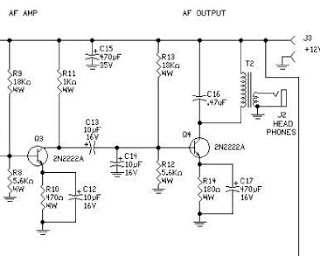
Click on image for a better view.  See arrows for Q1, Q5 and the parts list.

I tried as a teenager to build the Herring Aid 5 direct conversion receiver from the July 1976 issue of QST.  I could not get it to work. Important points: 1) I was attracted to the fact that this receiver used only parts available from local Radio Shack stores (I bought them) and 2) The article provided a PC board pattern (I also bought ferric chloride and etched a board). 

Looking back, I concluded that I had failed to get the VFO to oscillate.  I remember hearing signals when I tuned my HT-37 transmitter (on Cal, on 40) near the receiver.  I was very close, but I never got that Herring Aid 5 VFO to oscillate.

Thirty-eight years later I tried again to build the receiver.  Important points:  This time I used mostly junk box parts and Manhattan-style construction (no etching).  Still I could not get the VFO to work.  ZL2DEX spotted a problem -- I had wound the L6 and L7 coils with the wrong "winding sense."  I corrected this, and BOOM! the VFO sprang to life.  I assumed that I had made a similar "winding sense error" way back in 1976.  This, I thought, explained my failure to get the receiver working.  The QST article had warned that proper phasing of L6 and L7 was necessary.  I figured that I just hadn't fully understood what "proper phasing" meant.  So it was, I thought, all my fault.    

 
Here is the PC board pattern from QST.  Arrows show Q1 (DGS) and Q5 (DSG).  
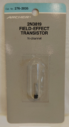
But it is the same kind of FET!  Click on the image for a better view.

But then on October 17, 2023 a comment appeared on the SolderSmoke YouTube channel.  Rick WD5L had also -- back in the late 70's -- tried to build this receiver.  He recently looked closely at the recommended parts list (that we used!) and at the QST PC board pattern (that we also used). AND HE SPOTTED AN IMPORTANT ERROR IN THE QST PC BOARD PATTERN.   

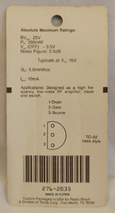
Take a look at the pattern for Q5 above (see arrow).  That is the VFO FET.  A Radio Shack 2035 FET has a DGS pinout (see below).   The Gate is the center pin.  If you put this transistor into the PC board pattern above you would definitely be grounding the Gate.  There is no way the VFO would work under these circumstances.  Note too that the only other RS 2035 FET in the receiver is Q1 (the RF amplifier).  In the PC board pattern above Q1 is marked correctly as DGS.  This confirms the error in the Q5 PC board pattern.  There is no way an RS 2035 transistor can simultaneously have two different pinouts! 

Wow.  So this failure to get the VFO working may not have been my fault after all.  I may have actually gotten the transformer winding correct, but even if I did, there is no way this VFO would have worked using the part called for by QST and the PC board pattern shown above.  As a teenager I just did not know enough to spot the error or the inconsistency.  I kind put blind trust in QST.  I just couldn't get the thing to work.  

Rick searched the QST archives to see if they ever put out an errata on this.  So far, nothing. Worse yet, the scan of the PC board pattern on the QST site is very unclear and may have the pin designations on Q5 scratched out. This would make it more difficult to spot the problem.  (The image above is not from ARRL.  It is from a high quality scan of the original QST article done this week by a fellow Vienna Wireless Society member.)  Please let us know if you find any kind of errata or any acknowledgment of error.  

This is really pretty bad.  This was a project aimed at novices.  Far from encouraging homebrewing, this type of mistake is the kind of thing that would push people away from the soldering iron.  

Ironically, I may have been doomed by opting to use the QST PC board.  If I had used Manhattan-style construction (as I did in my more recent build) I would not have fallen victim to this PC board pattern error.  Also, if I had built this thing stage-by-stage (as we always now recommend) I would have more clearly realized (back in 1976) that the problem was in the VFO stage.  But I was 17 and didn't know.  I put blind faith in the QST article.  It never occurred to me that something in print could be wrong.  This realization came much later. 


There is more to talk about on this ill-fated project. In future posts I will discuss another error, this one in the AF amplifier.  And possible additional errors...  And I'll write about the 1998 resurrection of this project by NORCAL QRP and the New Jersey QRP clubs.  

Thanks to Rick WD5L for spotting the PC board error. 

Monday, October 16, 2023

Does Matching Matter? (Diode Matching for Diode Ring Mixers) -- Nick M0NTV Finds the Answer (Video)


In this video, Nick M0NTV takes on a hot topic in ham radio homebrewing:  The matching of diodes in diode ring mixers.   How should the matching be done and -- more controversially -- is this matching necessary?  

I won't spoil it for you by giving the answer.  Watch Nick's video to find out if it matters.  (But a hint appears below.)

I think it is great that Nick has taken the trouble to look carefully at this issue, and has found info that will be of great use to  homebrewers.   And I really liked Nick's response to the fellow who suggested just going out and buying a commercial diode ring:  Nick replied that he homebrews because he likes to, and because he wants to know how these circuits work.  FB Nick. 

I was also pleased that Nick gave some much warranted recognition to Pete Juliano for his idea regarding the placement of a trim pot on a diode ring.  This idea made it into the Experimental Methods in RF Design book (under Pete's old call: W6JFR).  Page 6.56. 


Sunday, October 15, 2023

Spy Rigs, Para Sets, Bugs, and Enigma Machines -- Dr. Tom Perera W1TP (video)


This is a really amazing presentation by Tom Perera W1TP to the Fairlawn (NJ) Amateur Radio Club. 

There is so much great info in this presentation.  Some of the highlights for me: 

-- The U.S. Civil War telegraphic (wired) spy set was just mind blowing.  I had never heard of this.  

-- The way the Nazis transmitted a signal 1 kc off the BBC frequency, so that Germans who tuned their Nazi-issued receivers to the BBC could be detected by neighbors (from the resulting 1 kc tone!) and turned in to the Gestapo.  

-- "Things don't land gently when dropped by parachute." Indeed.  This was a reminder of the courage of the young women who parachuted into Nazi-held territory during WWII.  Like Paulette.  It was great to see her with her Paratrooper wings on.  AIRBORNE!  And the picture of the operator with the bicycle generator was of Virginia Hall.  See: https://www.npr.org/2019/04/18/711356336/a-woman-of-no-importance-finally-gets-her-due  That portrait hangs in the hallway of the National War College. 

-- How they put the schematic of the PRC-5 right into the box.  Great idea.  But it had a terrible receiver.  One of the schematics showed a 455 kc IF and a BFO.  So they sent in superhets, not just regens. 

N2CQR operating the Para Set of G3ROO around 2009

This video makes me want to build a Para Set. 

Thanks a lot to Tom W1TP and the Fairlawn ARC. 

Saturday, October 14, 2023

Paul VK3HN's Video on Scratch-Building and SOTA


It was great to get a comment from Paul VK3HN -- this led to a re-establishment of contact.  Apparently Google knows who I have been e-mailing, so this great video appeared on my YouTube screen.  Thanks Google! 

-- Great to hear Paul's shout out to Pete Juliano N6QW, and Pete's concept of noodling. 

-- Paul's emphasis on testing each stage independently is really important. 

-- Wow, ferric chloride!  It is great to see someone doing this (instead of just sending Gerber files to China). 

-- Books.  This reminds me that I have to get Drew Diamond's books. 

-- Paul's comment on the usefulness of a general coverage receiver.  Right on target Paul.  

-- On the test gear, we can now add the TinySA Ultra.  And you don't have to win the Lotto! 

-- Finally, Paul is absolutely right on the need to constantly update and publish changes to schematics. I am guilty of not doing this. (I hang my head in shame.)   This became a problem in our simple High-School receiver project -- I would make changes to circuits and fail to communicate these changes to Dean KK4DAS.  Paul's method would have solved this problem.  

-- Thanks Paul! 

Wednesday, October 11, 2023

Sunburst and Luminary: Apollo "Rope" Memory, and other items of interest


Wow.  That is the method that they stored computer memory for the moon missions.  When they were satisfied with a program they would say it was time to "put it on the rope."  

Here's an article on the women who built the rope memory (and the integrated circuits used in Apollo). This reminded me of the women's collective in Hyderabad that "wove" the ferrite core transformers for Farhan's BITX rigs: 

https://www.sciencenews.org/article/core-memory-weavers-navajo-apollo-raytheon-computer-nasa#:~:text=Core%20memory%20used%20metal%20wires,to%20create%20a%20particular%20pattern.

Here is a Wikipedia article on core rope ROM memory with some great illustrations: 

https://en.wikipedia.org/wiki/Core_rope_memory

The Rope

Other stuff of interest that I have spotted so far in the book Sunburst and Luminary -- An Apollo Memoir by Don Eyles:  

-- Not long before the fatal Apollo 1 fire, an MIT colleague of Don Eyles had a drink with Astronaut Gus Grissom.  Grissom unloaded about the poor state of the spacecraft, saying that, "What we have here is a Heathkit."  Grissom died in the fire. 

-- Eyles mentions the use of 6L6 tubes in analog audio amplifiers. 

-- MIT's Doc Draper used a Minox camera.  

-- When the Apollo 11 astronauts came back and were living for two weeks in an isolation chamber, NASA had bulldozers on standby to bury the whole thing ("astronauts, staff and all") in case some dangerous moon bug was detected.  (Is that true?) 

-- At one point soon before an important missile test, engineers realized that they needed an isolation transformer.  They did not have enough time to order one.  So they took an isolation transformer out of one of their soldering stations and used it in the missile.  It worked. Sometimes you just use what you have on hand. 

Designer: Douglas Bowman | Dimodifikasi oleh Abdul Munir Original Posting Rounders 3 Column