Podcasting since 2005! Listen to Latest SolderSmoke

Showing posts with label 75 meters. Show all posts

Monday, February 14, 2022

6EA8s in the Mate for the Mighty Midget, and WA9WFA Re-Builds a Heath HW-12


I reported to Scott and Grayson that I had finally gotten around to changing the three aging 6U8 tubes in my Mate for the Mighty Midget receiver.  I replaced them with three more youthful 6EA8s.  This switch really seemed to perk up the old receiver.   I'm listening to 75 meters on it right now. 

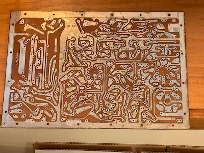
Speaking of 75 meters, Scott sent me this picture of his latest effort:  re-building a Heathkit HW-12.  FB.  This is a way of experiencing (or re-experiencing) the construction of a Heathkit.  I did something similar, but much less complicated)  with a Heathkit VF-1.  Scott did a wonderful job taking this old rig apart.  That PC board looks great (see photo below). 

Scott's e-mail:  

Hi Bill and Grayson, I’m glad to hear of your good results with the 6EA8’s in your MMMrx! I had similar results when I finally got rid of the 6U8’s with their iffy performance and went with the 6EA8’s.  I did put a set of 6GH8A’s and tried it out, it worked, but I don’t have any data on performance improvements.  After completing the outboard power supply and audio amplifier, I’ve taken a break from my MMMRx and it’s sitting there on the bench. I’ll get back to it in a while.  


In the meantime I’ve started a new project where I’m re-kitting a Heathkit HW-12 eighty meter transceiver.  I have completed the disassembly process including the pcb.  I bought a Hakko vacuum desoldering iron for taking all (ALL) parts off of the pcb, and it’s bare now.   I’m planning to start rebuilding this coming week.  73 Scott WA9WFA  


Saturday, August 7, 2021

Mythbuster Video #13 -- RF Power Amplifier, and Relay Switching Plan


In this episode we enter into the most fraught part of the construction project: the production of RF power. This is where amplifiers stubbornly turn into oscillators, and where components release magic smoke, or at least burn the fingers of hopeful builders.

I kind of ran out of room when I built the low-pass filters. But, thinking ahead, I wanted to have them on a separate board. And it is good that they ended up in the far corner of the rig.

Just going from one band to two bands adds to the complexity of the rig. I had to add two relays, one to switch the low pass filters, the other to switch the bandpass filters. I ended up with 5 DPDT relays in this transceiver. It was very helpful to have a plan and a diagram for the relays and all the switching.

It looks like each of the three RF amplifier stages provides about 15 db of gain -- about what I need to get to the 5 watt level.

Thursday, June 17, 2021

The Stubborn Myth about USB and LSB

It  has been repeated so often and for so long that many of us have come to believe it.  I myself believed it for a while.   Like many myths, it has a ring of truth to it.  And it is a simple, convenient explanation for a complex question: 

Why do ham single sideband operators use LSB below 10 MHz, but USB above 10 MHz? 

Here is the standard (but WRONG) answer: 

In the early days of SSB, hams discovered that with a 9 MHz SSB generator and a VFO running around 5.2 MHz, they could easily reach both 75 meters and 20 meters (True). And because of sideband inversion, a 9 MHz LSB signal would emerge from the mixer as an LSB signal (True), while the 20 meter signal would emerge -- because of sideband inversion -- as a USB signal (FALSE!)  That sideband inversion for the 20 meter signal explains, they claim,  the LSB/USB convention we use to this day. 

Why this explanation is wrong: 

There is a very simple rule to determine if sideband inversion is taking place:  If you are subtracting the signal with the modulation FROM the signal without the modulation (the LO or VFO) you will have sideband inversion.  If not, you will NOT have sideband inversion.

So, you just have to ask yourself:   For either 20 or 75 are we SUBTRACTNG the Modulated signal (9 MHz) from the unmodulated signal (5.2 MHz)? 

For 75 meters we have:   9 MHz - 5.2 MHz =  3.8 MHz    NO.  We are not subtracting the modulated signal from the unmodulated signal.  There will NOT be sideband inversion. 

For 20 meters we have 9 MHz + 5.2 MHz = 14.2 MHz.     NO.  No subtraction here.  No sideband inversion.   

So it is just arithmetically impossible for there to be the kind of happy, easy, and convenient  USB/LSB situation described so persistently by the myth. 

---------------------------------

We discussed this several times on the podcast and in the blog: 

https://soldersmoke.blogspot.com/2015/05/sideband-inversion.html

https://soldersmoke.blogspot.com/2012/05/usblsb-urban-legend-debunked.html 

This myth shows up all over the place: 

We see the myth here: 

http://n4trb.com/AmateurRadio/Why%20The%20Sideband%20Convention%20-%20formatted.pdf

Here the web site owner warns that this is "highly controversial."  Really?  Arithmetic? 

http://9m2ar.com/lsb7.htm

The myth is very old.   Here is a clip from a 1966 issue of "73" magazine: 

https://worldradiohistory.com/Archive-DX/73-magazine/73-magazine-1966/73-magazine-01-january-1966.pdf

Finally, to my disappointment, I found the myth being circulated by the ARRL, in the 2002 ARRL Handbook page 12.3: 


The fact that the Handbook attributed this to a desire to "reduce circuit complexity" by not including a sideband switch should have set off alarms.  We are talking about hams who built their own SSB rigs, usually phasing rigs.  A sideband switch would not have added significant circuit complexity. I think they could have handled it. 

It is interesting that earlier ARRL Handbooks do not repeat this myth.  I found no sign of it in Handbooks from 1947, 1959, 1963, 1973, and 1980.  And I found no sign of it in several editions of that great ARRL book "Single Sideband for the Radio Amateur." 

For my next homebrew rig, I will build a rig that DOES do what the myth promises.  I will have the SSB generator running on 5.2 MHz USB.  The VFO (out of an old FT-101) will be running around 9 MHz.  So for 75 meters we WILL be subtracting the signal with the modulation from the signal without the modulation:   9 MHz - 5.2 MHz = 3.8 MHz.   There will be inversion.  This 75 meter signal will be LSB.   For 20 we will just add the 5.2 MHz USB signal to the 9 MHz  VFO.  There will be no inversion.  We will have a USB signal on 20.   I'm thinking of calling this new rig "The Legend." Or perhaps, "The Mythbuster." 

Tuesday, July 28, 2020

A 75 Meter AM Quarantine Converter for the Q-31 Receiver (video)


A while back Fred KC5RT sent me a nice collection of parts, including some 6 MHz crystals.  I had been thinking of making a converter to put ahead of my Q-31 receiver.  When Fred's 6 MHz rocks arrived, I knew that The Radio Gods Had Spoken (TRGHS).  

I found some NE602 chips in the junk box.   I used an Altoid-sized box for the case.  The toroids are from W8DIZ.  I use trimmer caps from KC5RT to resonate the input and output circuits.  

Hooray!  Now I can listen to 75 Meter AM on the Q-31.  I may have to build a transmitter to go with this contraption.  

Thanks again Fred. 

Friday, May 15, 2020

Nick M0NTV's Quarantine Rig: The Bread Bin 80


Hi Bill,

Hope you are keeping well and staying safe.

Just thought I’d let you know about a homebrew project I’ve just completed. I call it the Bread Bin 80 - you’ll see why!

It is a single band (80m) SSB transceiver that puts out 25-30W of clean RF. It uses the familiar pairing of Arduino Uno + Si5351 (with 16x2 LCD screen and rotary encoder for tuning). Other than this though it is largely an analogue beast - which I thought you might like!

I made my own double balanced mixers which work really well. But the Si5351 can’t generate the 7 dBm of local oscillator signal to drive them so I then had to build a simple one transistor RF amp for each clock of the Si5351. I even went above and beyond the call of duty and home-brewed my own IF crystal ladder filter (although this was actually a kit).

The rig has a three stage IF cascade amplifier with 2 back to back JFETs in each stage + AGC and analogue S meter. There is something very satisfying about seeing the needle bob about as you are listening. I also put in a switchable analogue audio filter in front of the audio pre-amp which cuts out some of the higher frequency noise on the band.

Overall I’m really pleased with the rig. I’ve been working stations all over the UK and into continental Europe and getting some great reports. Except the one guy (who shall remain nameless) who wasn’t the least impressed that I was working him on a homebrew rig: he was only keen to point out that my antenna must be far too low to give me such an attenuated signal!!! I guess you can’t please everyone.

Anyway, I’ve done a bit of a write up and included some photos (outside and in) on my QRZ page if you are interested:


Thanks for sharing your home brewing story about your short wave receiver on YouTube. I’ve enjoyed following that and seeing it progress. Those little ‘Altoid’ tins are great aren’t they.

Thanks again for all your encouragement through the Soldersmoke podcast. I really enjoy it.

Stay In The Shack!

73 from across the Pond.

Nick

M0NTV
Nick Wood


Monday, July 29, 2019

Walter KA4KXX Operates his FB Al-Fresco HB Scratch-Built BITX 75 (Video)


Dear Bill N2CQR:

For your amusement, the attached video (from 2:20 - 3:40) shows
me operating portable at a tailgate event using my second
scratch-built  BITX, with this one running 45W on 75M. 
Features include analog VFO, a 16-pin LM380 with all ground
pins heat-sinked for powerful audio, and 3-transistor uBITX-type
low-level RF amps.  The 8-crystal filter is also like the uBITX design
but at an 11 MHz IF.  The microphone amp is a 741 Op Amp which I
believe has better gain, gain adjustability, and frequency response than 
any of the transistor designs. The transmit adjustable driver amp is adapted from the FET 
circuit used in the Wee Willy.  The Transmit LPF is hard-wired to the antenna connector 
for simplification and to minimize RF losses, so in receive mode the single relay in the rig 
connects the receive section in parallel, which causes some signal loss, but not much. 
Finally, and most notably, I believe that my RF Power Amp is the only one in the world to use 
model airplane engine mufflers as heat sink cores...

72,
Walter
KA4KXX
Orlando, FL     

Thursday, August 23, 2018

W2NBC's AM Boatanchor Video


W2NBC was booming in on 3885 kHz AM this evening.  I took a look at his QRZ.com page and found this video.  Very nice.  

I've been on 75 meter AM with the K2ZA DX-100 and my new 135 foot doublet antenna.  

Saturday, May 12, 2018

NN2K's Beautiful Pine-Board Al-Fresco Thermatron AM Transmitter


On Saturday mornings (around dawn) I often listen to the Old Military Radio Net on 3885 kHz.  I find it inspirational.  This morning the inspiration was provided by Rick NN2K.  His signal from Binghamton New York was makeing the trip to Northern Virginia.  When I heard him mention that he was using a "Pine Board Transmitter" I felt the urge to look for a picture.  QRZ.com provided the photo.  

Rich says he built this rig in January 2018 based on a QST article by Bob Heil.   FB Rich! 
And thanks to Ted W3PWW for running the Old Military Radio Net for so many years. 


Sunday, May 27, 2012

Homebrew QRP Fun on 75 Phone

OK, I take back all of the bad things I said about the 75 meter phone band. I recently finished work on my Kick Panel 75 meter DSB rig.  Last week I took portions of the multiband antenna that Solder-Lexicographer Steve Silverman sent me and turned it into a 75 meter dipole.  It is now suspended in the trees above my house.  With some trepidation I ventured out into the 75 meter ether.  And, to my surprise I found friendly hams willing to give my 3 watt DSB signal a chance.   The first contact was with K2WS.  I had called Billy into the shack, thinking that I was just going to show him the beauty of a Direct Conversion receiver.  To my astonishment I found K2WS calling CQ!  On 75!  Who knew?   I gave him a call and -- BINGO -- we had a wonderful QSO.  Alan is at the other end of the tech spectrum -- he was running a Flex Radio.  With that rig's panoramic display he was able to SEE that I was running DSB.  Very cool.  Billy was duly impressed. 


Yesterday morning I ran into a very congenial bunch of guys from the Gallups Island Radio Club.  They welcomed me into the group and allowed me to join in the roundtable.  Thanks guys! 


Then came the icing on the cake.  This morning I heard a familiar voice calling together the Mid Atlantic chapter of the Quarter Century Wireless Association.  Could it be?  Yes indeed, it as an old friend, Ray, a guy who had brought me into the QCWA group during our previous stint in Northern Virginia. I checked into the net and had a great time. 

Above you can see the latest version of this long-evolving rig.  It has a built-in speaker.   Below you can see it with the top off. 

Three cheers for 75! 

  
Our book: "SolderSmoke -- Global Adventures in Wireless Electronics" http://soldersmoke.com/book.htm Our coffee mugs, T-Shirts, bumper stickers: http://www.cafepress.com/SolderSmoke Our Book Store: http://astore.amazon.com/contracross-20
Designer: Douglas Bowman | Dimodifikasi oleh Abdul Munir Original Posting Rounders 3 Column