Podcasting since 2005! Listen to Latest SolderSmoke

Showing posts with label Herring Aid 5. Show all posts

Tuesday, December 5, 2023

The Beginning of MY Radio Life...

 
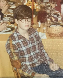
Unlike Pete (see below), I don't have any cool pictures of me in front of an early station.   But in the picture above,  there I am, at the Thanksgiving table in 1973 age 15.  I was on the air by this date, on CW as WN2QHL.  Armed with a Lafayette HA-600A and a DX-40, I was tearing up the ham bands, especially 40 meters.  Look at the tension in my face, the grip of my fist... I just wanted to finish that turkey and get on the air!  But no, I had to have Thanksgiving dinner. 

I recently realised that I have been a ham for more than 50 years. Is there an HCWA?    

This and the recent movie from India led me to think about the timeline of my early radio days: 

-- Christmas 1972.  Santa brings me a Lafayette HA-600A general coverage receiver.  With jeweled movements.  Age:  14

-- April 27, 1973.  Novice Ticket becomes effective.  WN2QHL.  Age 14. 

-- July 19, 1973.  First contact (with Elmer WN2NEC).  Age 14.

-- February 1 and 2 1973.  A grumpy old-timer calls -- during the Novice Roundup! -- to tell me that I'm putting harmonics onto the 20 meter band.  I get scared and go off the air.  Geez!  I probably just needed to retune the tank circuit.  Age 15. 

-- February 23, 1974.  I go back on the air with a DX-100.  Age 15. 

-- March 5, 1974.  I take the General Class exam at the FCC office in New York City. I pass. Age 15. 

-- April 11, 1974.  I buy the Drake 2-B from WN2NEC. This revolutionizes my radio life.  Fifteen meter contacts become possible.   Age 15. 

-- April 13, 1974.  I work ZL2ACP on 15 meter CW.  I wake up my parents to tell them.  Age 15. 

-- April 21, 1974.  END OF NOVICE OPERATION.  Apparently we were still working under a one year limitation on Novice operation.  Could the expiration date have been marked on the license? 

At this point the FCC screwed up and sent me a Technician License instead of a General Class License.  My father got on the phone to Gettysburg and straightened this out.  Thanks Dad.  So I was only a Technician for a few weeks. 

-- April 9, 1974.  General Class License effective.  I become WB2QHL,  a man of substance.  Age 15. 

-- May-June 1974.  I acquire a Heathkit HW-32A 20 meter SSB transceiver from the Crystal Radio Club.  But I have to build the power supply from an old TV.  Somehow, I survive. Age 15. 

-- June 11, 1974.  First contact with the HW-32A.  Age 15.   

-- November 9, 1974.  Last contact with the HW-32A . Age 16. 

-- March 15, 1975.  First contact with my Hallicrafters HT-37. Age 16. 
Above is my only photo of my teenage ham radio station.  I can date it via the QSL card above the map. I still have that card.  I worked W7RUK on March 25, 1975.  That contact was on 20 SSB, but when this picture was taken I was on CW (the key is plugged in, not the microphone).   

-- June 1976   I graduate from High School.  Age 17.  

-- I was active and on the air through the summer of 1976. 

-- July 1976 -- QST article on the Herring Aid 5 receiver.  I try to build it and fail.  Age 17. 

-- October 1976 -- I depart for Army Basic Training. 

There is someone else who needs honorable mention here:  My sister Trish.  Here she is, next to me at the Thanksgiving table in 1973.  Trish helped me keep my ham radio log book.  Thanks Trish! 

Pete Juliano, Field Day, 1959.  With a DX-100B and (gasp!) a QF-1. 

Friday, November 10, 2023

SolderSmoke Podcast #249 -- Travel, Pete's 6BA6 rig, Books!, VFOs, SDR, Computers, Spectrum Analysers, Transistor Man! MAILBAG

New VFO for 15-10 Transceiver
Schematic below

SolderSmoke Podcast #249 is available:  http://soldersmoke.com/soldersmoke249.mp3

There is also a video version of this podcast: https://youtu.be/5xyaYivtOhw

Travelogue:  

HAPPY VETERANS' DAY TO PETE AND GRAYSON AND TO ALL THE OTHER VETERANS WHO ARE LISTENING. 

Trip out to San Francisco. Sticker placed on the corner of Haight and Ashbury:  See picture below.  Note other sticker.  Really Groovy! 

Bill's DXCC-100.  DONE.   

Tribal Wisdom:  W1REX on HRWB https://soldersmoke.blogspot.com/2023/11/listen-to-rex-w1rex-lots-of-tribal.html

Pete's Bench:

Pete's 6BA6 rig

Pete's 6BA6 Rig

Pete Re-invents the Shirt-pocket SSB Rig

Pete's remake of the ShirtSleeve Transceiver

Pete Builds Two Computers 

Pete Adds a Second Band to his Homebrew SDR 
 

SHAMELESS COMMERCE DIVISION:  

BEZOS BUCKS ARE BACK!  PLEASE  BUY THERE! >>>>>>>>>>>>>>>>>>>>>>>

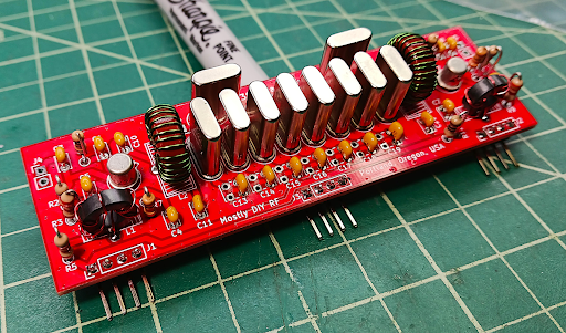
Mostly DIY RF:  Work proceeds in the Oregon Silicon Forest on P3ST kit development. Todd is confident the P3ST will be released on December 18th.Many other kits available now:  https://mostlydiyrf.com/ 

Sign up for the newsletter:  https://mostlydiyrf.com/subscribe/ 


Bill's Bench: 

Rebuild of the 15-10 VFO (for improved Dial Spread) (with yet another QF-1 capacitor) https://soldersmoke.blogspot.com/2023/10/dial-scale-linearity-spreading-out.html

Why Building for 10 meters is harder: https://soldersmoke.blogspot.com/2023/09/why-building-for-10-meters-is-harder.html

Copper Tape shielding of 15-10 rig. 

Crushing Spurs with Better Bandpass Filters (see blog post) https://soldersmoke.blogspot.com/2023/09/crushing-17-and-12-meter-spurs-with.html

Another 15-10 rig in the works... for SSSS.   Boards are accumulating... 

More problems discovered with the Herring Aid 5 Receiver . Lots of SS blog posts  Comment from Rick WD5L.  ) https://soldersmoke.blogspot.com/2023/10/a-big-error-discovered-in-1976-qst.html   Did you try to build one?  Did you succeed or did you fail?  Please let us know. 

The Basil Mahon books (blog posts) https://soldersmoke.blogspot.com/2023/11/basil-mahon-is-author-for-us-he.html

The Sunburst and Luminary book of Don Eyles (blog posts) 

The Art of Electronics by Horowitz and Hill (blog posts) 

Spectrum Analysers:  Tiny SA Ultra https://soldersmoke.blogspot.com/2023/09/the-tinysa-ultra-spectrum-analyser-video.html  and Polarad 632C-1; George WB5OYP gave me one of these spectrum analysers  (I NEED a manual! Does anyone have a manual or a schematic? )  : 

Polarad 632C-1

Stabilizing the EB63A (with Pete recommended LP filters from e-Bay. 


MAILBAG:

TRANSISTOR MAN T-SHIRTS!  Thanks to Roy WN3F! 

Todd VE7BPO on AF amplifiers.  Thanks Todd.  

Wes W7ZOI -- Always a privilege to exchange e-mail with Wes. 

E-mail from Jay Rusgrove W1VD. About the Herring Aid 5. 

E-mail from Eamon Skelton EI9GQ!  Amazing! 

HB2HB with Denny VU2DGR https://soldersmoke.blogspot.com/2023/09/hb2hb-contact-with-denny-vu2dgr.html

Nick M0NTV on diode matching for ring mixers: https://soldersmoke.blogspot.com/2023/10/does-matching-matter-diode-matching-for.html

Paul Taylor VK3HN on the new Elecraft CW rig. 

Dean KK4DAS fixed the noise in his Hallicrafters SW receiver.  A long battle, finally won. 

Dean also in contact with G3UUR. 

Ramakrishnan VU2JXN helping me set up a backup of blog on WordPress.  

Mark KA9OOI noticed that SS podcast archive appears gone.  In fact just temporarily relocated to http://soldersmoke.com/podcastarchive.html

(SS PODCAST Archive temporarily relocated to http://soldersmoke.com/podcastarchive.html

Andreas DL1AJG - Crystal radio video. https://soldersmoke.blogspot.com/2023/10/building-crystal-set-videos.html

George N2APB on the Herring Aid 5

Grayson KJ7UM experimenting with Varactors and Thermatrons! 

Thomas K4SWL on Mattia's DC receiver. https://soldersmoke.blogspot.com/2023/10/mattia-zamanas-amazing-direct.html

Bob Weaver of Dial Bandspread Linearity  fame.  Electron Bunker

Mike Bryce WB8VGE QRP Hall of famer -- he too couldn't get the Herring Aid 5 working. 

Kirk NT0Z wrote about the Wayback machine.  But this former ARRL staffer he also tried and failed to get the Herring Aid 5 going.  Way back when... https://soldersmoke.blogspot.com/2015/03/kirks-herring-aid-tuna-tin-and-regen.html


New 15-10 VFO with schematic

Dial Bandspread (Before)

At corner of Haight and Ashbury

Monday, October 23, 2023

Bringing a Faulty Herring Aid 5 Receiver Into the Light -- Fixing the AF Amp Schematic Error (video)


I picked up this old homebrew receiver in March 2023 at the Vienna Wireless Society's Winterfest Hamfest.  It is a Herring Aid 5.   I was surprised to see that the builder (who was he?) got the windings on the VFO transformer right.  Later, I learned that he had also substituted MPF-102s for the original Radio Shack FETs called for in the QST article. This allowed him to overcome the PC board layout problem at Q5 (VFO).  With an MPF-102, he was able to get Q1 working by kind of shoe-horning the leads into the proper holes.  FB OM.  Whoever he was, he seemed like a really competent builder.

The Hamfest Herring Aid 5

But then I started wondering:  Did he also overcome the big problem in the audio amplifier?  You see, there is an egregious error in the QST schematic.  Between the collector of Q3 and the base of Q4 (the two AF amplifiers) they have a 10uF capacitor to ground.  That would send most of the audio to ground. This is clearly a mistake.  Not only does it not make any sense, but this cap to ground does not appear in the PC board drawing, nor in the photograph that went with the QST article.  I included this cap in my 2014 built of the Herring Aid 5, but with it, I found the receiver to be exceedingly deaf.  When I clipped that capacitor out of the circuit, my 2014 Herring Aid 5 sprang to life.  Did this hamfest Herring Aid 5 have the error capacitor?  Would it too be brought into the light by clipping one lead?  

Sadly, the erroneous third capacitor was there, and it was wired into the circuit.  The receiver worked,  but just barely.  It was very deaf.  You could not hear 40 meter band noise, and you could barely hear strong CW signals.  Builders may have thought that this was normal with such a simple receiver. 

3 10uF caps. The center one is an error.  I have clipped it out

In the video above you can see what happens when I cut the lead to the mistake capacitor.  Suddenly, you can hear band noise, and CW signals.  The receiver comes to life -- for the very first time!  

This was an error that echoed through the decades.  As far as I know there was never a published errata.  The erroneous capacitor is there in the 1977 ARRL book entitled Understanding Amateur Radio.  In 1998,  NORCAL QRP redid the Herring Aid 5.  Incredibly, THEY INCLUDED THE OFFENDING CAPACITOR in their new and improved schematic.  

NORCAL's 1998 Schematic included C14

I'm fixing up this old receiver a bit.  It was nice to have it playing 40 meter CW yesterday.  Better late than never.  

This morning I was feeling kind of guilty about paying so much attention to a receiver from 1976.  But then I opened the paper and read about the recent find of a DeLorean car.  Heck if a DeLorean from the early 80's is worthy of attention, so is a homebrew receiver from the late 1970s. 

Thursday, October 19, 2023

How a Homebrewer Substituted MPF102s for the RS 2035 FETs in the Herring Aid 5 -- Who built this one? Any others out there?

The Hamfest Herring Aid 5

For background on all this, see yesterday's blog post:     https://soldersmoke.blogspot.com/2023/10/a-big-error-discovered-in-1976-qst.html

Rick WD5L noted that it was remarkable how the builder of the Herring Aid 5 that I found early in 2023 at a hamfest had built his receiver using MPF102s at Q1 and Q5.  Here is how this builder  kind of "shoe horned" MPF 102s into the QST Herring Aid 5 boards.  Pinouts for the MPF102 and the RS 2035 and the PC Board Pattern for the Herring Aid 5 appear below. 


Above  is Q5 the VFO.  You can see how he "flipped it around" to get the Drain, Gate, and source in the proper holes. You can also see how he wound the transformer for the VFO.  Looks like there was  a real battle with the soldering iron here. 


Above is Q1 (RF amp).  Again clearly an MPF 102.  But here it would not be sufficient to just flip the transistor around.  So he had to twist it and take the center lead and put it in the far right hole.  Note his markings on the board.  Looks like he made another hole for the MPF102 Gate (but he didn't really have to do this). 

DOES ANYONE KNOW WHO BUILT THIS RECEIVER?  

ARE THERE ANY OTHER HERRING AID 5s OUT THERE?

DSG

DGS! 


Click on the images for better views.

Wednesday, October 18, 2023

A Big Error Discovered in the 1976 QST "Herring Aid 5" Article (After 47 Years)

Click on image for a better view.  See arrows for Q1, Q5 and the parts list.

I tried as a teenager to build the Herring Aid 5 direct conversion receiver from the July 1976 issue of QST.  I could not get it to work. Important points: 1) I was attracted to the fact that this receiver used only parts available from local Radio Shack stores (I bought them) and 2) The article provided a PC board pattern (I also bought ferric chloride and etched a board). 

Looking back, I concluded that I had failed to get the VFO to oscillate.  I remember hearing signals when I tuned my HT-37 transmitter (on Cal, on 40) near the receiver.  I was very close, but I never got that Herring Aid 5 VFO to oscillate.

Thirty-eight years later I tried again to build the receiver.  Important points:  This time I used mostly junk box parts and Manhattan-style construction (no etching).  Still I could not get the VFO to work.  ZL2DEX spotted a problem -- I had wound the L6 and L7 coils with the wrong "winding sense."  I corrected this, and BOOM! the VFO sprang to life.  I assumed that I had made a similar "winding sense error" way back in 1976.  This, I thought, explained my failure to get the receiver working.  The QST article had warned that proper phasing of L6 and L7 was necessary.  I figured that I just hadn't fully understood what "proper phasing" meant.  So it was, I thought, all my fault.    

 
Here is the PC board pattern from QST.  Arrows show Q1 (DGS) and Q5 (DSG).  
But it is the same kind of FET!  Click on the image for a better view.

But then on October 17, 2023 a comment appeared on the SolderSmoke YouTube channel.  Rick WD5L had also -- back in the late 70's -- tried to build this receiver.  He recently looked closely at the recommended parts list (that we used!) and at the QST PC board pattern (that we also used). AND HE SPOTTED AN IMPORTANT ERROR IN THE QST PC BOARD PATTERN.   

Take a look at the pattern for Q5 above (see arrow).  That is the VFO FET.  A Radio Shack 2035 FET has a DGS pinout (see below).   The Gate is the center pin.  If you put this transistor into the PC board pattern above you would definitely be grounding the Gate.  There is no way the VFO would work under these circumstances.  Note too that the only other RS 2035 FET in the receiver is Q1 (the RF amplifier).  In the PC board pattern above Q1 is marked correctly as DGS.  This confirms the error in the Q5 PC board pattern.  There is no way an RS 2035 transistor can simultaneously have two different pinouts! 

Wow.  So this failure to get the VFO working may not have been my fault after all.  I may have actually gotten the transformer winding correct, but even if I did, there is no way this VFO would have worked using the part called for by QST and the PC board pattern shown above.  As a teenager I just did not know enough to spot the error or the inconsistency.  I kind put blind trust in QST.  I just couldn't get the thing to work.  

Rick searched the QST archives to see if they ever put out an errata on this.  So far, nothing. Worse yet, the scan of the PC board pattern on the QST site is very unclear and may have the pin designations on Q5 scratched out. This would make it more difficult to spot the problem.  (The image above is not from ARRL.  It is from a high quality scan of the original QST article done this week by a fellow Vienna Wireless Society member.)  Please let us know if you find any kind of errata or any acknowledgment of error.  

This is really pretty bad.  This was a project aimed at novices.  Far from encouraging homebrewing, this type of mistake is the kind of thing that would push people away from the soldering iron.  

Ironically, I may have been doomed by opting to use the QST PC board.  If I had used Manhattan-style construction (as I did in my more recent build) I would not have fallen victim to this PC board pattern error.  Also, if I had built this thing stage-by-stage (as we always now recommend) I would have more clearly realized (back in 1976) that the problem was in the VFO stage.  But I was 17 and didn't know.  I put blind faith in the QST article.  It never occurred to me that something in print could be wrong.  This realization came much later. 


There is more to talk about on this ill-fated project. In future posts I will discuss another error, this one in the AF amplifier.  And possible additional errors...  And I'll write about the 1998 resurrection of this project by NORCAL QRP and the New Jersey QRP clubs.  

Thanks to Rick WD5L for spotting the PC board error. 

Friday, February 11, 2022

Bill Talking about Homebrew Radio with L’Anse Creuse Amateur Radio Club (Michigan) -- February 2, 2022 (Video)


This was a very nice meeting.  We just talked homebrewing and why it is such an important part of ham radio.  Video above

Topics included:

-- Jean Shepherd
-- Being "Electrically Inclined" 
-- The Herring Aid 5
-- Radio Clubs around the world
-- The Shame Shelf
-- Making mistakes, releasing smoke
-- Errors in ham radio magazines and schematics
-- The importance of understanding the circuit
-- The Michigan Mighty Mite
-- Building a power supply for the HW-32A
-- The origins of the SolderSmoke podcast
-- Knack stories, the IBEW and what we all have in common
-- The importance of books

Thanks to The L'Anse Creuse ARC for the invitation. 

Sunday, February 6, 2022

FLASHBACK: The Herring Aid 5 Direct Conversion Receiver and Frank Jones (Video)


The Radio Gods seem to be pushing me towards Direct Conversion receivers.  This week I was speaking via Zoom with the very FB L'Anse Creuse Amateur Radio Club in Michigan.  My Herring Aid 5 tale of woe came up (see video above).   Then Dean KK4DAS was sharing video of the amazing fidelity of the Pete Juliano Direct Conversion Receiver.  Then I started thinking about Frank Jones W6AJF, and the story (fictional) of his build of the Herring Aid 5 by Michael Hopkins AB5L

----------------------

I gave Frank a board for the Herring Aid Five redux from the April 1998 QRP Quarterly and challenged him to build one up. It took maybe two hours and that includes his own touches which included refusing to buy any parts.

For the transformers, he calculated the turns ratios from the impedances and tested a bunch of TV set pulls 'till he found something close. But he made the output 1:1 because his Brandes phones are close to 1000K Ohms as it is. 

He was willing to use toroids, but not to buy one, so I gave him an Amidon circular and he calculated the values of the 18 specified units. Then he wound them on unidentified cores from my junk box after learning the permeability of each with his homebrew dip meter. 

A store bought Zener was out of the question so he mixed and matched regular diodes with transistors hooked up as diodes until he got close enough to 10 volts. The mosfets came out of a TV tuner and Frank will use any plastic bipolar that says "C" or "D" on it for a 2N2222. 

Of course it worked the first time. He rigged up a patch to a pair of Class A push-pull 6L6s so Christie could hear it and she said it was "Also cute but bigger than the other one." 

Now a real QRPer would cry at that, but not Frank who sees no advantage in miniaturization at all. In fact, he mounted the whole thing in an old case from a Collins 6 and 2M transceiving attachment he junked out for the parts and no two knobs matched as Frank thinks matching knobs slow you down in a pileup. He wanted to take it back to his own shack and try it out with his breadboard MOPA and pair of 100THs because he does not run QRP, saying it "transfers the burden to the other guy."  
-----------------

Frank Jones was one HARD CORE HOMEBREWER.  No store-bought Zener diodes or toroidal cores for him! 

All of the SolderSmoke Herring Aid 5 articles can be found here: 

Friday, October 22, 2021

Tribal Knowledge: Pete N6QW on "How to Make Things Work"

 
BUILD IT LIKE THIS

Yesterday Pete Juliano published a blog post that contains an enormous amount of tribal knowledge and good advice for homebrewers.   As I read Pete's post, I thought back on my own failed teenage efforts at homebrewing -- the Herring Aid Five fiasco came to mind.  I also thought of Farhan's comments about his similar frustrations with early homebrewing efforts (though I find it hard to believe that Farhan EVER had trouble making something work). 

Above we see a large N6QW prototype breadboard.  Note how it is easy to see where the various stages start and stop.  This is key to understanding and troubleshooting a complex rig.   If you want to see the antithesis of this approach, here it is:

DO NOT BUILD IT LIKE THIS

This was supposed to be an 80 meter DSB transceiver.   The builder (who will remain anonymous) obviously didn't get it to work.  I think he should try again, using Pete's methodical approach. 

Check out Pete's great advice here: 


Thanks Pete! 

Wednesday, March 3, 2021

The SolderSmoke Team Talks to the River City Amateur Radio Communication Society (Video)


Pete and I had a great time speaking to this really nice California ham radio club (video of the event appears above).  Special thanks to club president Dr. Carol Milano, MD.  Wow, what an impressive person and ham radio operator she is:  https://www.qsl.net/kp4md/#New%20York

This club is doing a group build of a version of the famed Tuna Tin Two.    I mentioned that I had held the original TTT in my hands, and that Rex Harper had conducted a "Mojo Transfer Ceremony" that imparted TTT Mojo to my BITX17 transceiver (which was also discussed).  I promised to share the video of that momentous event.  Here it is: https://youtu.be/9RZRaFUtTcc

Thanks to Carol and the members of the RCARCS.  This was a lot of fun.  

Sunday, January 17, 2021

STOP. LISTEN. Shep on Building a Shortwave Receiver


Oh man, how could I have possibly missed this one?  Perhaps I didn't, but even if this one has been on the blog before, it is so good that it is worth repeating.  

Shep really captures the frustrations and joys of a teenage radio builder.  I could really identify with this.  It all reminded me of my heartbreaking effort to build the Herring Aid 5 receiver. 

So much cool stuff in this 1963 recording: 

-- The wonderful smell of radio service shops. 
-- The terrible shirt and tie choices of radio service guys. 
-- The truly dire consequences of mistakes in published schematic diagrams. 
-- The AGONY of not being able to get a homebrew radio to work. 
-- The JOY when you finally do get it to work. Shep's "whole life changed" when that happened. 
-- Hugo Gernsback, Lee DeForest and "unscientific scientists."

As the YouTube video plays, they show several covers of old Short Wave Craft magazines. At one point they show some homebrew phone rigs.  I think they look like my wooden box BITX rigs.  And the front panels are clearly Juliano Blue.  TRGHS. 

Here is the 1933 Oscillodyne article that launched Shep's effort: 


EXCELSIOR! 

Thursday, July 25, 2019

Fish Soup 10 QRP Transceiver in Action on 40


I took this quick video during a QSO on July 20, 2019 with Ed K3VA in Philadelphia on 40 meters.  Note: Plenty of of audio from the Herring Aid 5 -- no additional amplification in the speaker. 

Monday, July 22, 2019

Making Fish Soup from Herring and Tuna (How to Build a Fish Soup 10 Transceiver)


Just in case some other fanatic someday thinks about trying to turn a Herring Aid 5 and a Tuna Tin 2 into a Fish Soup 10. This will also serve as a note to myself on how I did this.  Above are my suggestions on how to get the VFO signal into the transmitter and the receiver.  Both RX and TX can easily be returned to their original condition. 

Saturday, July 20, 2019

A Frequency Readout for the Fish Soup 10 (with cool BLUE numerals)

Note the cool BLUE numerals.  They represent 7040, 7050, 7060, 7070.  The little black "pointer" is from a power cord wall fastener.  My tuning cap has a nice reduction drive -- the pointer follows the movement of the capacitor blades.  The VFO is very stable. 

Simplicity is a virtue.  CW is, I think, outmoded and kind of absurd (one letter at a time?  really?), but it does allow for extreme simplicity.  Using a rig with just 10 transistors, putting out half a watt of RF,  I am regularly communicating with people.  This is what I like about CW.   

I've had about 12 solid contacts with this rig since putting it on the air earlier this month.  The VFO was a huge improvement over being crystal controlled. Crystal control was OK back when receivers were broad and hams tuned around for replies, but those days are gone.  Getting the transmit offset set correctly was another huge improvement. 

Thursday, July 18, 2019

Video of Fish Soup 10 QSO (from N3MLB)


So cool.  During our QSO on 40 Meter CW today, N3MLB recorded it and put it on YouTube.  This is what my 500 milliwatt Fish Soup 10 rig sounds like in Pennsylvania. Thanks a lot Chris. 


From Chris's QRZ.com page: 


Monday, July 15, 2019

The "Fish Soup 10" Homebrew QRP CW Transceiver


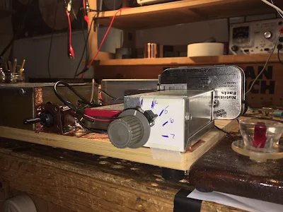
The box with the two grey knobs on the left is the Herring Aid 5, the receiver that took me 38 years to complete. The box on the right is a VFO I originally built for my first BITX40Module -- it started out around 4 Mhz but I pulled turns off the coil until it was in the 40M CW band.  The Altoids in near center has the buffers -- a 40673 MOSFET and a 2n3904 BJT. The box in the back holds the Tuna Tin 2.  There the oscillator has been reconfigured as an amp.  A relay switches the output from the buffers between the receiver and the transmitter.  That big switch in the center switches the antenna and the 12 V for T/R.  The circular black thing is piezo buzzer used for CW sidetone -- I have it glued to the board upside down to keep the volume down. 

The whole thing is mounted on a kitchen cutting board.  A breadboard! 

The most difficult part of all this was getting the needed 800 Hz drop in TX freq on transmit.  You need to do this with a rig like this or else you won't be in the other fellow's passband.  I did a lot of cut and try -- in the end I put a 5 pf cap across the coupling cap from VFO to buffer.  This 5 pf cap switches in on transmit via a small relay.   It works.  I just spoke to N8AFT out in Columbus, Ohio and I was in his passband.  

So five transistors in the receiver, two in the transmitter and three in the VFO/Buffer. So it is the  Fish Soup 10.  

It puts out about half a watt.  On CW.   I am feeling virtuous and vaguely superior. I've made several more contacts.  It all works very well and is a lot of fun. 


Sunday, July 7, 2019

The Fish Soup 7 QRP Rig -- On the Air on 40 Meters (video)


I don't know why, but this weekend I got the urge to get on the air with a very low power homebrew QRP rig.   I reached for my Tuna Tin 2 -- Herring Aid 5 combo.  I call it the Fish Soup 7 (seven transistors in total). 

I first tried to turn this rig into a transceiver by taking the VFO signal from the receiver (it is direct conversion) and using it to excite the Tuna Tin 2, but it just didn't work out.  The oscillator in the Herring Air 5 is very bare bones -- no buffering and an LC circuit that is mostly L (10 uH).  It became very difficult to get a stable amount of CW offset.  So I went back to crystal control for the transmitter.  I did replace the 5K tuning pot in the RX with a 10k 10 turn pot (thanks to W8NSA).  Tuning is now very smooth.  I used my old UK freq counter to monitor my receive freq. (Thanks to Tony Fishpool G4WIF-- back in 2009 he sent me the CMOS chip that brought this counter back to life.) 

I was putting out about 750 milliwatts.  

I had a very quick contest-like contact with K2D -- one of the "13 Colony" stations.  Then a longer chat with Hank K1PUG (see video above).  

I had lost my 7050 crystal, but this morning it re-appeared.  TRGHS. 

As you can see in the video I am using the beautiful VU3XVR  key that Farhan brought me from India. 

This was fun.   I may try to put a VFO of some sort into the TT2, just to get more agility.  But I want to keep things simple.  

Look for me on 7050.  

Thursday, September 21, 2017

Herring Aid Error: C14


Yea, take a look at C14 in the AF amp.   At 1000 Hz 10uF is about 16 ohms.  That would put a serious dent in the AF gain.  And indeed, when I went back to my Herring Aid 5 (38 years from start to finish) and pulled C14 out, there was a dramatic increase in AF gain.  

Mistakes happen, but I wonder if anyone else spotted and reported this one.   Could someone with access to the QST archives check to see if an Erratum was ever published?   The project also appears in the 1977 ARRL book "Understanding Amateur Radio" with the problematic C14.  My guess is that it was just an error in the value of the cap.  

Wednesday, September 20, 2017

Can You See an Error in the Herring Aid Five Schematics?


Something caught my eye this morning.  Please take a look at the audio amplifier stages (Q3 and Q4) on the Herring Aid Five.  Can you see an error? Above is the original schematic from the 1976 QST.  Below is a 1998 update by VK1GB and KI6DS.  I see the same problem in both schematics.  Please let me know if you see an error. 


Saturday, June 24, 2017

Straight Key QRP Homebrew Adventures -- TRGHS


Last Saturday I put the Tuna Tin Two Top together with my Herring Aid Five 38 (year) Special and the Indian key that Farhan gave me.   I discovered that some of my 40 meter CW FT243 crystals had disappeared into the entropy of the shack.  But I was able to find one for 7050 kHz. That was a bit of good luck because it turns out that 7050 is the frequency of a congenial group of operators known as the Straight Key Century Club.  I felt right at home.  I have been inducted.  My SKCC number is 17272.  Very QRP, don't you think?   It is almost a Vanity SKCC.  Clearly, TRGHS.

I have been having excellent luck with this 7 transistor rig.  I have had one contact each day since I put it on the air, all of them in response to my CQ calls.  I've worked:

K1PUG Hank in Connecticut (twice)
W8HOG  Jerry in Ohio
WA4GQG Kevin in North Carolina
WA2AAW Frank in New York
KM4FO Dwight in Kentucky

This morning I added a little piezo buzzer for sidetone.  I am thinking of adding a VFO to the Tuna Tin.

Designer: Douglas Bowman | Dimodifikasi oleh Abdul Munir Original Posting Rounders 3 Column