Podcasting since 2005! Listen to Latest SolderSmoke

Showing posts with label amplifier theory. Show all posts

Thursday, November 21, 2024

Basic Radio Circuitry -- a 1971 film


This 1971 training film is pretty good.  I like how they break the RF circuitry into just four components, then describe the AM receiver stage by stage.  The way they handle diode (envelope) detection is exactly right.  But their description of how mixing moves the incoming signal from the broadcast band to the IF is overly simple, and sort of just repeats the hetrodyne story from music. Real mixing is, of course, more complicated than that, but too complicated for a 15 minute film. 

Tuesday, September 24, 2024

A Clean Vintage Ham Radio Transmitter: The Collins 32S-3


In an article on IMD and splatter,  tech guru Rob Sherwood noted that the cleanest tranmitter he had ever owened was the Colling 32S-3.   Here is the article.  https://soldersmoke.blogspot.com/2024/09/sherwood-its-time-to-clean-up-our.html
In it, you will see thar Rob has the spectrum anayser two tone test to prove his point.  

This got me wondering:  Why was the Collins transmitter so clean.   Today I looked at some ot the tech info on this rig.  I think I have found the answer. The Collins Collectors Association has a great page on the 32S-3: https://collinsradio.org/cca-collins-historical-archives/the-equipment-of-collins-radio/the-grey-boxes/32s-3/

The key lines are these:  


Click on the paragraphs or go to the link for a clearer view 


I think the explanation of Collins'32S-3 cleanliness is due to 1) Thermatrons in the final stages and 2) Negative feedback to take down any IMD products that might appear due to non-linearities in the finals.   

There is nothing magical in that technique.  Heck, we could homebrew that today.  We could build HDR stations (perhaps transistor-tube hybrids) that would be cleaner than their commercial SDR cousins. 

Saturday, September 7, 2024

IMD and Splatter


https://www.robkalmeijer.nl/techniek/electronica/radiotechniek/hambladen/hr/1988/10/page71/index.html

I think the point I was trying to make about the influence of signal strength is here:  

Referring to fig. 1C, note the high level of rf at the 3rd order level - typically 36-dB down. Consequently, there will be rf energy outside the normal 23 kHz passband that will be only 36-dB below the carrier peaks, or about one four-thousandth of the peak power. Not bad if the station is only 25-30 dB out of the noise, but very objectionable if it's 40-60 dB out of the noise.

I think it is supposed to read "2-3 kHz passband" vice "23kHz passband."

I guess the point is that QRP levels of operation can hide a host of ills.   IMD ills.  This makes me wonder about the cleanliness of my own signals.   I will have to do some more careful measurements. 


Saturday, June 1, 2024

Farhan Talks Radio Tech at SolderSmoke HQ (EAST) (TWO VIDEOS!)


Great stuff!  We were really fortunate to have Farhan and Humera visit the SolderSmoke East shack after Dayton and FDIM.  Dean and I had a chance to talk BITX with the creator. Here is the two part video.  Most of the tech talk is in Part II (below).  


Farhan and his zBITX

Dean and Farhan with three sBITXs

Dean's homebrew sBITX

Farhan Phone


Tuesday, April 23, 2024

EXCELLENT Video Series on RF Amplifier Design


Run, don't walk, to this video series by RF MAN.   He is truly, THE MAN!  Pete N6QW found this series, passed it to Dean KK4DAS, who alerted me.  Thanks guys. 

This is a six part video series on how to design an HF 50 watt RF linear amplifier using our beloved IRF-510 MOSFET.  Each video is about 30 minutes long. 

The author (who is this genius?) makes great use of LTSpice.  I have been using this software for years, but still I learned a lot by watching these videos:  AC Analysis.  How to change the values of the things you are measuring.  Even something as simple as drawing a wire right through a component to get leads on both sides.  This is really useful stuff. 

RF Man goes through the whole design of the RF amplifier.  He describes how to use LTSpice to determine input and output impedances (he does this with a NanoVNA in another video).  He talks about the use of negative feedback, and temperature compensation.  There are swamping resistors as Q killers.  This is all great, real-world stuff.  

Especially useful for me was his presentation on how to do "two tone" IMD tests.
  
There is a lot to learn here.  RF Man has a really wonderful way of explaining complex theory, and demonstrating complex tests.   This series makes me want to build a MOSFET amplifier.  

Look for the six parts of this series.  Here is RF Man's YouTube channel: 


Thank you, RF Man! 

Wednesday, March 13, 2024

Using the RF Power Amplifier of the BITX40 Module


PA shematic from the BITX 40 Module
Click on the diagram for a better view

C.F. Rockey W9SCH (who alerted us in SPRAT 22 to the chicken sacrifice option) spoke of transistors that exhibit "quantum mechanical necromancy."  Rockey explained that when this happens, "The transistor simply turns up its toes and dies. Not even an Atomic Physicist can tell you why!"  

This often (very often!) happens with homebrew power amplifiers.  So when we find a good one, many of us stick with it, using the same power amp circuit in rig after rig.  I have done this with the power amplifier from the BITX40 Module. 

Mythbuster (75 & 20 Meter) version (early)  
Click on image for a better view. 
https://soldersmoke.blogspot.com/2021/08/mythbuster-video-13-rf-power-amplifier.html

Same amplifier built into Version 2 of the 15-10 Transceiver 
Click on image for a better view. 

In the build for the 15-10 transceiver you can see some changes.  I used an RD06HHF1 instead of an IRF-510.  I used an 8.1 volt zener diode instead of the regulator chip. I set the bias at around 5.5 volts DC on the gate of the RD06.   I used a smaller, metal can driver transistor (it works fine). I changed the input/output physical configuration between the pre-driver and the driver stages (I think it was kind of goofy the way I had it in the Mythbuster).  Finally, you can see how I used a small piece of copper tape (with conductive adhesive) to shield the line going from the driver transformer to the gate of the RD06.  The wire was too small to use a bit of shielded coax, but I think the copper tape and the copper clad board beneath it work just as well. 

Farhan provided me with some fascinating background on this circuit: 

Bill,

I just saw your post on the bitx40 power amp. The credit must go to Wes for this, it is from the Lichen transceiver described in 6.9 of the EMRFD. I merely copied it with some modifications for it to work with junkbox components.

It bears mentioning that at that time I didn't have a way of generating two tone signal or measuring the IMDR. Those came later when I built my own spectrum analyzer based on Wes and Terry White's spectrum analyzer. It was sheer luck that I picked this power chain that already had careful gain distribution.

For the output, the original build used and LPF with inductors wound on a ballpen shell and TV baluns cores instead of toroids. Again, it was incredibly lucky that they worked at all. 

- f

Friday, September 29, 2023

"The Art of Electronics" #8 -- Why Not a Simple Emitter Follower as The AF Output Circuit?

Click on the image for an easier read

Back when Dean KK4DAS and I were trying to find a suitable AF amplifier circuit for our High School Direct Conversion receiver project, we were debating what to use as the final.  One option was the standard NPN-PNP push-push amplifier (like in Figure 2.53 above)  -- an advantage with this one was that it would not require an AF transformer.  But we decided that this circuit would add complexity to a project that we were hoping to keep very simple. 

Another option was a simple common emitter amplifier with a transformer in the collector circuit.  This worked, and was simpler.  We ordered the transformers.  

In the midst of all this, at the local radio club hams asked us why we just didn't put a single emitter follower at the output to handle the impedance transformation to an 8 ohm speaker (sort of as in Figure 2.52 above).  They were convinced this would work.  I was not so convinced and pointed out that we had never seen such a circuit in any of the ham radio literature.  If this could be done, why hadn't the likes of Doug DeMaw and others used this circuit in their many, many rigs?  

This discussion kind of ended there (we opted for the common emitter transformer circuit), but I have thought about it from time to time.  A couple of weeks ago, when I got the second edition of The Art of Electronics, I found the above discussion of the use of this kind of emitter follower circuit.  You can see why this circuit has not been used.  Just to be sure, I built one in LTSpice.  Sure enough, it takes way too much current.   

Thank you, Horowitz and Hill! 

Friday, September 8, 2023

Why Building for 10 Meters is Harder than Building for Lower Frequencies


Recently my trusty CCI EB63A .1kW amplifier has been in rebellion.  On 10 meters, it now often insists on being an oscillator.   It calms down nicely on 20 meters.  But on 10, it has been a rebellious beast.  

Why is this?  Why would an amplifier that is well behaved and stable on 20 meters behave so badly on 10 meters?    

I used LTSpice to explore the problem.  

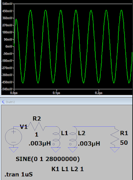
I looked at two ordinary wires.  I gave them each a value of .003 uH.  Very low.  Then I joined them together in a transformer.  I put a 1 volt signal into the primary and looked (in LTSpice) at how much of a signal appeared in the secondary.  First, the result on 14 MHz.  About 250 mV appears on the secondary. 


Now consider what happens at 28 MHz.  Nothing else in the circuit changes.   Just the frequency.


Here we get about 450 mV.  A lot more.   

Realize that my little EB63A amp has lots of wires in it, most of which are ready to serve as primary or secondaries in circuits like this.  Increasing the frequency makes it more likely that a ginal will jump to someplace that it is not supposed to be.  Output will couple to input and the Barkhausen criteria will be met. The amplifier will become an oscillator.   

Of course, something similar happens with capacitive coupling.  Same story:  the higher the frequency, the harder it is to keep the amplifier stable. 

Don't worry:  Improved shielding is saving the day.  The amplifier is now stable on 10.   More about this in the next podcast... 

Tuesday, June 7, 2022

SolderSmoke FDIM Interviews: A BRAVE HAM! Grayson Evans KJ7UM Presents a 50 Watt Amplifier to THE QRP GROUP!

Wow, talk about walking into the lions' den!  Grayson Evans, author of "Hollow State Design" and guru of all things thermatronic, went to FDIM and made a presentation TO THE QRP GROUP on how to build a 50 watt amplifier with a 6146 thermatron.  In New York that would have been called chutzpah.  The QRP ARCI guys seem to have tolerated this QRO-heresy; I'm not so sure the zealots over in G-QRP would have been quite so tolerant.

Grayson gave a nice shout out to SolderSmoke's Pete Juliano.  

And he offered some sage advice to those who live in fear of high voltage:  "Don't touch anything with high voltage on it."  Words to live by my friends.  He even managed to call those who shy away from high voltage "wimps."    This was all very reminiscent of the unforgettable safety advice he offered in his August 2021 interview on Ham Radio Workbench: "Try not to swallow anything, and don't sit on the thermatrons." I mean, who can argue with that? 

You can listen to Bob Crane's interview with Grayson here (about 6 minutes total): 

http://soldersmoke.com/2022 KJ7UM.mp3

Check out Grayson's  Hollow-State Design Book 3rd Edition: tinyurl.com/hollowstatedesign3

Check out Grayson's technical blog:kj7um.wordpress.com


Thanks Bob and thanks Grayson. 


Sunday, June 5, 2022

JFET (Junction Field Effect Transistor) Video -- Part 1


Good video.  I like how he related the real-world device to the Igs graph. Also, note the big variation in MPF-102 parameters.  Stay tuned for Part 2. 

Monday, April 25, 2022

75/20 - 17/12 Two Homebrew Rigs in Scrap-Wood Boxes


I moved the 17/12 Rig off the workbench and placed it (as planned) atop the Mythbuster rig.  Now I have four bands easily accessible.  In these pictures you can see all four bands being displayed on the San Jian Frequency Counters. 

I found a kitchen drain screen that is an ideal cover for the 3 inch speaker in the 17/12 rig. 


I reconfigured the Low Pass filters in the CCI .1 kilowatt amplifier.  I put a 12 meter LP filter in there in place of the 40 meter LP filter (that I haven't been using much). 

I have been working a lot of DX on both 17 and 12.   

Wednesday, April 13, 2022

The 17 & 12 SSB Transceiver -- Circuit and Build Info -- Video #4


I REALLY LIKE THIS RIG. IT IS LIKE A MAGIC CARPET THAT CARRIES MY VOICE ACROSS THE SEAS.

Cutting Display Hole sets off smoke alarm. Reverse Polarity Protection. IF and Crystal Filter at 21.470 MHz 50 ohms! TRGHS! Amp for VXO Carrier Oscillator/BFO. Mic Amp from uBITX. Transmit/Receive switching from mic connector. VFO: NO DIE CAST BOXES! HT-37 Variable Cap, Frequency Shift. BP filters from QRP LABS designs (G0UPL). TIA amp boards from K7TFC. Needed RF amp to hear band noise. BITX40 PA design, but RD006HHF1 instead of IRF510. Should I run receiver input through LP filter? Frequency Readout Story: How to use one San Jian counter on two bands.

Saturday, December 4, 2021

Dean's Supercharged, 16-Watt, Furlough 2040, Simple SSB Rig


'Tis a thing of beauty. 

It is especially appropriate for us to use that Irish phrase because the design of the rig's new final amplifier is out of  Ireland. Our friend Dean KK4DAS added a 16 watt RF amplifier based on a design by EI9GQ to his homebrew N6QW Simple SSB rig.  Note the IBEW label on the top. 

Here is Dean's blog post on this wonderful project (with video and more pictures). 

Dean has it on the air and is getting good reports.  He has clearly come a LONG way from his Michigan Mighty Mite build of just two years ago.  FB OM. 

Here is Dean's build of the EI9GQ 16 Watt Final

Final final assembly! 


Tuesday, October 5, 2021

Dean KK4DAS Builds an EI9GQ 16 Watt RF Amplifier (and Noodles in the Process)


I really like Dean's description of the building process, especially where he describes the need to sit down with paper and pencil for some noodling.   We see that in the picture above.  Too often we hear from guys who seem to be looking for detailed, step-by-step instructions, and then get frustrated and stuck when this kind of detail isn't available. Dean shows what to do in this situation:  noodle! 

Check out Dean's blog post on this project: 


Dean's post made me think about the origin of the verb "to noodle."  We know it has its origins in music.  Google provided this interesting explanation: 

To noodle around on something, while it does make use of the noodle (head), may derive from the regional German nudeln, to improvise a song, or from the late-19th-century Scottish sense of noodling as humming a song to oneself. By 1937, to noodle was to fool around with notes to create music.

We noodle around with parts and schematics to create rigs. 

Tuesday, August 3, 2021

AFTIA! The Audio Frequency Termination Insensitive Amplifier from W7ZOI


It really pays to check Wes Hayward's web site.  I looked yesterday and found something that we really need:  A termination insensitive amplifier for audio frequencies -- an AFTIA.  Just last week I was looking at the AF amplifier of my Mythbuster rig, wishing that it had TIA properties.  Now, thanks to Wes, we have a circuit available: http://w7zoi.net/audio-fba.pdf

And let's not forget that it was Wes Hayward W7ZOI and Bob Kopski K3NHI whose 2009 article alerted us to the RF variety of termination insensitive feedback amplifiers. 

Saturday, March 6, 2021

ZL2CTM's Simple SSB Transceiver


Congratulations to Charlie Morris ZL2CTM for his first contact with his Simple SSB rig.  

There are so many cool things in Charlie's video, starting with his mention of having been woken up early (2 am)  by the very strong earthquake off New Zealand.   Exhibiting true homebrew spirit, Charlie apparently went straight for the shack and worked on his rig.  FB OM. 

Al fresco!  I love the spacious layout on the board and the obvious division into stages.  And I like the wooden board that holds it all together. 

I like the idea of two bandpass filters -- this is simpler than switching one from transmit to receiver.  

Hooray!  Homebrew diode ring mixers!   Yes! 

I think Charlie follows the UK convention with his T/R switch -- they have up as off.  I may be wrong but I think most US homebrewers have up as on, and up as transmit.  Cultural differences. 

Notice Charlie touch-testing the heatsink during that first QSO.  We all do that. 

I like the 24 volts on the IRF-510 drain.  Allison always said that IRF-510s run better at 24V than they do at 12V. 

Of course I disagree a bit on the issue of analog VFOs. But this is just a matter of personal circuit preference. 

Charlie's calculations and notes are really wonderful.  His candid discussion of impedance matching is especially useful.    I think his use of loose-leaf  sheets of paper is wise and it paves the way for a useful folder for each HB rig. 

Here is the introductory video for Charlie's Simple SSB project: 

Here is Charlie's 10 part video series on his simple SSB rig: 

And here is Charlie's YouTube channel: 


Thanks Charlie! 

Friday, August 14, 2020

Tor LB4RG Builds an IRF-510 Amplifier


Click on the link to check out Tor's very FB and artistic video about his homebrew IRF-510 amplifier. 

Very Nice.   Also, check out Tor's FB SolderSmoke hat.  

https://gopro.com/v/bQ1JGOXRrRqrQ

And here is an update from Tor" 

https://gopro.com/v/gv19pDDqQnO1a

Monday, June 22, 2020

Feedback on Farhan's FB Feedback Amp Video


As I said a couple of days ago, Farhan has put out a very informative video on amplifier design. During the video we can see him determine bias, feedback and load levels, then select component values. We then see him actually build the amplifier "ugly style" and use his Antuino to test it.  Fantastic.   

Watch Farhan's video here:  https://www.vu2ese.com/index.php/2020/06/18/feedback-amplifier/


I sent Farhan some of my reactions to the video.  In the hope of stimulating some discussion, I repeat them here: 

___________________

Wow Farhan, I really enjoyed your video and learned a lot.  You definitely have the Knack for explaining this stuff. 

I have been struggling to understand feedback amps for a long time.  I took up this topic on pages 187-190 of the "SolderSmoke -- Global Adventures" book.  I was more focused on the benefits of FB amps, and on how and why feedback affected input impedance.  

 I took notes as I watched: 

-- I liked the fulcrum analogy. 

-- Really wonderful how you describe the selection of components to get desired bias. 

-- Even better when you explain tapping down of RF coil to get 50 ohms to look like 200 ohms. Great stuff. 

-- Standardized on BNC.  FB! 

-- .1uF caps.  Love them!  No argument here! 
 
-- I copied your resistor list.  Will use it with Mouser. 

-- Saving the pigtails.  Indeed!
 
-- I like your ugly "resistors first" technique.  I may have to move away from Manhattan. 

--  Wow.  Ugly circuits IN SPAAAAACE!  FB!
 
--  2N3904   I always think it is EBC when looking at the flat end of transistor with leads facing down. Only had reverse pinout with PN2N2222.  EBC is my usual assumption.
 
-- I still have the big box of trifilars you left me.  I use them.  Thanks!

-- I like that VTVM in your Antuino.   Very handy. Want one!  Also, We need to get the Antuino to go down to below 455 kHz. 

-- I also like your dual Return Loss and SWR display.  I think in terms of SWR.  Return Loss sometimes messes me up. 

-- Didn't know about the Hold and Zoom feature on Antuino. FB.
 
-- Your measurement of the Q of the crystal was awesome.
  
-- I checked my soldering iron temp:  I'm at 480 C   A bit too hot. Will back off. 
 
-- Good description of need for an attenuator at amp output to keep it in Antuino's range.
 
-- As I watched you tug on the components after the solder cooled, I remember an old and silly admonishment from the ARRL Handbook:  NEVER  use solder for mechanical connections.  Ha!  They were WRONG!
 
-- Demonstration of the flatness of feedback was great.
 
-- I found your measurement of impedance using the SWR feature of the Antuino to be very useful.  Is there a chart relating the SWR/Return Loss to actual impedance values? 

-- Loved your description of how output impedance affects input impedance.  That is why you advised use of TIA amps in my DIGI-TIA.   But now I'm thinking that if I can accurately measure impedances of non-TIA amps, I can design L networks that will keep the crystal filter passbands ripple-free, right? 

-- Great explanation of the benefits of the 6 db pads at amp output.  Allison often recommends this. Now I know why. 

-- Wow!  Now I KNOW what that two-tone box you left with me is for!  Now I understand how it can be used to measure IMD on FB amps.  I pulled mine out just as you began to discuss yours.  Really cool. 

Thanks a lot Farhan for doing this.   These videos will be of long-lasting use to homebrewers around the world.  I hope we will see many more VU2ESE videos like this one. 

73  Bill 

Saturday, June 20, 2020

Excellent Video from Farhan on Amplifier Design


Farhan has produced a really excellent video explaining the theory behind the feedback amplifiers that we use in so many of our circuits.  He takes us through the design and construction of these amplifiers, then uses his Antuino network analyzer to test an amplifier  and to measure input and output impedances.  

There is a lot of tribal knowledge and wisdom in this video! 

Check it out here:  

https://www.vu2ese.com/index.php/2020/06/18/feedback-amplifier/

Thanks Farhan! 

Wednesday, March 4, 2020

N3FJZ's Al Fresco. BITX-inspired, TIA. 50 Watt, SSB Rig (Video)


The last blog postings on Rick N3FJZ were in 2015.  Rick sent me a very uplifting reception report, then we had a pretty amazing Homebrew-to-Homebrew contact.  

Paul Taylor VK3HN yesterday alerted me to a new YouTube video that shows the progress Rick has made with his homebrew SSB rig.   

This is a great example of true amateur SSB construction.  Rick is making use of a combination of digital and analog technology.  He is adapting circuitry developed by others and using it to meet his needs.  During the development stage he is keeping the circuit open (Al Fresco) so that he can easily work on it.  

FB Rick.  

Designer: Douglas Bowman | Dimodifikasi oleh Abdul Munir Original Posting Rounders 3 Column