Podcasting since August 2005! Listen to our latest podcast here:

Podcasting since August 2005! Listen to Latest SolderSmoke

Showing posts with label Drake 2B. Show all posts

Sunday, September 20, 2026

Scott K6AUS gets a Drake 2-B from Steve KW4H

 
Serial 10219, after refurbishment by Steve KW4H, with the 2-BQ he sent as well perched on top.


For many years, Scott K6AUS has been doing the mathematical analysis of serial numbers on the Drake 2-B receiver.   His work has been based on mathematics developed during WWII to let the allies know -- just from serial numbers -- how many tanks the Nazis had.  Scott's analysis and the gathering of Drake 2-B serial numbers has been going on since May 2011.  See: https://soldersmoke.blogspot.com/2011/05/how-many-drake-2-bs-german-tank-problem.html
and for a Scott's presentation of the math: 

We were saddened to learn that in spite of all this work, Scott K6AUS did not have a Drake 2-B himself. Steve KW4H stepped forward to correct this.  Steve refurbished a 2-B and sent it to Scott.  FB Steve. See the link above. 

We have been chronicling Steve's work on this partictular Drake 2-B.  Steve also wrote an excellent two part article on this receiver for Electric Radio magazine. Part I recently went out. Part II is coming. 

Thanks to Scott for all his analysis of the serial numbers.  And thanks to Steve for his amazing generosity. 

Saturday, September 19, 2026

Steve KW4H's Restoration of a Drake 2-B -- Part 3 -- Alignment With a New Calibrator

Steve KW4H writes: 

The passband tuner realigning went just fine. To do this, I remove the audio output transformer and push it aside, insulating it from from the components on the chassis underside using a snack-size baggie.  Then, it's necessary to clip the frame of the audio transformer to ground so audio works.  I won't go into the nitty-gritty technical steps, but am just pointing out that in order to align that passband tuner you've got to get that transformer out of the way.  In the 4-line, Drake solved this inconvenience by putting the passband tuner above the chassis, with all of the alignments easily accessible.

 The 2-B is receiving, but not totally realigned yet.  But before we do that, I'm installing a custom-built calibrator/marker generator that will plug right in to the calibrator socket on top of the chassis.  This calibrator provides selectable 25/50/100 kHz spacing (I'll preset it for 50 kHz).  A note for you:  it's operated by the "CAL" switch on the front panel, and is rewired to run on that 9V battery I've installed on the bottom of the chassis (see photo).  The calibrator consumes almost no power when switched on and the battery should last a very long time.  But now you know where the power source is for the calibrator.  I've also attached a photo of the calibrator so you know what it looks like -- for the 2-B, the screw terminal isn't installed on the circuit board -- instead, I wire it directly to a Drake-style 4-prong plug that fit right into that calibrator socket above the chassis.

 The signal from the calibrator will be used for some of the alignment steps, so I like to install it at this phase.

Wednesday, September 16, 2026

More on the Drake 2-B from Steve KW4H -- Part 2 -- Recapping. Cleaning Tubes and Sockets. Tube Tester


The recap is finished.  You can see the new Hayseed Hamfest cap on the chassis, as well as the other new caps.  In these receivers, I also replace every old paper cap -- even the ones in the so-called "hard to get to" places.  On the Drakes, you have to work sideways as many of these boards are vertically mounted.  Drake did that to save space and give their gear a smaller footprint.  The tradeoff is the workbench gymnastics.

The 2-B now has a brand new, 3-wire power cord.  The old bypass caps on the AC line were removed, and a new ceramic safety cap installed on the hot line, between the bottom of the fuse holder and ground.  The original purpose of these capacitors was to filter out household AC line noise.  Such things are rarer these days as household appliances are better designed, but for completeness purposes I think a safety cap on the hot line is reasonable.  

All the tubes were tested and substitutions made where needed.  A word about tube testers:  they're good for discovering major faults, but IMO the best tube tester is the circuit it was designed to run in.  So for these tests I'm just looking for shorts, gas leaks, and obviously weak tubes.  

In addition to testing the tubes, each tube socket is cleaned with a disposable interdental cleaner dipped in 99 percent isopropyl.  Following this, the tube pins are lightly brushed with DeOxit D-100L on the end of a q-tip.  All it takes is just a light film.

The 2-B powered up!  We have contact -- and, of course, some other issues to deal with.  The preselector capacitor was noisy -- the cover was pulled off and it was sprayed and brushed to remove any "whiskers" or other contamination that might cause unwanted conduction between the plates.  It's better now, but I'll keep an eye on it throughout the rest of the process.

Since the passband tuner had to be removed and repaired, it's clear from the sound of things that the passband tuner badly needs to be realigned.  That's going to be done next -- as long as we can jam a signal through the receiver, it's best to realign the passband tuner before swinging around and running through the overall alignment process because it has such a profound effect on the audio and signals.  Also, aligning the passband tuner is logistically more complicated than in Drake's 4-line, as two of the slugs aren't easily accessible.  I'll send some photos later showing how we get around that problem.


Tuesday, September 15, 2026

Steve KW4H's Notes on the Drake 2-B -- Part 1 - Excision of an Unnecessary Mechanical Filter


Obviously I am interested in the Drake 2-B.   Steve KW4H restores rigs of this vintage (similar to our own vintage!).  He has sent me some notes on his work on the Drake 2-Bs.  

Steve writes: 

Attached is a photo of a completely needless 455 kHz mechanical filter I found in this 2B.  Never seen this before, but I found the info -- this was the Henry DMF-2, which was a modification kit sold for the Drake 2A and 2B.  Yet more snake oil sold to the "I need a mechanical filter like a Collins" crowd.  There was a REASON why Drake didn't filter on 455 kHz -- it wasn't nearly as effective as filtering on 50 kHz, which is exactly what the passband filter does.  That, along with the 2-BQ Q-multiplier/speaker makes for a terrific receiver that rivals even many of the modern rigs of today.

That filter is clearly unnecessary, and Steve was completly right in getting rid of it.  Still, it is a Kokusai.  Pete N6QW gave me one of those.  I think I have it in my Mate for the Mighty Midget receiver.   One other note:  As a kid, Steve was in Puerto Rico and operated from the navy base club station KP4USN.  I have that station, during that period, in my log book (I worked KP4USN on April 12, 1974 on 15 CW).  I have to dig up the QSL card to find out if it was Steve, or one of his friends.  

Monday, June 29, 2026

SolderSmoke Podcast #265: AI Pete, WSPR, sBITX, San Diego, Last Ditcher, NYC, 17-12 Fix, MMM Blasphemy, 6T9er, MAILBAG

SolderSmoke Podcast #265 is ready for download. 

Video Version:  https://www.youtube.com/watch?v=-jWYe6NxnJA

Audio Version:  http://soldersmoke.com/soldersmoke265.mp3

---------------------

Travelogue:  Pete to San Diego,  Dean to NYC,  Bill stays home. 

Field Day Report!   Dean?  Pete?  I had a bad back.  Really. 

The importance of "taking a break" discussed on "Hidden Brain" podcast. 

We need new chapters for the FMLA series.  Time to add the CBLA? 

 AI Pete? http://soldersmoke.com/AIPete.mp3

Dean:  WSPR success -- Report

Back on the air with the homebrew sBITX. 

VWS WSPR TX and AMP
KK4DAS WSPR Map
Pete:   Visit to surplus store in San Diego.

The Last Ditcher CW rig.  Frank Jones would approve!  Construction technique combining wooden slats and copper clad boards is FB. 

Homebrew CW rigs -- update. 

Schematics and Co-Pilot

Shameless Commerce Division:   

Mostly DIY RF

Become a Patron through Patreon.  

Do you want an emailed heads up about blog post and pocasts?  Send your e-mail to bill.meara@gmail.com

Please comment on the Podcast (on YouTube or on the blog) and about blog posts (on the blog page). Comments let us know that we are not speaking into the Google void!  

Bill:   Fixing the receiver in my 17-12 rig.  Adding 12 db to the TIA. 

The Open Circuits book.  Eric is the Eric from CuriousMarc.  And he is a ham! 

Blasphemy?  Bill redraws schematic for Michigan Mighty Mite. 

I have 6T9 tube.  I don't really want to build a CW transmitter.  But I may have to. 

Gemini explains "Low Value Content" They see 10,000 posts and assume it is AI Slop.  

Mailbag:  

Wes:  Nice email from W7ZOI. 

Peter Marks VK3TPM fixed the index file (with help from Claude). 

Peter VK3TPM and Paul VK3HN -- Great comments on AI. 

Also Dean KK4DAS and Bob KD4EBM

VK3HN sent FB AI QSL from ZL2BNE (see mine!) 

Bruce KK0S sent two FB AI QSL cards. 

Rogier PA1ZZ -- Sends "The World of El - AI"   IDK. 

Ryan KJ7KVD building a Michigan Mighty Mite (I sent parts) 

Robert W8MOX heard my beacon from the DR to Annandale Va. 

Kirk NTOZ -- The future of ham radio and what went wrong. 

Paul KL7FLR -- The Wizard of Wasila -- Finally 3D  printed a Toroid winder

Charlie NJ7V -- Doing great work over at Red Summit RF.  

Podstatus reports that we are #2 in Ghana!  Hooray for us! 

Farhan VU2ESE -- LARCSet CW mods! 

Walter KA4KXX Homebrew POTA proposal. 

Grayson KJ7UM: Likes Helge's Norwegian paraset

Gerald VA2GJ:  Including DC RX in Canadian license study materials. 

Ron WA6YOU: Spy radios RT-6 and RR-6

Scott K6AUS: https://soldersmoke.blogspot.com/2026/06/update-how-many-drake-2-b-receivers.html We need to send him a 2B! 

Bob W8SX:  FDIM interview with Hans G0UPL.  More to follow.

Sunday, June 28, 2026

Update: How Many Drake 2-B Receivers Were Made? Can Someone Send a Drake 2-B to Scott?

Scott K6AUS has been involved since the very beginning and continues to look at the mathematics: 

https://nomadiq.net/blog/post/how-many-drake-2bs-were-ever-made

Scott has given us a very useful update based on additional serial numbers provided by SolderSmoke listeners. 

How many?  About 11,300.  Check out Scott's page for some interesting mathematical details.  

Thanks a lot Scott!

BTW:  SCOTT K6AUS DOES NOT HAVE A DRAKE 2-B.  THIS IS JUST WRONG! HE HAS DONE SO MUCH FOR THIS RECEIVER!  HE SHOULD HAVE ONE!  IS THERE ANYONE OUT THERE WHO CAN SEND A DRAKE 2-B TO SCOTT?   


Thursday, May 7, 2026

WA4CHQ -- A Virginian QRPer and Homebrewer


This guy had a Drake 2-B,  Heathkit DX-35 with VF-1, and an FT-101EE.   He builds homebrew rigs.  He sailed from England to Virginia on a reproduction of a 1607 ship. 
He notes that Wes W7ZOI was and is his mentor. FB OM.  

Check out his QRZ page:  https://www.qrz.com/db/WA4CHQ 

Monday, May 5, 2025

I admit it. I am not 100% homebrew. I hang my head in shame.


Walter KA4KXX and Mike WN2A and I were recently talking about the degree to which we are 100% homebrew. Both these guys come a lot closer to this goal than I do.  Here is my assessment of my gear: 

I fall far from a state of 100% homebrew grace:  

-- I use commercial power supplies.  I justify this by saying that I could use batteries, and I wouldn't build them. 

-- I use a D-104 with a Tug-8 amp in the base.  I justify this by saying that I COULD homebrew a mic, but I'd just be using a commercial electret element. 

-- My .1 kW amplifier is from a CCI kit.  I find it hard to homebrew 100 watt amplifiers that do not oscillate. Kits make this a bit easier.  

-- I use a K4KIO Hex beam.  I had a homebrew MOXON, but that got destroyed by a Northeaster.  And I have to limit trips up to the roof. Like to zero. (I ask the gutter guy to do this.) 

-- I have a DX-100 and an HQ-100 that I use to check into the Old Military Radio Net on Saturday morning.  I had a DX-100 as a kid, and John Zaruba K2ZA later gave me his dad's DX-100.  That is the one I use. I picked up the Hammarlund HQ-100 in the Dominican Republic in 1993 and have been repairing it ever since.  It is not a great receiver, but it looks good atop the DX-100 and I have a sentimental attachment. 

-- I have an HT-37 and a Drake 2-B that I have had since I was 14 years old. I have a strong sentimental attachment to this gear.  I have worked on most of this old stuff.  

The three SSB dual banders that I am running are mostly homebrew.  The Mythbuster uses a VFO out of the Yaesu FT-101. The 17/12 rig has an LM386 AF Amp. The 15/10 rig has an SBL-1. 

I will try to increase my HB percentage. 

Monday, January 1, 2024

Happy New Year! Straight Key Night at N2CQR (video)


As you know, here at SolderSmoke East HQ we are all about TRADITION.  So last night (New Year's eve) I fired up my venerable HT-37 / Drake 2-B combo and made a few Straight Key Night (SKN) contacts on 40 meter CW.  I was indeed using my straight key.  Video above. 

Also, be sure to check out CuriousMarc's very cool New Year's clock video: https://www.youtube.com/watch?v=YZmEz-Y1FFM

Happy New Year to all.  May you make good progress on your homebrew projects, and may the radio gods act favorably on your behalf.  

73 es HNY de N2CQR 

Friday, November 18, 2022

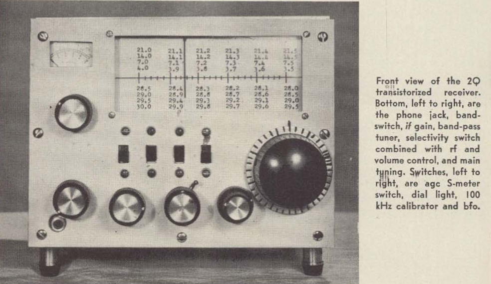
The 2Q -- A Homebrew Solid-State Drake 2-B from 1967

This is really an amazing project.  Way back in 1967 (that's 55 years ago) John Aggers W5ETT of Ponca City, Oklahoma decided to homebrew a solid state version of our beloved Drake 2-B receiver.  Triple conversion.  No crystal filters.  Twenty two discrete transistors and no ICs. Tuned circuits at 50 kHz to provide most of the selectivity.  And he did it.  Just look at the picture above.  It even LOOKS like a Drake 2-B.  

I sent this to our friend Dale Parfitt, W4OP who more recently built a receiver like this.  He too was amazed by this project.  

The article by John Aggers is very clear and provides a lot of good information on how he designed and built this receiver using the technology of 1967 and junk box parts.  I was struck by the lack of diode ring mixers. And I was somewhat taken aback by his use of plug-in socketed transistors.  The AF amplifier is our still-familiar transformer-less push-pull complementary pair design. John did a wonderful job on the mechanical tuning and slide rule mechanism. 

Three cheers for John Aggers W5ETT.  This article is a reminder of the great benefit to the hobby of writing up a project and putting out there in the world.  Here we are, more than half a century later, reading John's article and learning from it.  FB OM.   

https://worldradiohistory.com/Archive-DX/73-magazine/73-magazine-1967/73-magazine-10-october-1967.pdf

Page 8

Monday, September 5, 2022

Why Do Some VFOs Tune More Linearly Than Others?

This has been one of the major complaints about our beloved analog LC VFOs:   The frequency tuning on these circuits is often not linear.  For given amount of VFO frequency dial turn you can get vastly different changes in frequency.  At one end of the tuning range the frequencies are nicely spaced and tuning is easy.  But at the other end of the tuning range all of the frequencies are bunched together.  This is one of the problems that leads some homebrewers to defect to the sad land of "digital VFOs." 

But wait.  It appears that the old designers found a solution to this problem.  Just look at the tuning dial of my HT-37.  The frequencies are all spaced out evenly.  How did they do that? 

I had been thinking that this success may have resulted from Hallicrafters' engineers using the series-tuned Clapp circuit.  Here the main frequency determining element is a series-tuned LC circuit and not the parallel tuned LC circuit that we see in the more commonly used Colpitts circuit.  

But hold on -- how could that be?  The frequency bunching problem that we attributed to the Colpitts circuit must also exist in the Clapp, right?  I went back to SSDRA where there was a good discussion of Colpitts and Clapp VFOs.  The advantage of the Clapp was said to be in its use of a larger value coil which helped minimize the effects of stray inductances.  But there was no mention of the Clapp offering improved linearity in tuning.  

I have in front of me two transceivers:  The Mythbuster uses a 9 MHz Clapp circuit (see below).  The 17-12 rig uses a Colpitts Circuit.  I checked the tuning linearity of both.  Both appeared quite linear in tuning, with no real difference between the two.  

Then I looked at the tuning capacitor in the Mythbuster 17-12 rig.  It came out of an old Hallicrafters transmitter, probably the HT-44.  I looked closely at the stator and the rotor plates.  Both are curved.  I'm guessing that this may yield a more constant change in capacitance for a given movement of the main tuning dial.  

Next I opened up the VFO on the Mythbuster.  (It is the VFO from an old Yaesu FT-101.)  I couldn't see the stators very well but it appears that their shape is different from the square shape we often see in variable capacitors.  Could it be that this variable capacitor was also made to provide linear tuning?  

Back in 2013 Norm Johnson wrote about all this in the Antique Radios.com forum: 

A capacitor that has uniform increase in capacitance with rotation will have the stations at the high end of the band squeezed together. Another type known as the straight-line frequency variable capacitor has, as you might guess, a characteristic that gives even spacing of frequencies with shaft rotation. These were popular in the 1920's but weren't very good for superhets where you needed to have a dual section capacitor that would tune both the RF and local oscillator, and have them track each other properly. The midline variable capacitor is more compatible with a superhet, and easier to make both sections track properly. This is the type that you see in most receivers from the late 1930's to the end of the tube era. They don't have quite the equal spacing between stations across the band that the old straight-line frequency caps had, but they're much better than the variables that change capacitance linearly with rotation.

I wrote an online calculator that helps in the design of the tuning. It shows what frequency range you'll get with a specific type of variable capacitor, including the effects of padder and trimmer capacitors. It also displays a dial scale that shows how the frequencies are lined up accross the dial.
http://electronbunker.ca/eb/BandspreadCalc.html

Steve W6SSP also provided some really good info back in 2013: 

There are three types of open, variable plate caps;
SLC= straight line capacitance where the capacitance varies linearly,
these are the most common and have half-circle plates
SLF= straight line frequency where the plates are tapered to allow
for linear tuning of the frequency
SLW= straight line wavelength, you get the idea...

SLF and SLW caps have oblong plates.

The effect on tuning a receiver can be dramatic. One example is the
Hammarlund SP series of receivers where the ham bands are very
compressed at one end of the tuning range. They used SLC caps
in the VFO. On the other hand rigs like the Kenwood TS-520
and FT-101 series have linear tuning across each band. These use
SLF variable caps. Most old 1920's battery radios used SLW
where stations were identified by their wavelength.
Steve W6SSP

These two variable caps came out of my junkbox.  Both are Eddystones, made in England.  My guess is that the one on the left is SLF.  But could the one on the right (out of an old regen) be SLW?   

The Drake 2-B also has perfectly linear tuning.  I looked at the manual:  "The tuning condenser is of special design..."   I'm guessing that they used an SLF variable capacitor. The 2-B had no need for ganged capacitors -- the "preselector" was tuned via a separate front panel control. 

I looked at the tuning dials on my Hammarlund HQ-100 receiver.   It is fairly linear in its tuning, but not as linear as the HT-37 or the Drake 2-B; on all of the tuning ranges the frequencies seem to spread out a bit at the lower end.  My guess is that Hammarlund used the midline variable described above by Norm Johnson.  The HQ-100 did use a ganged variable cap, with one section tuning the RF amplifier and the other tuning the local oscillator. 

Mythbuster on the bottom.  17-12 rig on the top


Sunday, July 24, 2022

A Surprisingly Good Movie from the Late 1960s: "The Ham's Wide World" (Video)


I found this movie to be surprisingly good.  Narrated by Arthur Godfrey, it features Barry Goldwater, and a lot of other hams.  There is a homebrewer too!  Lots of  old rigs we know and love:  a Drake 2-B, a couple of Galaxy Vs, a Benton Harbor lunchbox, Heathkit SB-series rigs, many Swans, and was that an HQ-170 that I saw in there?  There are also many cool antennas, including a 15 meter quad set up by a bunch of Southern California teenagers. 

Near the end, when they visit ARRL Headquarters, we briefly see none-other-than Doug DeMaw, W1FB!  FB!  

Please take a look at this video and post comments about the rigs, antennas, and radio amateurs that you see in the film. 

Thursday, February 3, 2022

Exorcism Lite -- Spur Suppressed on 17 meter Transmitter -- Split TX/RX Station On The Air


I spent most of January in the tropics, away from my workbench.  This seems to have had a good effect on my 17 meter split TX/RX project.  As I was leaving, heading south,  I was thinking about several difficult options to deal with my spur problem (see previous blog posts). I thought about turning the transmitter into a transceiver by building a receiver board.   I thought about putting San Jian frequency counters on both the transmitter and the receiver, then doing a visual numerical "netting" by just putting the two devices on the same frequency (I actually ordered 3 San Jian counters).   The counter option was even more complicated than it at first seemed -- I would have to build a converter to shift the RX VFO frequency up.  VK2EMU suggested a tube type "Magic Eye" (interesting idea, but also complicated).   This was getting out of hand. 

When I got back home, I took a new look at the problem.   I decided to take one more shot at suppressing the 8th harmonic of the carrier oscillator.  I had already built a new oscillator and buffer using the circuit from Farhan's BITX20.  And I had put it in a metal box.  Now I decided to do three things: 

1) Tighten up the low pass filter at the output of the buffer by moving the cutoff frequency lower (to around 7 MHz) thereby getting a bit more suppression at 41 MHz

2) Try putting a series LC shunt circuit tuned to 41 MHz  at the output of the carrier oscillator (between the oscillator and the buffer). 

3)  Reduce the voltage to the oscillator/buffer.  I have this on a pot, so I can adjust it down to the point where the remnant of the harmonic is no longer audible, while keeping the main carrier osc signal sufficiently strong. 

It seemed to work.  I could now hear the desired frequency for spotting, without the confusing tone from the spur.  

Why had I been able to do this back in 2002 in the Azores using a simple trimmer cap to ground?  My guess is that I was using my Drake 2-B as the receiver.  The trimmer cap to ground may have reduced harmonic output.  And I was probably cranking back the RF gain on the 2-B to the point where I could hear the desired signal but not the remnants of the spur.  I have no RF gain control on the Barebones Barbados receiver that I am using in this project. 

So, what's the lesson from all this?  Well, if you are faced with a serious technical problem, and you find yourself considering complicated and difficult solutions,  go to the Dominican Republic for about a month (especially if it is January or February), and then take another look at the problem when you return.  If you are unable to travel this far or for this long,  taking a walk or taking a weekend break from a troublesome problem will likely have a similar mind-clearing effect. 

The video above shows part of a February 1, 2022 QSO with Gar WA5FWC using the split TX/RX 17 meter rig.  Gar is an amazing long-time SSB homebrewer who got his start with phasing rigs back in the day. 

Saturday, January 1, 2022

Straight Key Night 2021/2022 (Videos) -- Happy New Year!


I made a few contacts on 40 meter CW using my old Hallicrafters HT-37 and Drake 2-B. 

Happy New Year to all!  73   Bill 

Sunday, November 21, 2021

KG7TR's Magnificent 75S-2B Receiver -- Tubes, an Si5351, an Arduino, a Bit of Collins, and a Bit of a Drake 2-B


Oh man, I share this with much trepidation because the last time I posted something about the work of Mike KG7TR,  Pete N6QW said he felt like putting all of his own work in the dumpster, so much better was the artistry of KG7TR.  This receiver is so cool and so well-done that we now  might have to post a guard outside the N6QW shack -- heck Mike even has an Arduino Uno and an Si5351 in there!  Don't do it Pete!

I was led to this magnificent receiver by the very humble 6U8 tube.  Scott  WA9WFA and I have been learning (mostly from Grayson KJ7UM) that the much used and sometimes loved 6U8s (three of them in our "Mates for the Mighty Midget")  might be a bit long in the tooth, old even by Thermatron standards.  I was worried when I remembered that my Drake 2-B has a 6U8 in it -- V2, the first mixer.   So I Googled for more info and was led to this amazing receiver, a 2018 creation by KG7TR.  How did we NOT see this for almost four years?

Here is more info and pictures: 

http://www.kg7tr.com/75s-2b-receiver.html

Here is Mike's write-up of the project: 

http://nebula.wsimg.com/c2281e9bdf3b54da42ca4b0b541b4ec9?AccessKeyId=D18ED10DA019A4588B7B&disposition=0&alloworigin=1

Mike KG7TR's web site:

http://www.kg7tr.com/ 

As for the 6U8s, well Grayson says the tube has been getting something of a bum rap.  And  KG7TR has two of them in this receiver, so I will obviously have to give the 6U8 another chance.  

--------------------

I didn't know that Lew McCoy had his own crystal and crystal filter company: 

http://www.kg7tr.com/the-real-mccoy.html

Wednesday, June 9, 2021

Pete's Drakes


Pete Juliano N6QW has on his blog two very nice videos about the Drake A-line.  

As long-standing fanatical fan of the Drake 2-B, I was struck by the similarities between the 2-B and the R4 seen in Pete's video:  

-- The S-meter is the same. 
-- The passband tuning control and indeed the visible internal circuitry for the passband tuning seem to be the same.  
-- Drake even used the same "hook" for selectivity selection.   

The transceive feature with the T4 seems very nice.  

Pete's first video is above.   Pete's second video, showing his first contacts with the newly acquired A-line, can be seen here: 


Thanks Pete! 

Saturday, April 24, 2021

It's an INVESTMENT!


Exactly what we've been saying about Drake 2-Bs and copies of SSDRA!  

Thursday, October 8, 2020

HA-600A Gets a New Coat of Paint -- After Almost 50 years!


The HA-600A that I picked up last week was looking kind of sorry.  There was a lot of rust on the cabinet.  Below is the before picture. 

I'm not really into cabinetry or radio aesthetics, but it is amazing what a 6 dollar can of spray paint can do. Formula 409 also helps. I moved the light bulbs forward a bit to get more light on that Juliano Blue dial. 

I am really enjoying this radio.  It has brought back many memories.  I think I got one for Christmas in 1972.  I was 14.  I got my Novice ticket on April 27, 1973 and made my first contact on July 19, 1973.  For that first contact I was using an HA-600A and a Heathkit DX-40.  Later I used the Lafayette with a Heathkit DX-100.   The HA-600A was replaced by the far superior Drake 2B on April 11, 1974.  So I used this receiver for more than two years.  

Looking around inside this receiver (and following up with Google) I learned some more about it: 
-- It was made in Japan. 
-- The manual says it has a "mechanical filter" but in fact it has a Toyo ceramic filter.  This may have been just an honest mistake by the folks who wrote the manual -- maybe they didn't understand the difference between the two types of filters. 
-- There is a big difference between the HA-600 and the HA-600A, mostly in the front end circuitry.  The HA-600 has fewer amplifier circuits at the front end.  This probably explains why the HA-600 I picked up did not seem to live up to my memories of my teen-year HA-600A.  

The fellow who gave it to me tells me that it had belonged to the short-wave listener father of a friend of his. 

I know we have a lot of tube-type receivers that are much older than this thing, but I still think it is pretty amazing that this is a receiver that I used almost half a century ago.  And it is still as good as new.