Podcasting since 2005! Listen to Latest SolderSmoke

Showing posts with label Sweden. Show all posts

Saturday, May 11, 2024

Helge SM/LA6NCA Activates Colorburst Liberation Army in Sweden!


FB Helge.   This is really cool.  I didn't realize until I saw the schematic at the end that he was on 3579 kHz -- that is the old color-burst frequency, and now the frequency of the Color-burst Liberation Army. 

It was challenging to do this without sidetone.  But there appears to be a bit of room left in the matchbox -- could he squeeze in a few more components for a rudimentay sidetone?  Maybe just a piezo buzzer across the key? 
VIVA EL CBLA! 

Tuesday, March 23, 2021

Double Sideband Transmitter using Vacuum Tubes -- From Sweden


Tommy SA2CLC has built a really nice DSB transmitter using Thermatrons.  
FB Tommy.  

Thursday, March 11, 2021

Hodgepodge: Moving the Carrier Oscillator Frequency (and a Flashback to 2002) (Video)

As explained in the video, in the course of using my RTL-SDR dongle I noticed that the signal being put out by my Hodgepodge rig had some problems.  There was poor opposite sideband rejection, and in terms of audio quality I has putting out too many lows and too few highs.  I figured the problem was the result of the carrier oscillator frequency being a bit too low, a bit too close to the flat portion of the crystal filter passband.   I needed to move that carrier oscillator frequency up a bit. 


BITX40 Module BFO 

In the actual BITX40 Modules, L5 was replaced by just a jumper wire, and the C103 trimmer was not on the board.  Farhan and his team instead selected X5 crystals to match the passband of the 12 MHz crystal filter. Mine was originally at 11.998653 MHz.  But I wanted to tweak mine a bit -- I wanted to move it up about 500 Hz.  Reducing the capacitance would move the frequency up. Putting capacitance in series with C102 would have the effect of reducing the capacitance in the circuit.  I just removed the jumper wire and used the holes for L5.  First I put in a single 30pf capacitor.  This dropped the capacitance between X5 and ground to 18 pf.  That resulted in too large a shift.  So I added another 30 pf cap in parallel with the first one.  This resulted in a total capacitance from X5 to ground of 26 pf.  This was about right -- the carrier oscillator/BFO frequency was now 11.9991 Mhz.  I had moved the carrier oscillator frequency up by 447 Hz -- just about what I was hoping for.  

This was a very satisfying fix.  it was a chance to put to use experience with other SSB rigs, to make use of the RTL-SDR dongle as a diagnostic tool, and to tinker with the BITX40 Module in the way that Farhan had intended for it to be tinkered with.  

I'd done this kind of adjustment before, but without the benefit of an SDR display.  Below is the story of one such adjustment. 

---------------------------------

A Flashback to 2001-2002
(From my book "SolderSmoke -- Global Adventures in Wireless Electronics")

Now it was time for some debugging and fine tuning.  I needed to make sure that the frequency of the carrier oscillator was in the right spot relative to the passband of the crystal filter.  If it was set too high, the filter would be chopping off high notes in my voice that were needed for communications clarity, and it would allow too much of what remained of the carrier (residuals from the balance modulator) through. If it was set too low, the voice signal transmitted would be lacking needed base notes.  I didn’t have the test gear needed to perform this adjustment properly, but my friend Rolf, SM4FQW, up in Sweden came to my aid.

One night, during a conversation with Rolf, I explained my problem and he offered to help me make the adjustments… by ear.  Performing an electronic version of open-heart surgery, with power on and Rolf on frequency, I opened the case of the new transmitter.  The carrier oscillator has a small capacitor that allows the frequency of the crystal to be moved slightly.  With Rolf listening carefully, I would take my screwdriver and give that little capacitor a quarter turn to the right.  “Better or worse?” I would ask. 

I think this little adjustment session captures much of the allure of ham radio.  There I was, out in the North Atlantic, late at night hunched over a transmitter that had been forged from old Swans and Heathkits, from cell phone chips, and from bits of design from distant members of the fraternity of solder smoke.  Pericles, the source of many of the key parts, was gone.  So was Frank Lee, the amateur whose SPRAT article had inspired the project.  But Rolf and I carried on with the core tradition of the radio fraternity: hams help their fellow hams overcome technical difficulties.  

Tuesday, March 9, 2021

Straight Key Night 2021 at SA2CLC in Sweden


Wow, check out the FB gear of Tommy SA2CLC in Sweden, in use on Straight Key Night 2021. There is some German WWII gear,  a BC-348,  a homebrew transmitter, and some FB QRP kits. 

More on Tommy SA2CLC here: https://www.qrz.com/db/SA2CLC 
The culvert under the road for coax to the antennas is very cool. 

FB Tommy!  A belated HNY to you OM. 

Sunday, August 9, 2020

Presence (Absence?) and Direct Conversion Receivers (with wise comments from Farhan)


Hello Bill,
    I was reading an online article by Wes Hayward, W7ZO  from 1968  about the history of direct conversion receivers (http://w7zoi.net/dcrx68a.pdf)  .  It was linked in an email in qrptech.    It recounts how he had first build a dc receiver with a single diode for the detector, and how microphonic it was, and dissatisfying an experience.   This was in the early days of solid state devices, and so they were hard to come by.   He describes meeting another ham engineer at work Dick Bingham, W7WKR who immediately recognized that what he needed was a diode ring mixer.    The story goes on to describe their experiments, and success at this design.   

  They decided to write up the design for QST.   I won't bore you with the details...the article is well worth reading about how Wes mailed the radio and the design to ARRL, and how it ended up in the hands of a new person on their staff there, Doug DeMaw, W1CER (later W1FB.).  Here is an excerpt from the article describing Doug's reaction to the receiver:

"This was the epiphany, the moment when Doug realized that solid-state technology had produce a new way to build a simple receiver. Doug tuned the receiver higher in the band and found some SSB. Again it was like nothing he had ever heard. It was as if the voice came from the same room. Doug used the term presence in his description."

Here I present the earliest use, that I know of, of presence being used to describe a receiver.    I have to say when I read it, I immediately thought of you guys, and decided to share.

Thanks for all you guys do.
   dave    /nt1u
----------------------------------------------------------
Bill replied:

Thanks Dave.   Yea, that's the 1968 article that launched the use of DC receivers.  I had forgotten about DeMaw's early use of "presence." 

Just to cause trouble, perhaps we should start commenting on "absence"  i.e.  "I dunno OM, I think your rig lacks a bit of absence in the mid-range... turn menu item 63b to ELEVEN!"  
:-)
73 Bill 
----------------------------------------------------------
 

Farhan wrote: 

Mon, Aug 3 at 3:22 PM

When I got my license, my friend Anil SM0MFC was living in Hyderabad. He lent me his HW-8.  I stringed up a 40 meter dipole with a lamp cord and worked with it. Somehow, the combination of the lamp cord length and the 40 meter inverted V made it resonate on 20 m as well. The HW-8 had a nominal antenna tuner and I worked pretty good DX.

Till date, it remains the best receiver that I have used for regular contacts. The only trouble it had was the the MC1496 was a nominal detector, it overloaded heavily with shortwave broadcast stations. There was an unnecessary RF amplifier in the front-end that they could have done without.

I made several direct conversion receivers, but never managed to hang on to any. This makes me want to build one, one of these evenings. I even have a KK7B R1 kit. but real men solder on without any PCBs or even circuit diagram!

A 7/14/21 direct conversion radio that puts out 3 watts of power is what my ideal setup would be. I am not too bothered with the images on CW. I just tune them out in my head. Real soon now, at the moment, i am trying to finish a radio that has been in the works for years.  Finally, I am making some headway.
-f
---------------------------------------------
Farhan of course is no slouch in the DC receiver area.  Years ago he wrote a wonderful post about building a DC receiver with his cousin for her class project: 

Included in this post was a passage that I included in my book  SolderSmoke -- Global Adventures in Wireless Electonics: 
--------------------------
Why build a receiver?
    Why do you want to build it? These are available at the Dubai Duty Free asked Harish, an old friend, when he spotted us struggling over the DC40 one evening. I didn't have an answer to this question and considering the amount of work piled this quarter, it appeared to be a sensible thing to ask.
    I think this question is answered by us all in different ways. My personal answer would be because we human beings are fundamentally tool builders. We have an opposable thumb that allows us to grip the soldering iron.
    For an engineer (by the word ‘engineer', I don't just mean those who have a degree, but anyone who applies technical knowledge to build things) the act of building a receiver is a fundamental proof of her competence and capability. It is much easier to put out 1 watt signal than it is to receive a 1 watt signal.
    A simple definition of a good receiver is that a good receiver consistently, clearly receives only the intended signal, such a definition hides a wide range of requirements. The receiver has to be sensitive enough to pick up the weakest signal imaginable (note: clearly), it has to be selective enough to eliminate other signals (only), it has to be stable enough (consistently).
    For a ham or an engineer, building a usable receiver is a personal landmark. It establishes a personal competency to be able to understand the very fundamental operation of the radio and mastery over it.
--------------------
Bill:  OM Ryan Flowers did a 5 part series on building the DC40.  If you are want to build one, I suggest you use the schematics on Ryan's site.  There was an error in Farhan's original schematic -- Farhan corrected it but some of the incorrect schematics are still floating around the internet.  Here is part one of Ryan's series: 

Farhan's DC40


Sunday, July 12, 2020

A Swedish Homebrew uBITX built in Dubai


It was great to get an update from Martin.  He has moved his workshop from Dubai back to Sweden.  We have seen lots of homebrew BITX monobanders, but very few homebrew multiband uBITXs.  Check out Martin's.  Very FB.   The input from Farhan was very cool, as was Martin's wise decision to follow Farhan's suggestion and to pause construction once the receiver was working.  As Martin put it, "I halted the build for a couple of days and just enjoyed listening."  Thanks for the update Martin. 


Dear Bill and Pete,

Here comes a long overdue update from my workbench, my last update was back in March 2017 when I had completed my first transceiver project.

I did not stop building and quite soon after I completed the CW transceiver Farhan posted the first schematics of the uBitx, why not? Why not get into a multiband CW-SSB transceiver as my next project.

After completing the receive part I was amazed... 


I halted the build for a couple of days and just enjoyed listening.
When it was time to start on the filters and the main RF Amp I sent Farhan an email asking about the way forward, he responded like this on May 17th 2017

"martin,
first, let me congratulate you, i suppose you are the first one to build a ubitx after me! second, i am not happy at all with the transmit line up, the drivers were not doing a good job above 14 mhz. i have replaced the 2n2219s with parallel 2n3904s. i also had to add two more LPFs, for proper harmonic suppression. i am headed for dayton today. once in dayton, i will try to find time to send you the latest circuit diagram. 
once again, congratulations on a wonderfully constructed ubitx."


Wow, what a shot in the arm for a fairly new home brewer!!! I was now back full speed with solder melting. I completed the filter bank and the RF amp, this is where I am starting to move away from the published diagram, I believe it is good to make it your own a little.

The end result was great, I worked many many stations in Europe and Asia with this little machine both SSB and CW.

In 2019 we decided to move back to Europe, the workbench and all boxes with parts and junk together with the rest of the household found their way into a 40ft container and was sent of to Sweden.

The A65DC Laboratories became SM0P Laboratories, the iron is still always hot and there is something brewing here all the time.

Thanks for a brilliant show boys,

Martin SM0P


Tuesday, March 21, 2017

FB IBEW HB DC CW de UAE: A65DC's International Homebrew Rig


Good evening!

After my JOO moment, Bill put me in contact with Pete Eaton, who suggested that I would have a look at the schematics for K4GC 40m CW Transceiver.
And I did, It was just perfect for me, low part count, lots of things done in software!!! Perfect Bryan!


I started off the build and both Bryan and Pete supported me along the way, thank you! 

So here we have it:

The design slowly deviated further and further from the original, but I think I learned quite a lot by starting to make it “my own”.

The Arduino was changed to an UNO, yeah they are clunky and big, but I was not shooting for a pocket-size anyway… and they do have a proper USB port.
The RF-path is now switched by a relay straight after the filter, when the relay is relaxed the antenna is connected to the mixer, when I touch a paddle it connects to the TX circuit.
I have a short hang time from the last key input and it goes back to RX, VOX Delay I guess.

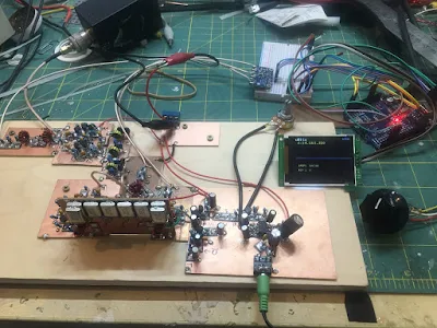
I completed the 700Hz bandpass filter, boy! this makes it a much nicer rig to work CW, I originally I skipped this filter for no good reason? That is the board standing up in the picture.


The TX circuit is a two stage, the first stage is a replica of VK3YE beach40 amplifier circuit, that also uses DB139. The second stage is a spin of the EMRFD Page 2.38 IRF511 Amp.
I have cranked it up to 17w, but it gets too hot too fast, as you can see I don’t have any proper cooling yet, I need to redo this board and plan for the heatsink a bit better.. it is now set around 10w, still getting hot, "599 TU 73”.
To be honest my CW does not go much further anyway, but I guess with this radio now completed I have one more reason to get my speed up.
 I use for convenience both CLK0 and CLK1, when I go into TX I switch off CLK0 and do the keying on CLK1, both transmitter stages are powered up the whole time (until I stop keying as described above)

As the 700Hz filter worked so superb, I decided that I wanted to introduce “modes” to the rig, I can now switch the audio either thru the filters (CW) or straight to the AF amp (AM).
I do enjoy listening around, and we have a lot of AM stations on offer in my region.

I kept the smart RX mute transistor circuit and when I ask the Arduino to change mode, it will mute the receiver quickly, pull the relay and then un-mute again, no ear pain from the loud relay click. (I am happy with that detail).

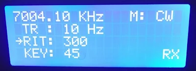
The 2 line display became a four line, and I can change Tuning Rate, RIT, Key Speed and Mode by using only the encoder and the one button built into the encoder.
The front panel sports, on off, Headphones, Paddle and volume, the display and the big knob.
Power connector and USB Port on the side. I did complete the CAT control changes while working on this radio, it now uses the classic Kenwood interface e.g. TS480. (A lot fewer questions from the PC to answer.)

The CAT control works very nice while using N1MM, it works a lot less nice using CQRLog, I guess it has to do with the number of times the software in the PC is asking about things from the radio.
I will look into logic to only worry about incoming serial requests if I have not answered for some time, and never answer while in TX…

By pressing the VFO button a small arrow appears next to TR, if I push again it moves the arrow down to RIT and so on.
if I turn the knob with the arrow standing in front of e.g. KEY it will increase or decrease the KEY speed, when I press again, it will return to frequency control.

Oh, another detail (that I am happy with) while the arrow is in front of the KEY, you can fiddle with the paddle with out transmitting.. practical for testing the speed.

So this is a K4GC transceiver with bits and pieces from VK3YE and bits from the A65DC laboratory in Dubai, truly international.

To trim things in I scheduled a QSO with a local ham here, and things worked very nice, later the same night I made my first “DX” contact with RM2D!!! Moscow!!
What are the odds that a Swedish guy living in the UAE makes the first contact to another Swedish ham who lives in Russia!

73,
Martin A65DC

Wednesday, May 25, 2016

Swedish Michigan Mighty Mite Beacon Project


sTef DL1FDF/VY1QRP alerted us to this multi-band Michigan Mighty Mite beacon project out of Sweden. They certainly have some fine looking rigs! 

Check out the reports:
http://www.radiorud.se/fyren.php


Tuesday, October 14, 2014

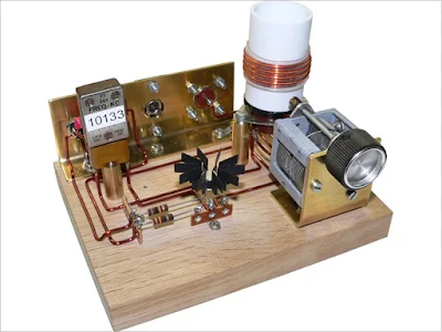
Swedish Mighty Mite


A thing of beauty!  Check out the key! 

What a great diagram.  Schematic included! 


Remnants of mine

Steve "Snort Rosin" Smith's 

More on all this: 


Our book: "SolderSmoke -- Global Adventures in Wireless Electronics" http://soldersmoke.com/book.htm Our coffee mugs, T-Shirts, bumper stickers: http://www.cafepress.com/SolderSmoke Our Book Store: http://astore.amazon.com/contracross-20


Designer: Douglas Bowman | Dimodifikasi oleh Abdul Munir Original Posting Rounders 3 Column