Podcasting since 2005! Listen to Latest SolderSmoke

Showing posts with label Filters. Show all posts

Sunday, December 1, 2024

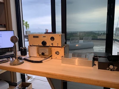
A 40 Meter Direct Conversion Receiver from M0NTV -- With some SolderSmoke Comments


Nick's video appears above. 

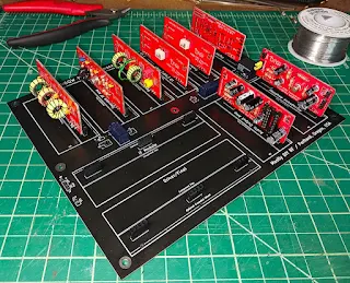
First, let me say FB Nick.   It is nice to see you making use of the AGC amp designed by Wes and Bob,  using the board from Todd's Mostly DIY RF, using a mix of homebrew pads and Me-Squares  from Rex, and finally the Franklin Oscillator that we spent so much time talking about on SolderSmoke.  

But here are some comments:  

-- I still don't think you need that RF amplifier in front of the mixer. And I suspect you would be better off without it.  We did not use one in our high school 40 meter project, and never missed it.  In fact, on one version of the high school receiver I even put in a simple 10k pot as an attenuator (no RF amp).  Even up on 20 meters, I do not have an RF amplifier ahead of the diode ring mixer on either of the Mythbuster rigs I have built.  Nick,  maybe experiment a bit more and try the receiver just going from the BP filter into the mixer and see what happens.  

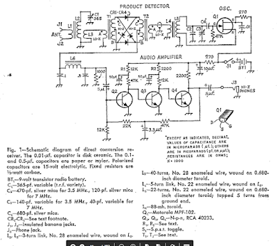
Note that Wes W7ZOI DID NOT have an REF amp ahead of the diode ring mixer in his original 1968 40 meter Direct Conversion receiver (the one that launched the solid-state DC recevier revolution): 


-- The Franklin oscillator is an interesting, but complicated circuit.  The gimmick is, well, gimmicky.  Here is the thing:  You can achieve similar levels of stability using simple conventional, single transistor oscillators.  We dispensed with the variable capacitors, and used PTO--style variable inductors. They worked fine.  This Franklin oscillator still does seem to drift a bit, right?   I would ground the board to the inside of the metal box.    

I would also try putting all the stages on a single ground plane.  This might help.  

Wednesday, October 30, 2024

Bill N2CQR Builds Yet Another Mythbuster Transceiver

 This one is for 20 meters (no need for 75) and will go to the Dominican Republic.

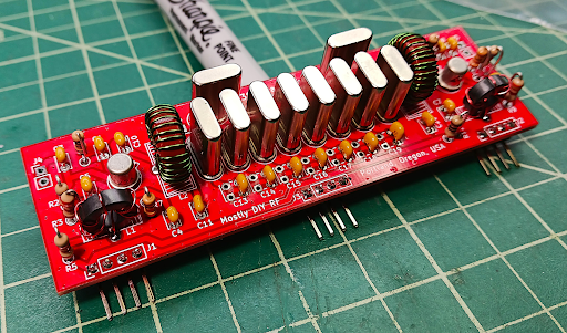
6 crystal filter at 5.2 MHz. VFO from old Yaesu FT-101 Termination Insensitive IF amplifiers using boards from Mostly DIY RF No RF amp ahead of the mixer. First mixer is homebrew diode ring. Bandpass filter has 4 LC circuits. Steep skirts. Low insertion loss. Bal Mod/Product detector has two diodes (singly balanced) Carrier osc is crystal controlled and homebrew. Audio amp starts with a 2N3904 amplifier followed by an LM386 board. Transmitter portion will be done next.

The crystal filter as seen on the Antuino

Filter on the blank board. 

Bandpass filter (-20 db = 0)

VFO box, carrier osc, Bal Mod/Product Detector, AF amps

The Antuino looks at the Crystal Filter


Monday, April 8, 2024

Woebot -- An AI-Based Therapy Bot for Us?

 
This was on 60 Minutes last night.  Of course it made me think of our many "Tales of Woe."  Perhaps this could be of use to us.   But I wonder how the bot would react to our typical problems: 

"I am feeling bad about myself becasue my RF amplifier keeps going into oscillation.  What should I do?"

"My opposite sideband suppression is inadequate because my filter skirts are too wide. What is your advice?" 

"My LC VFO drifts slightly and my SDR-using friends taunt me about this.  I feel dejected.  What should I do?"  

"The Raspberry Pi in my SDR rig is hallucinating and I can't find the needed wisdom files. Is there a support group for this?" 

"I have discovered spurs in the output of my transmitter.  They are 60 db down, but I still can't stop thinking about them.  What should I do?"

I can't help thinking that if Jean Shepherd had access to something like this, his Heising modulator trouble might not have spoiled his date with the girl from his school.  

What do you guys think about the Woebot?  

Monday, April 1, 2024

SolderSmoke Podcast #251 Aurora! CBLA, Winterfest, Legal Action Against SolderSmoke, HB sBITX, SDR, Raspberry Pi, Rounded Passbands, MAILBAG

Aurora Picture by Dean KK4DAS

SolderSmoke Podcast #251  4-1-2024

Audio: http://soldersmoke.com/soldersmoke251.mp3

Videos: Podcast 251 Aurora! CBLA, Winterfest, Legal Threat, sBITX, SDR, RaspPi, Rounded Passbands, MAILBAG (youtube.com)

Travelouge:  Dean goes to the North Pole to see Aurora. 

A CBLA Call to Arms! 

Winterfest.  Lots of goodies.  MXM Industries 40 meter transceiver. 1 dollar. 

Jean Shepherd. Recording of Bill talking to Shep in 1976. 
 https://soldersmoke.blogspot.com/2024/03/listen-to-me-talking-to-jean-shepherd.html

Legal Trouble: Could put us out of operation for a while.  We need listener input. 

November 2023

December 2023

----------------------

Pete's Bench

Homebrew SDR (based on Zl2CTM’s original design) and how good it sounds.

Raspberry Pi Zero W is now working on FT-8 with digital adapter.

Ferrite Cores at Digi-Key (a replacement for the FT-37-43 where  you buy 100 and the price is 21 cents/each)

ADE-6 –great specs in HF but more expensive than the ADE-1

For Pete's recent blog posts, go to this site and click on "Archive" in the right column: 

https://n6qw.blogspot.com/2024/03/march-31-2924-happy-easter-to-those-who.html

----------------

Dean's Bench 

sBITX progress, McGyver-ing a lifted pad, replacing crystal on the CODEC board, sBITX success! See: 

https://kk4das.blogspot.com/2024/03/homebrew-sbitx-tx-modules-pa-lpf-and-mic.html

--------------------

Shameless Commerce Division:  Please use the Amazon link on the blog to start your Amazon purchases. And please consider using Patreon to support the podcast and blog.  We try to send extra content to our Patreon supporters. Mostly DIY RF --  Boards, Kits and Pete's PSSST

---------------------

Bill's Bench

More trouble with the 15-10 rig.  Rounded passbands in 25 MHz filter. See figure 4 in both links: 

https://www.arrl.org/files/file/QEX_Next_Issue/Nov-Dec_2009/QEX_Nov-Dec_09_Feature.pdf

https://www.networksciences.com/pdfs/tutorial.pdf

Experimenting with Balanced Mixers and Product Detectors. Paul VK3HN  Suggests the MC1496 chip; Walter KA4KXX points to SSDRA circuits

But it is on the air!  Using the PA from a BITX40 module and an RD06.  

Put an OLD dial from Pericles HI8P on 15-10 version 1.  Soul in the new machine.

Pericles' Dial on the 15-10 Rig 

Mailbag: 

Grayson KJ7UM's Hollowstate video. 

Mike WU2D's amazing 10 meter DSB transceiver. 

Jack AI4SV (Dhaka Jack) liked video of recent QSO with AzoresDSB rig

Mike AA1TJ and Dave AA7EE on backwaves and 100 uW QRPpppp

Dave G3UUR  on my curved passband problem

Alan W2AEW heard my only QSO with the MXM indsutries SupeRX/TX40

Wes W7ZOI, Mike WN2A, Walter KA4KXX. Farhan VU2ESE on passband, 

Ramakrishnan sent article about Charles Proteus Steinmetz.  Beautiful. 

Justin AC8LV built a receiver!  FB. 

San Francisco QRP:   KDOFNR TouCans Rig, and N6ASD Zinc-Oxide TX

Frank KC8JJL -- Another guy who heard first ham sigs from a homebrew rig. 

Nate KA1MUQ's homebrew thermatron superhet

Dino KL0S sent info on the PAL CB VFO I picked up at Winterfest. Airborne! 

Bob W8SX will be once again doing SolderSmoke interviews at Dayton.  Thanks Bob

Peter VK2EMU  Always good to hear from him.

Tobias Feltus -- Wisdom teeth removed, wondering if he will get sBITX hallucinations...

Rick WD5L continues to work on his Herring Aid 5

Ciprian YO6DXE wants to learn CW. No alerts from his FB Blog!

Todd K7TFC -- Likes CW, says it eliminates the Blah-Blah-Blah 

F1BFU's Amazing PSSST VFO

Tuesday, March 26, 2024

How to Feel Bad about Carrier Suppression (and How to Get Over It)


Version 2 of the 15-10 rig continues to give me trouble.  But I guess it is "good trouble" because I am learning from it. 

You see, after you build an SSB rig, one of the critical alignment steps is the placement of the carrier oscillator/BFO frequency in relation to the filter passband.  (The IMSAI Guy has a good video on this -- see above.)  You want to place this oscillator somewhere on the downward skirt of the passband curve.  This will add to the carrier suppression already done by your balanced modulator.  There will always be some carrier remaining from the balanced modulator -- putting the oscillator frequency on the downward skirt of the filter passband adds to the suppression the carrier remnant.  

But you can't overdo it.   If you place that carrier oscillator frequency too far down on the skirt, you will start to cutoff the low audio frequencies in your transmit and received signals.  You will notice that your once beautiful sounding receiver suddenly sounds tinny and high pitched.  Yuck. 

So you go back to the books and the websites.  You look at the passband promissed by the Dishal software you used to design the filter.  See below:  

Click on the image for a better view

Surely with a passband as nice as that one, you will be able to find the sweet spot where the carrier is suppressed and your audio remains pristine.  

But I couldn't do this with the 15-10 rig.  I was forced to compromise: I had to accept less than optimal carrier suppression for less than optimal low frequency passband coverage.  And here is why:
Click on the image for a better view

The curve above is a much more realistic picture of what my filter passband actually looks like (see NanoVNA picture below).  The curve above is from the AADE software.  I found out that the Dishal software DOES NOT factor in important things like Q or ESR.  Dishal treats all crystals as "loss-less radiators."  So when you get up to 25 MHz where Q is important, AADE and other programs will show you that your passband has become curved.  And you can see how this curvature makes it difficult to get the kind of carrier suppression and audio response we want.  

What my filter looked like in a Nano VNA
Click for a better view

Look, the rigs work OK.  The receivers sound good to me.  The carrier is so far down that no one can hear it.  I have to remind myself that we are using 'SSB-SC" -- suppressed carrier, not eliminated carrier.  I've worked a lot of DX with these rigs.  But still,  I would like to improve the situation.  It kind of bothers me.  Homebrewers will understand. 

I have been experimenting with different balanced modulators.  I started with the simple two diode, single transformer, singly balanced design from Farhan's BITX20.  It works fine.  But I think I get a bit better suppresson from a doubly balanced diode ring.  I may try an NE602 Gilbert Cell.   I may also try to build a higher Q 25 MHz filter using low-ESR surface mount crystals from Mouser.  Stay tuned.  

Thanks to W7ZOI, VU2ESE, WN2A, KA4KXX, KK4DAS, N6QW, W2AEW, and G3UUR for all the good advice and encouragement.  Please put any additional ideas in the comments below.  

Friday, November 10, 2023

SolderSmoke Podcast #249 -- Travel, Pete's 6BA6 rig, Books!, VFOs, SDR, Computers, Spectrum Analysers, Transistor Man! MAILBAG

New VFO for 15-10 Transceiver
Schematic below

SolderSmoke Podcast #249 is available:  http://soldersmoke.com/soldersmoke249.mp3

There is also a video version of this podcast: https://youtu.be/5xyaYivtOhw

Travelogue:  

HAPPY VETERANS' DAY TO PETE AND GRAYSON AND TO ALL THE OTHER VETERANS WHO ARE LISTENING. 

Trip out to San Francisco. Sticker placed on the corner of Haight and Ashbury:  See picture below.  Note other sticker.  Really Groovy! 

Bill's DXCC-100.  DONE.   

Tribal Wisdom:  W1REX on HRWB https://soldersmoke.blogspot.com/2023/11/listen-to-rex-w1rex-lots-of-tribal.html

Pete's Bench:

Pete's 6BA6 rig

Pete's 6BA6 Rig

Pete Re-invents the Shirt-pocket SSB Rig

Pete's remake of the ShirtSleeve Transceiver

Pete Builds Two Computers 

Pete Adds a Second Band to his Homebrew SDR 
 

SHAMELESS COMMERCE DIVISION:  

BEZOS BUCKS ARE BACK!  PLEASE  BUY THERE! >>>>>>>>>>>>>>>>>>>>>>>

Mostly DIY RF:  Work proceeds in the Oregon Silicon Forest on P3ST kit development. Todd is confident the P3ST will be released on December 18th.Many other kits available now:  https://mostlydiyrf.com/ 

Sign up for the newsletter:  https://mostlydiyrf.com/subscribe/ 


Bill's Bench: 

Rebuild of the 15-10 VFO (for improved Dial Spread) (with yet another QF-1 capacitor) https://soldersmoke.blogspot.com/2023/10/dial-scale-linearity-spreading-out.html

Why Building for 10 meters is harder: https://soldersmoke.blogspot.com/2023/09/why-building-for-10-meters-is-harder.html

Copper Tape shielding of 15-10 rig. 

Crushing Spurs with Better Bandpass Filters (see blog post) https://soldersmoke.blogspot.com/2023/09/crushing-17-and-12-meter-spurs-with.html

Another 15-10 rig in the works... for SSSS.   Boards are accumulating... 

More problems discovered with the Herring Aid 5 Receiver . Lots of SS blog posts  Comment from Rick WD5L.  ) https://soldersmoke.blogspot.com/2023/10/a-big-error-discovered-in-1976-qst.html   Did you try to build one?  Did you succeed or did you fail?  Please let us know. 

The Basil Mahon books (blog posts) https://soldersmoke.blogspot.com/2023/11/basil-mahon-is-author-for-us-he.html

The Sunburst and Luminary book of Don Eyles (blog posts) 

The Art of Electronics by Horowitz and Hill (blog posts) 

Spectrum Analysers:  Tiny SA Ultra https://soldersmoke.blogspot.com/2023/09/the-tinysa-ultra-spectrum-analyser-video.html  and Polarad 632C-1; George WB5OYP gave me one of these spectrum analysers  (I NEED a manual! Does anyone have a manual or a schematic? )  : 

Polarad 632C-1

Stabilizing the EB63A (with Pete recommended LP filters from e-Bay. 


MAILBAG:

TRANSISTOR MAN T-SHIRTS!  Thanks to Roy WN3F! 

Todd VE7BPO on AF amplifiers.  Thanks Todd.  

Wes W7ZOI -- Always a privilege to exchange e-mail with Wes. 

E-mail from Jay Rusgrove W1VD. About the Herring Aid 5. 

E-mail from Eamon Skelton EI9GQ!  Amazing! 

HB2HB with Denny VU2DGR https://soldersmoke.blogspot.com/2023/09/hb2hb-contact-with-denny-vu2dgr.html

Nick M0NTV on diode matching for ring mixers: https://soldersmoke.blogspot.com/2023/10/does-matching-matter-diode-matching-for.html

Paul Taylor VK3HN on the new Elecraft CW rig. 

Dean KK4DAS fixed the noise in his Hallicrafters SW receiver.  A long battle, finally won. 

Dean also in contact with G3UUR. 

Ramakrishnan VU2JXN helping me set up a backup of blog on WordPress.  

Mark KA9OOI noticed that SS podcast archive appears gone.  In fact just temporarily relocated to http://soldersmoke.com/podcastarchive.html

(SS PODCAST Archive temporarily relocated to http://soldersmoke.com/podcastarchive.html

Andreas DL1AJG - Crystal radio video. https://soldersmoke.blogspot.com/2023/10/building-crystal-set-videos.html

George N2APB on the Herring Aid 5

Grayson KJ7UM experimenting with Varactors and Thermatrons! 

Thomas K4SWL on Mattia's DC receiver. https://soldersmoke.blogspot.com/2023/10/mattia-zamanas-amazing-direct.html

Bob Weaver of Dial Bandspread Linearity  fame.  Electron Bunker

Mike Bryce WB8VGE QRP Hall of famer -- he too couldn't get the Herring Aid 5 working. 

Kirk NT0Z wrote about the Wayback machine.  But this former ARRL staffer he also tried and failed to get the Herring Aid 5 going.  Way back when... https://soldersmoke.blogspot.com/2015/03/kirks-herring-aid-tuna-tin-and-regen.html


New 15-10 VFO with schematic

Dial Bandspread (Before)

At corner of Haight and Ashbury

Monday, September 4, 2023

SolderSmoke Podcast #248 -- Back from the Summer -- Spurs and Filters, S-meters, 6BA6 mania, Shirtpocket rigs, MAILBAG

The PsssT Kit, coming soon from Mostly DIY RF

SolderSmoke Podcast #248 is available for download: 

Audio: http://soldersmoke.com/soldersmoke248.mp3

Video: (800) SolderSmoke Podcast #238 -- Spurs and Filters, S-meters, 6BA6 mania, Shirt-pocket rigs, Mailbag - YouTube


Travelogue:  Trip to the Dominican Republic 3-9 August.  Thinking about the M0NTV video on mixers...  

Solder Smoke Shack South is almost done.   I am thinking about workbenches, operating tables and antennas.  How high should an electronics workbench be?   Table height?  Or workbench (woodwork) height?  

My son and I went to see "Oppenheimer"  Trinity test scene very cool.  They wanted to see if the gadget would work! 

Is the SolderSmoke blog completely archived on the WayBack Machine?  Please check and let me know.  Thanks. 

Bill's Bench: 

-- I've been working a lot of DX with the homebrew rigs:  Indonesia, Australia, Japan, Hawaii.  Lots of fun.  15 meters has been especially good. But the rigs still need work: 

-- M0NTV's video got me to put TinySA to work.  I found that output from dual banders could be improved.  Spurs and harmonics. Yuck.  I need more TinySA -- ordered the TinySA Ultra. 

-- Allison KB1GMX helped a lot.  EB63A amp was unstable, especially on 10 meters.  Higher frequencies are harder!  Tightened up shielding, negative feedback, and bypassing.  This all helped, but I found that I needed to take the higher frequency LP filters out of the amplifier box.  W3NQN filters are better, with steeper skirts and better 2nd harmonic rejections. NanoVNA proving very useful. https://www.gqrp.com/Datasheet_W3NQN.pdf

-- Also worked on the Bandpass filters for these rigs.  Farhan's comments on skirts of different filter configurations.  Some are "LSB" filters (with steeper skirt at the highest freq) and some are "USB" filters (with the steeper skirt at the lower frequency)  See diagrams on the blog page. So I built USB new filters for 12 meters and for 10 meters. 


-- Danger that my unshielded wooden box rigs might be inviting feedback.  So I shielded the 1510 rig with copper guitar amp tape (conductive adhesive).  Good stuff.  

-- Phase Noise rears its ugly head again.  See blog posts. 

----------------------

SHAMELESS COMMERCE DIVISION:  

Mostly DIY RF getting ready to release PsssT kits.  Target date:  December 18, 2023 (E Howard Armstrong's birthday).  https://mostlydiyrf.com/

Amazon Search box seems to have died.  I can't get it back.  Can anyone tell me what happened?  (There seems to be "explanations" from Amazon about this, but they are written in a strange language that I cannot follow.)  Something similar happened with the Google Ads on this blog page.  Apparently you can't have ads both on YouTube and blogger.  

But hey, there is Patreon for those who want to support the podcast and blog. 

-------------------------

Pete's Bench

An S-meter for Bill? 

6BA6 Mania! 

QRP SSB with 6BA6

Shirtpocket rig re-build

Mailbag: 

Walter KA4KXX has a great article about homebrewing in the September 2023 QCWA Journal.  

 Steve KC1QAY -- Has joined the CBLA.  I sent him a 3579 crystal.  He built a MMM and experienced JOO.  And Allison KB1GMX is in his local radio club.  TRGHS. 

Ajay VU2TGG in Pune, India -- launching a high school receiver effort. 

Denny VU2DGR The Wizard of Kerala: https://soldersmoke.blogspot.com/2023/08/the-wizard-of-kerala-india-denny-vu2dgr.html

Joe VK4BYER working with kids a remote Australian community.  FB. 

Todd K7ZF -- Wants to get into homebrewing. Advised him to start small. 

Dean KK4DAS:  Fixing Hallicrafters Worldwide RX. Ciudad Trujillo!  Got question from Mark in the VWS Makers Group:  HOW DOES Michigan Mighty Mite REALLY Work.  See blog. 

Trevor Woods -- Info on Super Islander Mark IV made in Cuba from old CFL bulbs.  FB. 

Bob KD4EBM sent me some great stuff:  Sony SW receiver,  QCX Mini.  Made a CW contact with the QCX.  Felt virtuous -- it is going to the DR.  Thanks Bob. 

Peter KD2OMV:    One of the guys I worked with the ET-2 transceiver.  Great to hear from him. 

Armand WA1UQO   Richmond area radio museum? https://www.youtube.com/watch?v=BSCmljje1p8

Mike WN2A -- Sent me a great care package with lots of toroids.  A lifetime supply!  Thanks Mike!

Nate KA1MUQ got his Doug DeMaw receiver going after 38 years!  FB.  Been there, done that! 

Tony: G4WIF Liked Valveman video about Gerald Wells.  He visited him! https://soldersmoke.blogspot.com/2023/08/valveman-story-of-gerald-wells.html 

Dean KL7MA  Bill talked to him on 15 SSB.  He had worked Wes W7ZOI!  FB! 

Monday, July 10, 2023

Martein's Bandpass Filters - PA3AKE

Above you can see the really nice 15 meter filter that I built using data provided by Martein PA3AKE. 

https://martein.home.xs4all.nl/pa3ake/hmode/bpf_all.html 

Before I built Martein's filter, my bandpass had been inadequate.  Looking at the signals coming out of the diode ring mixer in my 15-10 rig, I realized that when I was on 15, there would also be an output on 10.  And vice-versa.  These outputs would have to be knocked down by the bandpass filters.  I had been using simple dual tuned circuit filters. But when I looked at the filter shapes of these filters in NanoVNA, I could see that On 15 the 10 meter signal was only down about 20 db.  And on 10 the 15 MHz output was also down only by about 20 db.  That's not enough.  Take a look: 

Before,  with the dual tuned circuit filter

After with Martein's Filter 21.5 Mhz

AFTER with Martien's filter 21.1 MHz

While the earlier filter had provided only about 20 db of attenuation at 28 MHz, Martein's filter provided at least 68 db of attenuation.  That is really nice.  And the passband is nearly flat at 1 db attenuation. 

I built mine using some of the guidance provided on Martiens site.  I did use T80-10 toroids (I got them from kitsandparts.com).  And I did not use copper clad boards.  

One of the charming features if Martein's filters is the total lack of trimmer caps:  Martein recommends tuning the filters by simple squeezing the coils (to increase inductance and decrease frequency) or by spreading out the turns a bit (to decease inductance and increase frequency).  I did the later when NanoVNA showed that I didn't quite have all of the 15 meter phone band on the flat portion of the curve. 

I also like the way Martein provides the values for BP filters for all of the HF ham bands.  Very useful. 

Next I will build one for 10 meters.  And I will probably go back to my Mythbuster and 17-12 rigs and build Martein's filters for these rigs.  
Thanks Martein! 

Friday, October 7, 2022

How the Diode Ring Multiplies by 1 and -1 -- "The Secrets of the Diode Ring" -- Plus another Bandsweep with the DC RX


A deeper look into how the Diode Ring detector works: "the particular go of it." Here I rely on a wonderful diagram from the RSGB. This diagram clearly shows how in this circuit, the switching action of the diodes -- controlled by the VFO -- results in sum and difference frequencies at the output. This is amazingly illuminating. I then tried to build this actual circuit. It works, but I am also getting a lot of AM breakthrough from a local AM station (WFAX) and Radio Marti at 7335 kHz. I will try again. In any case, the diagram shows how the diode ring does its thing! I need to beef up the Band Pass Filter. I tuned around a bit on 40 meters -- you can listen. Students at a local high school have been trying to get the DC receiver I loaned to them going -- they may be confused by the intricacies of SSB tuning. I will see them next week.

Here is the RSGB diagram that reveals the secrets of the Diode Ring.  (Now that could be the title of a book or movie.  I claim the rights to that!)  Click on the image for a better view. 

Friday, September 16, 2022

Fixing Up An Old Homebrew Rig -- Barebones Superhet and VXO 6 Watter

 
I'm not exactly sure why I pulled this old rig off the shelf, but I'll write up what I did -- I often use this blog as a kind of notebook.  I can look back and easily see what I did on my last encounter with the rig. 

The receiver is Doug DeMaw's Barebones (aka Barbados) Superhet.  This was my first superhet receiver. I built in in 1997.   The transmitter was my first real homebrew project -- it is the VXO 6 watter from QRP classics.  I built it in the Dominican Republic, probably in 1993 or 1994.  I built the power supply so that I could say that the entire rig is homebrew. 

This rig is getting a bit long in the tooth:   The receiver is built with 40673 Dual-Gate MOSFETs, an some of the transistor cans have gotten rusty.  The frequency readout on the receiver is the top of a coffee can fitted onto the reduction drive behind the tuning knob from a Drake 2-B (not MY 2B!). 

Here are two 2013 videos that I did on this receiver: 

-- I put the crystal filter back in CW mode.  I had widened it so that I could listen to 20 meter SSB, but I decided to go back to its original configuration.  When I built the receiver in 1987, I didn't characterize the crystals -- I just used the capacitor values that Doug DeMaw had in his article.  I pretty much did that again this time, just putting caps that are close in value to what Doug had.  DeMaw used color burst crystals at 3.579 MHz.  So I guess this would be a GREAT receiver for the Color Burst Liberation Army!  

-- I used My Antuino (thanks Farhan!) to check the passband.  Here is what it looks like.  I just put the Antuino across the 10k resistors on either side of the input and output transformers.  The coil cores had become very loose -- I just tried put them in the right place.  I may need to put some wax in there to allow them to better stay in place. I think they could have used toroids instead -- that would have been easier. One of the transformer connections was open -- they don't work well that way,  once I fixed that, the passband looks like this: 


-- Each of the horizontal divisions is 500 Hz.  The passband is not pretty, but it is OK, and I  didn't feel like doing too much work on this to get it in better shape. 

-- The filter peak was a bit lower in frequency than expected.  I found that trimmer cap C3 in series with the BFO crystal would not allow me to lower its frequency sufficiently.  So I moved C3 to a position in parallel with the crystal.  With this mod, I could get the BFO frequency to 3578.69.  This produces a 690 Hz tone when the received signal is at the peak of the IF passband.  Opposite sideband rejection is quite good. 

March 2013 Rebuild of the VXO 6 watter

-- I didn't have to do any real work on the transmitter.  The RF amplifier in the transmitter had served for a time as the RF amp in by 17 meter DSB rig (I had added a bias circuit, which I removed when I put the amplifier back in Class C).  Some time ago I rebuilt the oscillator circuit (which had been literally cut off the board when I used the amplifier in the DSB rig). 

-- I did have to reconfigure the muting circuit -- the T/R switch in the transmitter switches the antenna and also -- through a two wire circuit -- cuts off 12 V DC to the transmitter when in receive mode. 

-- For sidetone I just put a small piezo buzzer through a 1k resistor between 12 V DC and the key line. 

It all worked fine -- I talked to three stations on the high end of  the 20 meter CW band. 

Wednesday, August 17, 2022

Daylight Again on the Sunrise Net! Walter KA4KXX Builds a PTO


Dear Bill: 

I had never built a PTO, but after reading Farhan's Daylight Again Transceiver article I cobbled one together with parts and pieces I had on hand. My observations so far are as follows. 


1. The frequency-determining capacitors (shown on the schematic as three 470 pf) are very critical, so I feel the usual experimental cut-and-try technique is a must, even using all NP0 and C0G types. 

2. After I built the 2 MHz version like the article (see first photo), the stability was terrific, but when I tried building the companion Daylight Again crystal filter, I was only able to get a bandwidth of 1.6 kHz, which is too narrow for my taste in an SSB radio, so I decided to build the same filter design but with 11 MHz crystals, where I could easily achieve a 2.8 KHz BW. 

3. Therefore, now I needed a higher frequency VFO, so I merely reduced the capacitance (from about 1200 to 370 pf) without changing the coil and I am very impressed with the performance of my 4 MHz PTO (see second photo). The bandspread easily covers the entire 40M band, CW and Phone. 

4. However, whenever I transmit on the 40M Phone band, I like to first set my VFO within 10 Hz of the operating frequency. That way, if I talk for five minutes or so and get up to 15 Hz of drift (which is quite common with many radios when I operate portable outdoors in the sun and wind), it will not be noticable and I avoid receiving any "you are off-frequency" chastising. But the shortcoming I have with this PTO inductor is that the 1/4-20 bolt has a coarse thread, so it is very difficult for an old fellow like me to get within even 20 Hz of a particular frequency just using this common bolt. Therefore I believe a better choice would be the fine thread 1/4-28 two-inch brass threaded bolt which is available from industrial supply houses like McMaster-Carr. However, for CW use or those with a very steady hand, the 1/4-20 works well enough. 

5. I solved my fine tuning problem by adding a varactor circuit using a common 1N914 diode in series with a 100 pf capacitor, operating from 0 to 6 volts. Another advantage to adding this feature is that since I have not so far enclosed my PTO, I can mount the varactor potentiometer several inches from the PTO so my hand capacitance does not affect the frequency like when tuning with the bolt. 

6. An easy way to "do the math" in my case with the common Sanjian counters is to simply create a small lookup table listing half a dozen common frequencies and stick it on the radio. For example, 90% of the time in the morning I am tuned to my favorite SouthCars Net frequency of 7251, so using a BFO setting of 10,999.900, I simply set the PTO to 3,748.90 on the 6-digit 10 Hz resolution counter I normally use (see third photo). 

7. I am currently using my Daylight Again PTO on a daily basis with an NE602 receiver, and I am thinking of adding a locknut to the bolt so it does not wiggle when I jostle or move the radio, essentially giving me a crystal replacement oscillator that I can use for any single 40M frequency. To date I have been able to listen for hours at a time indoors without even any touch-up of the varactor fine tuning. 

8. Also, if continuous frequency readout is desired without building a noise filter circuit board, a separate power supply for the counter is a solution. For portable operation I use Lithium Polymer radio control model airplane batteries which are light, small, and cheap, so one 12V 2000 mAH battery for the transceiver (allows a half hour of transmitting at 15 watts) and a much smaller 12V 350 mAH battery with a series resistor to reduce the current and brightness of the counter has worked well for me. 

73, Walter KA4KXX 
Orlando, FL

Thursday, August 4, 2022

Farhan Takes us Back into the Daylight -- An Analog Rig with a Homebrew Crystal Filter and an LC VFO


There is so much radio goodness in this rig and in the blog post that describes it.  Farhan's blog post will keep us busy for a long time.  There is much to learn there.  But perhaps even more important is his larger view of the role of analog circuitry in ham radio.  Here are a couple of excerpts from his introduction: 

 Here is the memo : The analog never died. The world is analog all the way, until you descend into Quantum madness. The antennas are analog, Maxwell died a content, analog man. Our radios, ultimately, are analog machines and we are all analog beasts too. Amateur Radio technology has evolved into the digital domain. However,  it has only made it easier for us to do analog with computers to simulate and print our circuits.  So, it’s time to bid good bye to our Arduinos and Raspberry Pis and build an Analog Radio for ourselves. So let’s see what we can achieve in hindsight, a return to our native land and a rethink of our approaches. The radio is called Daylight Again, a nod to being back at the FDIM in 2022 after a gap of two years. It is named after the Crosby, Stills, Nash and Young’s song that had been humming all the time while put this radio together, emerging after 2 years of lockdown.  This radio that took two days to come together, no actually two years! That’s: parts of it got built and stowed away, thoughts were struck in the shower, questions popped up during early morning cycle rides and notes and circuits were scribbled in the notebook.  I must take the first of many diversion here: I hope you all maintain a notebook. Write down the date and whatever you thought or did on the bench and the result. Nothing is trivial enough to leave out. Wisdom comes to those who write notes.  I started to build this on Saturday the 14th May and I checked into the local SSB net on Monday morning, the 16th May 2022.

AND

Having clean VFO  is the most important way of increasing the dynamic range of your radio. A free running JEFT VFO that has sufficient power and a good Q components, will be unmatched by any synthesized or direct sampling radios. The math is all on the side of the free running VFO. We are talking -150 db/Hz at 10 KHz spacing, by comparison the Si5351 is -125 db/Hz, it is 300 times worse.

That is just part of the intro.  We should all study the rest of Farhan's blog post very carefully and incorporate the wisdom into our new rigs: 

Here is the blog site: 


Enough of the darkness.  Step into the daylight my friends. 

Sunday, June 19, 2022

A Great Book on Oscillators (Analog LC Oscillators) by John F. Rider (Free!)


Thanks to Peter Parker VK3YE for alerting us to this wonderful 1940 book.  John F. Rider -- a real hero of electronic literature -- does a great job in discussing the practical aspects of oscillator circuits. 

This excerpt from Rider's foreword gives a sense of the approach taken in this book: 


The book covers a lot of material.  In addition to the standard oscillator circuits, he discussed multivibrators, relaxation oscillators and much more.  There is a chapter on magnetostriction in which he shows that this property is the basis for crystal oscillators AND the mechanical filters that we are familiar with.  In fact he seems to take what we would consider a mechanical filter and put it in the grid circuit of a tube to make an oscillator. 

He discussed the modulation of oscillators. He describes the Heising modulator that caused young Jean Shepherd so much teenage heartache.  

Download the book here: 

Saturday, June 11, 2022

Putting the "Mate for the Mighty Midget" Back to Work -- With a DX-100 on 40 Meter AM

After working on it for a while I got so fond of my old Hammarlund HQ-100 that I moved it from the AM/Boatanchors operating position over to a more convenient spot right next to my computer.  This left a big gap on the receive side of the AM station.  

I briefly put my HRO-ish solid state receiver above the DX-100, but I'm afraid that receiver needs some work.  More on that in due course. 

I thought about putting my SOLID STATE Lafayette HA-600A atop the thermatronic DX-100, but this just didn't seem right. The Radio Gods would NOT approve. 

So I turned my attention to the Mate for the Mighty Midget that I built in 1998 and have been poking at and "improving" ever since

This receiver worked, but not quite right. It received SSB stations well enough, but when I turned off the BFO I could no longer hear the band noise. I wasn't sure how well the RF amp's grid and plate tuned circuits tracked.  And I had serious doubts about the detector circuit that Lew McCoy put in there when he designed this thing back in 1966. 

As I started this latest round of MMMRX poking, I realized that I now have test gear that I didn't have in 1998:  I now have a decent oscilloscope.  I have an HP-8640B signal generator (thanks Steve Silverman and Dave Bamford).  I have an AADE LC meter. And I've learned a lot about building rigs. 

FRONT END TRACKING

The MMRX has a tuned circuit in the grid of the RF amplifier, and another in the plate circuit of the RF amplifier.  There is a ganged capacitor that tunes them both.  They need to cover both 80/75 and 40 meters. And they need to "track" fairly well:  over the fairly broad range of 3.5 to 7.3 MHz they both need to be resonant at the same frequency.  

McCoy's article just called for "ten turns on a pill bottle" for the coils in these parallel LC circuits.  The link coils were 5 turns.  No data on inductance was given.  Armed now with an LC meter, I pulled these coils off the chassis and measured the inductances of the coils.  I just needed to make sure they were close in value.  They were: 

L1 was .858uH L2 was 2.709         L3 was .930uH  L4 was 2.672

Next I checked the ganged variable capacitors.  At first I found that one cap had a lot more capacitance than they other.  How could that be?  Then I remembered that I had installed trimmer caps across each of the ganged capacitors. Adjusting these trimmers (and leaving the caps connected to the grid of V1a and V2A, I adjusted the trimmers to get the caps close in value.  I think I ended up with them fairly close: 

C1: 63.77-532 pF          C2 64.81 -- 525.1 pF

I put the coils back in and checked the tracking on 40 and on 80/75.  While not perfect, it was close enough to stop messing with it.  

DETECTOR CIRCUIT


I've had my doubts about the detector circuit that Lew McCoy had in the MMMRX.  In his 1966 QST article he claimed that the circuit he used was a voltage doubler, and that this would boost signal strength.  But I built the thing in LT Spice and didn't notice any doubling.  And consider the capacitors he had at the input and output of the detector:  100 pF.  At 455 kHz 100 pF is about 3500 ohms.  At audio (1 kHz) it is 1.5 MILLION ohms. Ouch.  No wonder years ago I put a .1 uF cap across that output cap just to get the receiver working. 

Scott WA9WFA told me that by the time the MMMRX appeared in the 1969 ARRL handbook, the second "voltage doubling" diode was gone, as were the 100 pF caps.  Now it was just a diode, a .01 uF cap and a 470,000 ohm resistor.  I switched to the 1969 Handbook circuit (but I have not yet changed the 1 meg grid resister to 470k -- I don't think this will make much difference).  Foiled again by a faulty QST article, again by one of the League's luminaries. 

6U8s out, 6EA8s in 

We learned that the 6U8 tubes originally called for by Lew McCoy are getting old and not aging well.  So I switched all three to more youthful 6EA8s.  This seemed to perk the receiver up a bit. 

MUTING from the DX-100

My K2ZA DX-100 has a T/R relay mounted in a box on the back of the transmitter.  When the Plate switch goes up, it switches the antenna from receiver to transmitter.  The box also has a one pole double throw switch available for receiver muting.  I put the common connection to ground, the normally connected (receive position) connect the ground terminal of the AF output transformer to ground -- it is disconnected from ground on transmit.  The other connection (normally open) is connected to the antenna jack -- on transmit this connection ground the receiver RF input connection.  These two steps mutes the receiver very nicely. 

Replacing Reduction Drive

Over the years I have had several different reduction drives on the main tuning cap.  I had a kind of wonky Jackson brothers drive on there that needed to be replaced.  I put in a new one -- this smoothed out he tuning considerably. 

Ceramic Resonator

I never could get McCoy's 455 kc two crystal filter to work right.  So at first I made due with the two 455 kc IF cans.  This made for a very broad passband.  Then I put a CM filter in there.  This was more narrow, but with a lot of loss.  There may have been others.  But the filter spot is currently held by a 6 kHz wide ceramic filter.  This one is my favorite so far. 

Digital Readout

When I was running the DX-100 with the Hammarlund HQ-100 I built a little frequency readout box.  The box was from a Heath QF-1 Q multiplier (I am sorry about this).  The readouts are in Juliano Blue and come via e-bay from San Jian.  I now have it hooked up to the DX-100's oscillator.  I haven't tapped into the MMMRX's oscillator yet. 


Designer: Douglas Bowman | Dimodifikasi oleh Abdul Munir Original Posting Rounders 3 Column