We recently complained that no SolderSmoke Direct Conversion receivers have been built in Japan. So far, no Japanese SS DC Receivers have been built, but Hidehiko JA9MAT has gone a long way in addressing this complaint. In the video above you will see a 40 meter receiver using a PTO and a LONG tuning shaft. There is a wooden base. I see at least three 3D printed coil forms. Hidehiko explains that this receiver has "SA612(DET) + 2N3904 x 2 (Franklin VFO) based with Long Shaft PTO." FB Hidehiko! More from him in the days ahead.
Showing posts with label PTO. Show all posts
Showing posts with label PTO. Show all posts
Thursday, July 23, 2026

Wednesday, May 20, 2026
Farhan Talks LARCSet (CW & SSB) at FDIM (with a Lot of Homebrew Wisdom)

Watch the presentation here: https://www.youtube.com/watch?v=MefojjQ84YY
Farhan made it to FDIM 2026 (he must hold the "distance travelled" record!). We thought he might be talking about the latest version of the digital SDR sBITX, but NO! Farhan talked about the entirely analog LARCSet, a 30 dollar SSB/CW monobander. And in the process he shared a lot of good homebrew history and wisdom. I took notes on the video of his presentation:
-- Farhan recounts his discussion with Steve Hartley, President of GQRP. Farhan said he started to talk about SDR projects, but Steve steered him away from all that. Farhan said he realized that the homes of GQRP members are often small, and projects need to fit into took boxes that are pulled out as needed. There is often not even enough room to mount a screen. Analog rigs just fit better.
-- Farhan talked about the beauty of analog. He also shared some info on the recent timeline of analog rigs, going back to 1976 with the IARU gift kits made available by W1VD. Farhan very kindly mentioned the DC receiver that Dean and I are promoting. He talked about the 2003 BITX 20 rig, and the subsequent uBITX. Farhan talked about the cleanliness of all-analog rigs. "SDR's are a mess!" he said. "With SDRs it is difficult to avoid hash."
-- Farhan said he had trouble measuring the phase noise of the VFO in the LARCSet. He consulted with Wes W7ZOI. Wes told him this was NOT a measurement problem; VFOs have almost no phase noise. The level is even lower than that of crystal oscillators. Of course, crystal oscillators are more stable, but they also have more phase noise.
-- He noted that almost no recent homebrew design does not rely on an Si5351. This, he said, is "not a healthy situation." Indeed.
-- Farhan talked a bit about how Indian regulations seemingly require a deviation from the completly open source ethos. Indian regs require companies to have assets. So the PC board layouts have to remain proprietary.
-- Farhan talked about the sharpness and shape of the BP filter in the LARCSet. I remember talking to him about the shape of my BP filters in my dual banders -- I had to rebuild the filters.
-- On the crystal filters that form the heart of SSB rigs, Farhan noted that cheap low Q crystals often introduce a lot of loss in the filters (that may explain my problem with some styles of computer crystals).
-- A member of the FDIM audience asked about the Sharpie written frequency readout on the LARCset that Farhan showed to the group. Farhan told them that this was the only frequency readout used in the rig.
-- With the LARCSet, Farhan used varactors to vary the frequency. But the varactors he used were cheap but horrible. They varied the frequency as the rig hearted up. The LM386 was the source of heat. He also noted that the cheap varactors, while cheap, did not provide linear frequency readout. Farhan said the varactor scheme was still not perfect; he offered a PTO solution that could be used instead. Three cheers for the PTO!
-- Farhan said the LARCset was really an SSB rig, but when coming to FDIM he said he felt obligated to present a rig that included CW, "or they would throw me out of the room." Farhan described a scheme to generate CW based on what was done with the Atlas rigs.
-- Farhan said the LARCset might even work on 2 Meters. Hmmm.
-- On tuning, Farhan said he used a very large tuning dial (he said it was like a steering wheel) and then recommended the use of a smaller control that could serve as an SSB "clarifier."
-- Farhan pointed out that homebrew rigs are never really done; even decades later, they can still be modified.
Watch the presentation here: https://www.youtube.com/watch?v=MefojjQ84YY
Sunday, December 8, 2024
"The Build Is the Initiation" -- KQ4AOP Offers Encouragement and a PTO Coil Form for Receiver Builders
Scott KQ4AOP put a comment on a recent SolderSmoke Blog post that I found especially encouraging and apprportiate. He was writing about his experience building the High School Direct Conversion receiver.
Scott wrote:
"This was my first receiver build and, it was great fun. When you finish the build and prove you are able to tune through the band, you are welcomed into the secret society! The build is the initiation. I am happy to print and ship the PTO if needed."
The 3d printed form for the tuning inductor is often a show-stopper for prospective builders. Scott offers to print out a form for you, and send it to you.
Scott's mailing address is on his QRZ page. His e-mail address is: streez55@gmail.com
Thanks Scott!
Here is a post I did early this year on Scott's receiver:
Here are the SolderSmoke Posts about this project (keep scrolling -- there are 41 posts!):
Tuesday, March 14, 2023
Fixing the Tuning Problem in the High-School Direct Conversion Receiver (with video)
Here is the problem:
For the capacitive element in the LC circuit we have
essentially two 660 pF caps in series.
This results in a total capacitance of 330 pf. I measured 362 pF.
To get a resonant frequency of 7.0 MHz with 362 pF we need
1.428 uH.
To get 1.428 uH on the PTO coil form we need about 21 turns
of wire.
21 turns on our coil form yields 1.440 uH and resonates with
362 pf at 6.9708 MHz
That’s pretty close to what we need, but the problem
arises when we screw in the brass tuning screw. This reduces the inductance and raises the frequency. Putting the screw
all the way in reduces the inductance to 1.138 uH resulting in a resonant
frequency of 7.8414 MHz. So with a coil
this large (that we must use if we want to tune down to 7.0 MHz) we end up with
a tuning range that is far too large. We
only need 7.0 to 7.3. In effect, this
means that we end up using only a small portion of the tuning range: We can turn the screw approximately 34 times,
but only 6 turns keep us within the range of 7 to 7.3 MHz (the 40 meter
band). There is about 50 kHz per turn of
the dial. This makes tuning
difficult. It becomes more difficult to
separate stations and tune them in. It
would be better if we could tune across the band using more turns of the dial. At least 15 turns of the dial would be
nice: That would mean about 20 kHz per
turn. But how can we do this?

Possible solution #1: Steel screw with tighter pitch on the turns.
Just using a steel screw slows the tuning rate down. In a normal PTO we increase the inductance
(and reduce the frequency) by gradually introducing a ferrous material that
increases the inductance of the coil, pushing the frequency of oscillation
down. But our brass screw is
non-ferrous. This means that putting it
into the core does not change the permeability of the coil. The permeability of brass is the same as that
of air.
What does happen, however, is that introducing the brass screw
into the coil causes currents to flow in the screw. These are called eddy currents. In effect they become shorted secondary coils.
And they have the effect of lowering the
inductance of the coil – this is why the frequency of the oscillator increases
as we screw in the brass screw.
When you use a steel screw you get both effects: As you
screw it in, eddy currents flow in the screw, reducing the inductance and
increasing the frequency of oscillation.
But you are also introducing ferrous material – this pushes in the
opposite direction, increasing induction and lowering the frequency of
oscillation. I think the eddy current
effect dominates, but the increase in permeability pushes in the opposite
direction. This means that with a steel
screw you have to use more turns to cover the same frequency range. And that is what we want.
For example, using the same coil, with screw of the same
thread pitch (the same nuts), with both screws ten turns in, one turn of the
brass screw moved the inductance .014 uH.
The same single turn of the steel screw only moved the inductance .005
uH. So just because of metallurgy, the
steel screw will lead to a lower (better) tuning rate. I used a Hillman 45479 screw
that is steel with a Zinc (anti-corrosive) coating.
But there is more: steel
screws are also available with tighter (#28) thread pitches. The Hillman 45479 uses this tighter thread pitch. This too means that more turns are needed to
move through the same tuning range. Again, that is what we want.
I found that using a steel screw with #28 thread pitch allowed
for the coverage of the 40 meter band in approximately 11 turns of the dial. That is much better than what we got with the
brass screw: About 27 kHz per turn
instead of the 50 kHz per turn that we got with brass. But it is not quite good enough. It would be better if we could use the
entire range of that PTO coil form.
Solution Two: Add
a fixed inductor in series with the PTO coil.
After some noodling, I decided to split up the
inductor: A portion of it would remain
fixed, the other portion would continue to be tunable.
I estimated that I was starting out with a coil of about
1.428 uH. So I just put a 1 uH choke in
series with the variable inductor and reduced the variable coil to about .428
uH (about 9 coil turns). This worked,
but it worked a bit too well! It would
not tune the entire 40 meter band. So I
figured I needed less fixed inductance and more variable inductance. I found an air-cored coil in my junk box and
cut it so that it measured about .650 uH.
I added turns to the variable coil, going to a total of 15 turns. This REALLY worked well and yielded the 26 or
27 turns to tune across 40 meters that you can see in the video.
TWEAKS:
Later, I tweaked it a bit more: With 15 turns of #22 wire on the variable inductor, a steel screw tuned from .791 uH (screw out) to .662 uH (screw in). I put one additional turn on the fixed inductor, making it .749 uH, or about 8 turns of #22 (wound tighter on a cardboard tube from a coat hanger than was the coil on the variable inductor). With these coils I could tune from 6.9772 to 7.386 MHz. That's a bit more than we need but this allows us to keep the tuning away from the ends of the coil where tuning is more likely to become non-linear. I am able to go from 7.0 to 7.3 MHz in 23 turns of the dial. And the tuning is quite linear: The first turn from 7.0 MHz moves the frequency 12 kHz. At the mid-point of 7.150 MHz, one turn of the dial moves the frequency 12 kHz. At the high end, going down from 7.3 MHz, one turn of the dial moved the frequency 11 kHz. That, for me, is VERY linear tuning. You probably will have to adjust the coils a bit (just squeezing the turns together or spreading them apart) to get the tuning range where you want it.
YMMV – Keep it simple!
Like they used to say in the commercials: Your Mileage May Vary. There are many ways of doing this. The objective is smooth tuning across the 40
meter band. I think that by varying the
pitch of the variable coil turns you could get a more linear tuning response (please let us know if you have any luck). You might also be able to get similar results
by changing the amount of capacitance in the feedback network (which is also the
frequency determining element in this simple Colpitts oscillator). But remember that simplicity and a low parts
count were also our objectives in this.
This mod adds only 1 part (the fixed inductor), requires the removal of
some turns from the main tuning cap, and perhaps the replacement of the brass
screw with a steel #28 screw and nuts.

We might present to the student this problem and our search for a solution. This would be a good example of how homebrewers work to make their rigs better and easier to use. It illustrates well the design dilemmas that can come up, and how amateurs like us can come up with solutions.
Saturday, February 25, 2023
Progress Report: High-School Students Build Diode Ring Mixers (Board #2 of 4). Hyderabad Soul Added to the New Machines

Dean KK4DAS works with students
A team from the Vienna Wireless Society was back in the local high school Thursday and Friday of this week, helping the students finish their variable frequency oscillators and build their diode ring mixers. Club President Dean KK4DAS was in the lead, and did an amazing job working with the school and procuring all the needed parts. Mike KD4MM and Don KM4UDX provided patient and understanding help to the students.

Students at work on the receiver
On the oscillators, the students had to add about six parts to install a buffer circuit built around a J310 FET. They also had to replace some of the 3D printed coil forms for the main-tuning variable inductor. (Dean KK4DAS made some really nice forms -- see below.) Several teams of students experiences were very pleased to get their oscillators running.


Manhattan Mixer Pads
Then it was on to the diode ring mixer. We had planned on having the students wind their own trifilar toroids, but we realized that this might be too much -- it would add a lot of time to the build, and would introduce a lot opportunity for error.

One of Farhan's transformers
I remembered that Farhan had given me a big supply of FT-37-43 trifilar toroids that had been assembled in Hyderabad. We decided to use these transformers. We reasoned that this was not a big deviation from our DIY ethos -- after all, we didn't ask the student to wind their audio transformers, nor did they wind the RF choke in the VFO buffer. But we faced a problem: the Hyderabad transformers were all wound with the same color wire on all three turns. This would make it hard for the students to figure out which wire went where (there were 12 such wires on each mixer board!). I figured out how to do this: The night before, I soldered together the center tap wires, and I twisted together the input coil wires. We told the students to first solder the center taps in place, then solder the two free wires to the diode ring, and finally untwist the input coil wires, soldering in these connections. This worked.
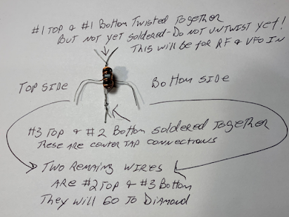
How the transformers were prepped
Before we started, I gave the students a quick class on the essentials of mixers. And I pointed out that we were using transformers made in Hyderabad India and donated by our friend Farhan. I told the students that whenever we include parts given to us by a ham radio friend we are adding "soul to the new machine." Indeed, Farhan's toroids added a lot of soul.
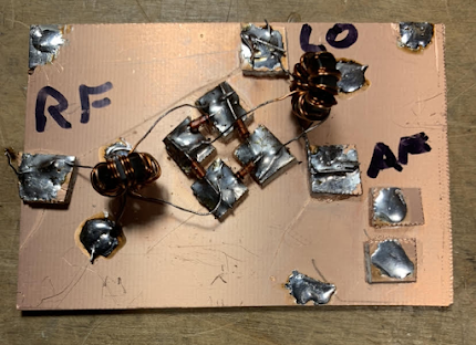
We have been insisting that the students have each stage tested before moving on to the next. This week we used signal generators to put RF and VFO energy into the mixers, and oscilloscopes to make sure that audio was coming out.

One of the test set-ups for the mixers
The students are making good progress. After today's session we did an estimate of where each of the projects stand at this point:
We are building 15 receivers.
Oscillation without the buffer: 11
Oscillation with the buffer: 5
Mixer built and tested (but no diplexer yet): 5
Mixer working, diplexer built 2
Oscillation without the buffer: 11
Oscillation with the buffer: 5
Mixer built and tested (but no diplexer yet): 5
Mixer working, diplexer built 2
During the next month or so the students will build the bandpass filter and the audio amplifier, and put all the boards together to complete the receiver.
Thursday, February 2, 2023
Direct Conversion Receiver Bandscan -- 40 Meters early on a Thursday Morning -- With W1AW/4
I superglued a San Jian frequency counter to the front panel of my High School Direct Conversion receiver. Then I tuned it through the 40 meter band. You can hear the W1AW/4 station. And several SSB stations.
Sunday, January 29, 2023
Rick N3FJZ Builds the Mixer for the High School Direct Conversion Receiver
Wonderful progress from Rick N3FJZ. Having completed the PTO, Rick went on to build the diode ring mixer and diplexer. (See video above.) He then connected these to boards to a band pass filter and an AF amp from previous project. And wow, the resulting receiver sounds really great! I think it sounds better than the ones Dean and I have built.
-- It will be interesting to see how Rick's receiver sounds with the very simple AF amplifier that we are using.
-- We need to get Rick a coil form for the PTO variable inductor! And getting him the PTO form will allow him to dispense with the varactor circuit (which, I must say, is pretty cool).
-- In the PTO, for the coupling capacitor (C15) , I now have a 260 pF NP0 cap. But your .1 uF ceramic disc seems to be doing just fin. So maybe we don't need the NP0.
-- I'm glad that Rick grounded the brass screw. Without that, the hand capacitance effect is bad.
-- I think results will be much the same with the dual tuned circuit bandpass filter that we use. But it will be interesting to see if Rick's triple tuned circuit helps with AM breakthrough (I think I heard Radio Marti when Rick tuned to the top of the band).
-- I haven't had a hum problem and I don't think Dean has either. Dean is running his on two 9V batteries. Maybe that would take care of the hum. Our PTOs are completely Al Fresco!
-- The Traders Net sounds like fun!
Thanks Rick! 73
Saturday, January 21, 2023
A Call for Builders! Please help us Test this Receiver! Please Build this Receiver!

This is the Direct Conversion receiver that Dean and I have built. We plan to have students at a local high school build it, starting in early February. We would like to have some others build it, to make sure that the design is re-producible without problems.
Please build this receiver! But we ask that you build it exactly as per the schematic above and below. Innovation can come later -- for now we just want to make sure this thing works, that there are no errors in the schematic, and that it can be built by the students with minimum woe. Thanks in advance!
Dean or others with 3D printers may be able to supply the plastic form for the PTO inductor.
We know of one other builder, but he is having some trouble. We would like to confirm that this design is sound.
-------------------
Above is the screenshot of the LTSpice model of the 40 meter Direct Conversion receiver that Dean KK4DAS and I have been working on. I will post a larger scale version of the picture below. Click on the images for a better view. Comments welcome. Please let us know if you find any errors or mistakes. Realize that we wanted to keep this all simple, discrete, and entirely analog.
Here (I hope!) is the net list for the LTSpice model:
First, one of the surprising things about the LTSpice model: IT IS ALIVE! I never had a VFO or PTO actually turn on for me in LTSpice. This one did! So I just connected the PTO to the Mixer and the receiver works in LTSpice. I just put an RF signal at the receiver input, and you can see the resulting AF across the 8 ohm resistor at the audio amp output. I was even able to calculate the precise frequency of the PTO: 7078 kHz. As in the real world, in an effort to stabilize the frequency, I changed the capacitors to NP0 in LTSpice. Very cool. Dean joked that all we need is a way to get RF in and audio out and we will have made an SDR receiver.
About the receiver:
-- Four stages that will be built by students Manhattan-style on four copper clad boards: Bandpass filter, diode ring mixer, Permeability Tuned Oscillator (PTO), AF Amplifier.
-- The bandpass filter is a simple dual-tuned circuit device based on the info on the QRP Labs site. (Thanks Hans!) We out a 10k pot as an RF gain control between the antenna and the filter.
-- The mixer is a standard diode ring. We included a diplexer at the output using a circuit from the famous W7EL Optimized transceiver. (Thanks Roy!)
-- The Permeability Tuned Oscillator is a very simple and very stable Colpitts design developed by Farhan VU2ESE. We added a simple FET buffer using the circuit in Farhan's Daylight Again rig. (Thanks Farhan!)
-- The AF amp is a very simple three transistor amplifier based loosely on designs from Forrest Mims and from the Herring Aid 5 receiver. Both these designs use just two stages -- we added a third and put an AF gain pot between the first and the second stages. There is an impedance mismatch between the diode ring and the AF amp, but we found that most of the proposed solutions were more trouble than they were worth, so we left it as is.
--Thanks to Wes W7ZOI for his November 1968 QST article on the solid-state DC receiver. Wes's article inspired our efforts.
Dean and I have both built these receivers. They work very well. Dean has even decoded FT-8 with his. We used Radio Marti at 7355 kHz to test for AM breakthrough -- with the diode ring, the diplexer, and the RF gain control we were able to bring the AM breakthrough down to acceptable levels. You can see many videos of my receiver in action over on my YouTube channel: (355) SolderSmoke - YouTube
Here is a larger image of the schematic (click for a full view):

And here is a nicer schematic done by our friend Walter KA4KXX:

Thursday, December 1, 2022
The 40 Meter Direct Conversion Receiver We Have Been Working On -- Comments Welcome
Above is the screenshot of the LTSpice model of the 40 meter Direct Conversion receiver that Dean KK4DAS and I have been working on. I will post a larger scale version of the picture below. Click on the images for a better view. Comments welcome. Please let us know if you find any errors or mistakes. Realize that we wanted to keep this all simple, discrete, and entirely analog.
Here (I hope!) is the net list for the LTSpice model:
First, one of the surprising things about the LTSpice model: IT IS ALIVE! I never had a VFO or PTO actually turn on for me in LTSpice. This one did! So I just connected the PTO to the Mixer and the receiver works in LTSpice. I just put an RF signal at the receiver input, and you can see the resulting AF across the 8 ohm resistor at the audio amp output. I was even able to calculate the precise frequency of the PTO: 7078 kHz. As in the real world, in an effort to stabilize the frequency, I changed the capacitors to NP0 in LTSpice. Very cool. Dean joked that all we need is a way to get RF in and audio out and we will have made an SDR receiver.
About the receiver:
-- Four stages that will be built by students Manhattan-style on four copper clad boards: Bandpass filter, diode ring mixer, Permeability Tuned Oscillator (PTO), AF Amplifier.
-- The bandpass filter is a simple dual-tuned circuit device based on the info on the QRP Labs site. (Thanks Hans!) We out a 10k pot as an RF gain control between the antenna and the filter.
-- The mixer is a standard diode ring. We included a diplexer at the output using a circuit from the famous W7EL Optimized transceiver. (Thanks Roy!)
-- The Permeability Tuned Oscillator is a very simple and very stable Colpitts design developed by Farhan VU2ESE. We added a simple FET buffer using the circuit in Farhan's Daylight Again rig. (Thanks Farhan!)
-- The AF amp is a very simple three transistor amplifier based loosely on designs from Forrest Mims and from the Herring Aid 5 receiver. Both these designs use just two stages -- we added a third and put an AF gain pot between the first and the second stages. There is an impedance mismatch between the diode ring and the AF amp, but we found that most of the proposed solutions were more trouble than they were worth, so we left it as is.
--Thanks to Wes W7ZOI for his November 1968 QST article on the solid-state DC receiver. Wes's article inspired our efforts.
Dean and I have both built these receivers. They work very well. Dean has even decoded FT-8 with his. We used Radio Marti at 7355 kHz to test for AM breakthrough -- with the diode ring, the diplexer, and the RF gain control we were able to bring the AM breakthrough down to acceptable levels. You can see many videos of my receiver in action over on my YouTube channel: (355) SolderSmoke - YouTube
Here is a larger image of the schematic (click for a full view):
And here is a nicer schematic done by our friend Walter KA4KXX:
Saturday, November 19, 2022
A 1966 73 Magazine Article on a Homebrew Permeability Tuned Oscillator (PTO)

Lewis opened his article with this:

Clearly, this guy was one of us!
His article is filled with good practical advice on VFO construction, with a special focus on PTOs. I was intrigued by the way his PTO mechanism allowed for the use of a reduction drive. This would help us avoid the indignity of attaching a digital frequency counter to such a quintessentially analog device.
https://worldradiohistory.com/Archive-DX/73-magazine/73-magazine-1966/73-magazine-04-april-1966.pdf
Page 30.
Thanks to Michael (VE2BVW ?) for suggesting that I dig up some old 73 Magazine articles on PTOs. A quick search revealed that there weren't many. If anyone out there knows of good PTO articles in the ham or EE literature, please let me know.
Tuesday, November 15, 2022
Amazingly Cool MONTV Video on Direct Conversion Receivers with Glue Stick PTOs
I think this is one of Nick's best videos. And he has made a lot of good ones.
This is a really excellent description of how a Direct Conversion receiver works. But more importantly Nick really captures the joy of building one of these receivers using discrete, analog components, including a Permeability Tuned Oscillator made from our beloved Glue Sticks.
Extra mojo comes in the form of a mixer designed by Pete Juliano using J310s to simulate a 40673 dual gate MOSFET. Fantastic. Icing on the cake comes from a W8DIZ AF amp out of SPRAT magazine.
There is a grand finale. I won't spoil it. Watch the video. Suffice it to say that Farhan would be pleased with this.
Great stuff. Thanks Nick!
A Treasure Trove of Permeability Tuned Oscillator (PTO) Info and Links (Plus Info on Direct Conversion Receivers)

There is really great info on this page, and even more in the links at the bottom of it. While the page is about PTOs, the links often discuss their use in Direct Conversion Receivers. I really liked the Tin Ear receiver. And it was great to again come across the work of Alan Yates VK2ZAY. Alan very admirably admits that laziness caused him to use an LM386 audio amplifier in place of a more virtuous discrete transistor design.
https://qrpbuilder.com/pto_mechanism
I bought one of the qrpbuilder PTO kits and I will soon put it together. I have been having good results with a Glue Stick PTO and with a brass screw PTO form designed by Farhan and 3D printed for me by Dean KK4DAS.
LET'S GO PTO!
Friday, October 28, 2022
SolderSmoke Podcast #241 Mars, Direct Conversion, PTOs and Glue Sticks, Anniversary of the BITX20, Multus Proficio SDR, Boatanchor Station, MAILBAG

The board I use to test DC RX circuits
SolderSmoke Podcast #241 is available
Audio (podcast): http://soldersmoke.com/soldersmoke241.mp3
Video (YouTube): (215) SolderSmoke Podcast #241 October 28, 2022 - YouTube
Introduction:
Back on Mars. Opposition
approaching. I have a Mars filter. And (like T.O.M.) a Mars
globe.
N2CQR DXCC done
SolderSmoke in the WayBack
Machine
Sticker news
PARTS CANDY -- Don't Scrimp with a Crimp!
Bill's Bench
School DC RX projects -- in
Hyderabad and Northern Virginia.
Direct Conversion Receivers --
Keeping it Simple, Learning a Lot. A step beyond the Michigan Mighty Mite.
Do we really need 100db? Do we really need to shield VFOs? Farhan's
super-simple and stable Colpitts PTO. Audio amps, 1000-8 transformers and
rolling your own LM386
PTOs and Glue Stick PTOs.
Paul Clark WA1MAC. Brass vs. Steel bolts. #20 thread vs. #28
thread. Backlash Blues. The best Glue Sticks.
2 meters and the VWS.
Bill has a Baofeng.
SHAMELESS COMMERCE:
MOSTLY DIY RF
Pete's Bench
20th Anniversary of the
BITX20 Pete's early BITX rigs.
Computer Woes
The Multus Proficio SDR rig
Simple SSB in China
BA7LNN
Things of beauty: Tempo
One, NCX-3 and a SBE-33
MAILBAG
-- NS7V is listening.
-- Graham G3MFJ
sent SPRAT on a stick.
-- Nick
M0NTV FB Glue Stick and 17 Shelf videos.
-- Dino KL0S
HP8640 Junior
-- Mark AA7TA Read the SolderSmoke Book
-- Steve EI5DD Connaught
(Ireland) Regional News
-- Dave
K8WPE Planting the seeds of ham radio
interest
-- Peter VK3YE
Ruler idea on PTO frequency readout
-- Michael AG5VG Glue
Stick PTO
-- Tobias A polymath with UK and Italy
connections. And cool tattoos.
-- Alain
F4EIT French DC receiver
-- Michael
S. was in USMC, working on PCM/TDM gear
-- Alan Yates
writes up Amazon transformer problem
-- Todd VE7BPO, Dale W4OP, Wes W7ZOI
-- Farhan VU2ESE
sent me an sBITX
-- Todd K7TFC The Revenge of Analog
-- Jim Olds Building QRP HB gear

The Multus SDR rig Pete discussed

The older rigs Pete mentioned

My version of DC RX that Farhan is working on

My PTO with VK3YE's ruler frequency readout
Wednesday, October 12, 2022
World's Most Interesting Man on PTOs and Glue Sticks

I mean, if they are good enough for the Dos Equis guy, maybe we should give them a chance.
Monday, October 10, 2022
Listening on 40 with a Glue Stick PTO in a Direct Conversion Receiver; Some PTO History
Thanks to Paul WA1MAC for this idea. He first shared it with us via the SolderSmoke mailbag in 2008! Sorry it took so long for me to try one Paul.

The PTO itself is an old idea of course. Here is an article from 1966:
OM faced the problem of having to keep track of frequency while turning the dial many times. He was hoping to use a turns counter -- in 1966 we didn't have the San Jian frequency counters. I note that his PTO looked a lot like the one KK4DAS 3D printed for me (using file from Farhan).
And some background on PTOs: https://sites.google.com/site/randomwok/Home/electronic-projects/permeability-tuners-last-stand
Sunday, October 9, 2022
Paul Clark's Dollar Store PTOs made with Glue Sticks or Chap Sticks
A few weeks ago Pete Juliano and I got some e-mails from Paul Clark about his use of Chap Sticks and Glue Sticks (acquired at a Dollar Store!) in Permeability Tuned Oscillators.
Dean KK4DAS, Mike KA4CDN and I had been experimenting with PTOs following Farhan's use of one in his new Daylight Again transceiver. We are also looking at simple circuits for use in Direct Conversion Receiver builds for high school students.
Yesterday, I noticed a Glue Stick on the floor under my bench. TRGHS. I built one of Paul Clark's PTOs and used it with the circuit from Farhan's Daylight Again rig. For the ferrous material, I just glued (!) a .5 inch toroid (I think it is #7 material) onto the moving internal part of the glue stick. For the coil I used a total of 9 turns of #20 wire, with a tap at 2 turns. You can see the results in this video.
I think it is really useful, a very nice way to get good frequency control using an item available in most super-markets (I bought two glue sticks at Harris Teeter yesterday!). This continues a long ham radio tradition of using household items for ham projects -- we started with breadboards.
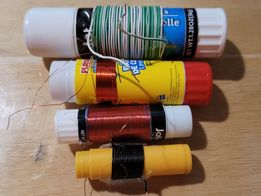
Some of Paul's coils:
Some of Paul's data:
Here's the data I got in testing these on the NanoVNA:
Dollar Store PTO Forms in 3 sizes
Small Jot Glue Stick (8 for $1.25!)
1 3/8" of #30 enameled close wound
waiting brass tubing to fit cup
80pf
2.980mhz with no core, I'm waiting brass tubing to fit this one (we have no hobby stores around here anymore that stock the K&S music wire and brass tubing assortments)
35.65uh
Medium Playschool Glue Stick
36t #30 enameled
1/2" copper water tubing
80pf
2.96m-3.380m
36.13uh-27.72uh
Large JOT Glue Stick
1/2" copper water tubing
80pf
28t #24 insulated
4.995m-5.625m
12.69uh-10.00uh
Wednesday, August 17, 2022
Daylight Again on the Sunrise Net! Walter KA4KXX Builds a PTO
I had never built a PTO, but after reading Farhan's Daylight Again
Transceiver article I cobbled one together with parts and pieces I
had on hand. My observations so far are as follows.
1. The frequency-determining capacitors (shown on the schematic
as three 470 pf) are very critical, so I feel the usual experimental cut-and-try
technique is a must, even using all NP0 and C0G types.
2. After I built the 2 MHz version like the article (see first photo), the stability was terrific,
but when I tried building the companion Daylight Again crystal filter,
I was only able to get a bandwidth of 1.6 kHz, which is too narrow for my taste
in an SSB radio, so I decided to build the same filter design but with 11 MHz crystals,
where I could easily achieve a 2.8 KHz BW.
3. Therefore, now I needed a higher frequency VFO, so I merely
reduced the capacitance (from about 1200 to 370 pf) without changing
the coil and I am very impressed with the performance of my 4 MHz PTO (see second photo).
The bandspread easily covers the entire 40M band, CW and Phone.
4. However, whenever I transmit on the 40M Phone band, I like to first set my VFO
within 10 Hz of the operating frequency. That way, if I talk for five minutes or
so and get up to 15 Hz of drift (which is quite common with many radios when
I operate portable outdoors in the sun and wind), it will not be noticable and I avoid
receiving any "you are off-frequency" chastising.
But the shortcoming I have with this PTO inductor is that the 1/4-20 bolt has a coarse thread,
so it is very difficult for an old fellow like me to get within even 20 Hz of a particular frequency
just using this common bolt.
Therefore I believe a better choice would be the fine thread 1/4-28 two-inch brass threaded
bolt which is available from industrial supply houses like McMaster-Carr.
However, for CW use or those with a very steady hand, the 1/4-20 works well enough.
5. I solved my fine tuning problem by adding a varactor circuit using a common
1N914 diode in series with a 100 pf capacitor, operating from 0 to 6 volts.
Another advantage to adding this feature is that since I have not so far enclosed
my PTO, I can mount the varactor potentiometer several inches from the PTO so
my hand capacitance does not affect the frequency like when tuning with the
bolt.
6. An easy way to "do the math" in my case with the common Sanjian counters
is to simply create a small lookup table listing half a dozen common frequencies
and stick it on the radio.
For example, 90% of the time in the morning I am tuned to my favorite SouthCars
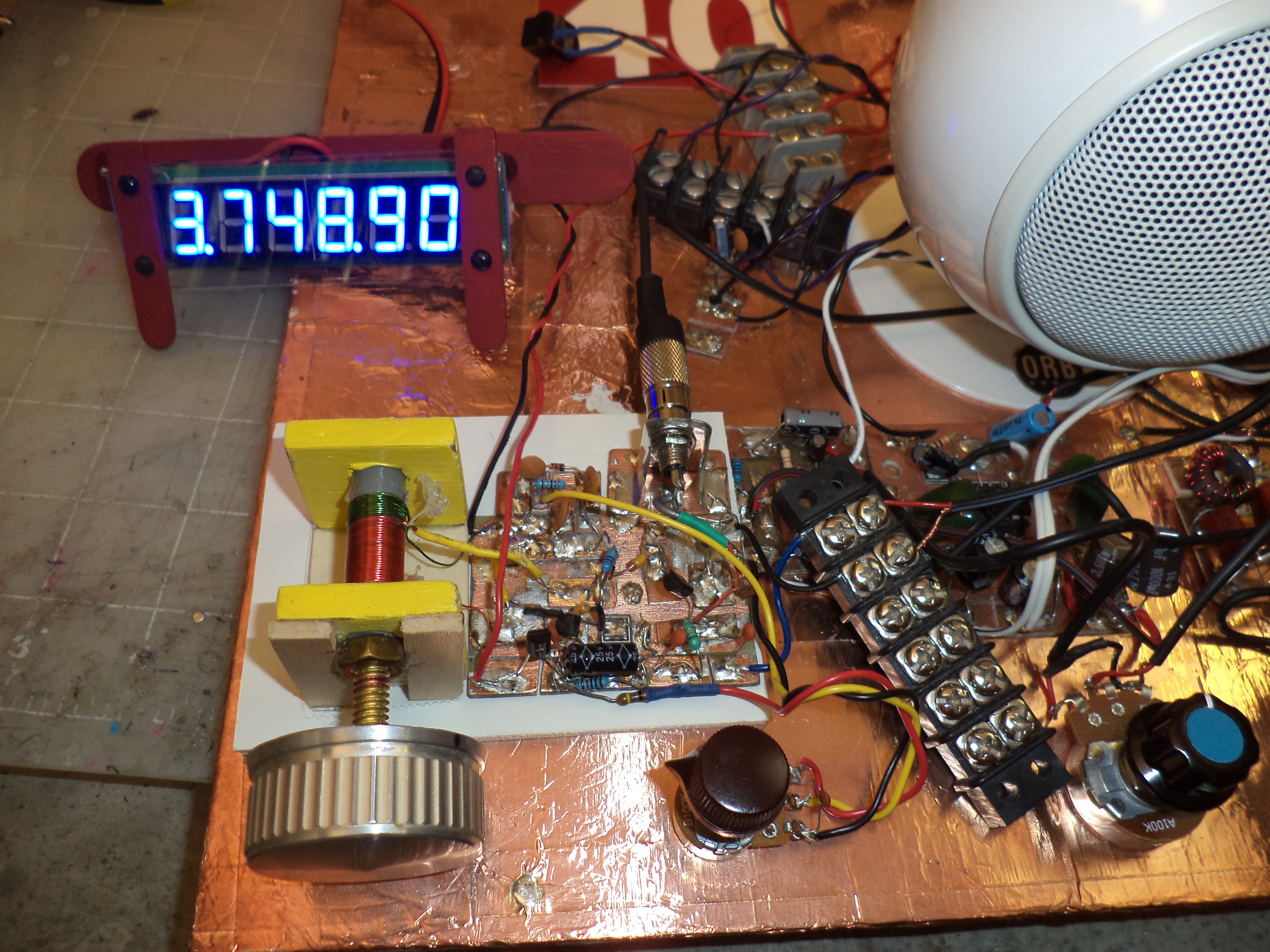
Net frequency of 7251, so using a BFO setting of 10,999.900, I simply set
the PTO to 3,748.90 on the 6-digit 10 Hz resolution counter I normally use (see third
photo).
7. I am currently using my Daylight Again PTO on a daily basis with
an NE602 receiver, and I am thinking of adding a locknut to the bolt
so it does not wiggle when I jostle or move the radio, essentially giving me
a crystal replacement oscillator that I can use for any single 40M
frequency. To date I have been able to listen for hours at a time indoors
without even any touch-up of the varactor fine tuning.
8. Also, if continuous frequency readout is desired without building a noise filter
circuit board, a separate power supply for the counter is a solution.
For portable operation I use Lithium Polymer radio control model airplane
batteries which are light, small, and cheap, so one 12V 2000 mAH battery
for the transceiver (allows a half hour of transmitting at 15 watts)
and a much smaller 12V 350 mAH battery with a series resistor to
reduce the current and brightness of the counter has worked well for me.
73,
Walter
KA4KXX
Orlando, FL
Tuesday, September 1, 2009
A Good Old VFO (by Rick, KK7B)
 Here is another really great message from Rick, KK7B, sent to the emrfd yahoo group:
[emrfd] A Good Old VFO
Saturday, August 22, 2009 10:29 PM
From:
Rick
To:
emrfd@yahoogroups.com
For several critical receiver applications in my lab I've used old Collins PTOs converted to solid state (I just replace the triode in the classic Hartley circuit with a J310 and run the circuit from a 9 volt regulator). I have half a dozen of them in dedicated propagation study receivers, and one SSB exciter I occasionally use on UHF. The other day I was changing something else in one of my receivers and connected the solid-state PTO to the frequency counter on my bench. The PTO was set to 3.100000 MHz. From a cold start (it hadn't been turned on for years) it drifted three Hz over the first ten minutes, and then a total of 10 Hz over the next few hours. When I calibrated one of my 144 MHz propagation study receivers 25 years ago, total frequency drift was <18Hz/hour. I expect most of that was aging of the overtone crystal oscillator in the premix circuit.
Old Collins PTOs are common (someone at Dayton this year had a box of unknown ones in decent shape for $10 each, and there are R390 PTOs in the current Fair Radio flyer). I've never had one fail, tuning resolution is infinite, phase noise is low, digital noise is zero, and once I build one into a receiver, that part of the project is done--no improvements, software upgrades, needed.
My research receivers are connected to a baseband Fourier analyzer (yes...even 25 years ago). The finest resolution I've used for serious experiments is 10 milliHertz, but more often I use 1 Hz resolution, with 1024 channels in the output spectrum. I often average spectra for more than a minute, so frequency drift needs to be less than 1 Hz per minute. The solid-state Collins PTO is much more stable than needed even for those critical experiments.
This is not a fluke. Every Collins PTO I've converted to solid state using a U310 or J310 has had similar performance.
Sometimes it is useful to remember that the major benefit of digital frequency synthesis is that it is quick, cheap, and frequency agile. No commercial manufacturer could afford to build a transceiver with a Collins Mil-Spec PTO in it these days. But for an amateur with mechanical skills or access to surplus hardware who needs just one good oscillator, the venerable Hartley with a temperature compensated tuned circuit and a JFET can provide outstanding performance.
In music, art, architecture, automobiles, motorcycles. .. there are recognized "golden eras" where some combination of factors resulted in technical hardware that is widely recognized as being superior to what is being produced today. Often the difference is directly related to the amount of skilled labor needed during production. As technical hobbyists, we automatically assume that new is better, but as experimenters, we should be open to the idea that sometimes the technology, ideas, and block diagrams of an earlier era are superior to the cost-driven disposable technology coming off fully automatic assembly lines in some out-of-the-way place with inexpensive labor and attractive business tax codes.
The idea that old technology designed decades ago by retired guys might be better than new technology is a radical concept in electronics. But NASA is using a brand new, hand built, Traveling Wave vacuum tube in the current Moon exploration mission. After 100 years of radio experiments- -it is fun to look back and find old technology that might actually work better than some of the new things we've been inventing recently.
Best Regards,
Rick KK7B
Here is another really great message from Rick, KK7B, sent to the emrfd yahoo group:
[emrfd] A Good Old VFO
Saturday, August 22, 2009 10:29 PM
From:
Rick
To:
emrfd@yahoogroups.com
For several critical receiver applications in my lab I've used old Collins PTOs converted to solid state (I just replace the triode in the classic Hartley circuit with a J310 and run the circuit from a 9 volt regulator). I have half a dozen of them in dedicated propagation study receivers, and one SSB exciter I occasionally use on UHF. The other day I was changing something else in one of my receivers and connected the solid-state PTO to the frequency counter on my bench. The PTO was set to 3.100000 MHz. From a cold start (it hadn't been turned on for years) it drifted three Hz over the first ten minutes, and then a total of 10 Hz over the next few hours. When I calibrated one of my 144 MHz propagation study receivers 25 years ago, total frequency drift was <18Hz/hour. I expect most of that was aging of the overtone crystal oscillator in the premix circuit.
Old Collins PTOs are common (someone at Dayton this year had a box of unknown ones in decent shape for $10 each, and there are R390 PTOs in the current Fair Radio flyer). I've never had one fail, tuning resolution is infinite, phase noise is low, digital noise is zero, and once I build one into a receiver, that part of the project is done--no improvements, software upgrades, needed.
My research receivers are connected to a baseband Fourier analyzer (yes...even 25 years ago). The finest resolution I've used for serious experiments is 10 milliHertz, but more often I use 1 Hz resolution, with 1024 channels in the output spectrum. I often average spectra for more than a minute, so frequency drift needs to be less than 1 Hz per minute. The solid-state Collins PTO is much more stable than needed even for those critical experiments.
This is not a fluke. Every Collins PTO I've converted to solid state using a U310 or J310 has had similar performance.
Sometimes it is useful to remember that the major benefit of digital frequency synthesis is that it is quick, cheap, and frequency agile. No commercial manufacturer could afford to build a transceiver with a Collins Mil-Spec PTO in it these days. But for an amateur with mechanical skills or access to surplus hardware who needs just one good oscillator, the venerable Hartley with a temperature compensated tuned circuit and a JFET can provide outstanding performance.
In music, art, architecture, automobiles, motorcycles. .. there are recognized "golden eras" where some combination of factors resulted in technical hardware that is widely recognized as being superior to what is being produced today. Often the difference is directly related to the amount of skilled labor needed during production. As technical hobbyists, we automatically assume that new is better, but as experimenters, we should be open to the idea that sometimes the technology, ideas, and block diagrams of an earlier era are superior to the cost-driven disposable technology coming off fully automatic assembly lines in some out-of-the-way place with inexpensive labor and attractive business tax codes.
The idea that old technology designed decades ago by retired guys might be better than new technology is a radical concept in electronics. But NASA is using a brand new, hand built, Traveling Wave vacuum tube in the current Moon exploration mission. After 100 years of radio experiments- -it is fun to look back and find old technology that might actually work better than some of the new things we've been inventing recently.
Best Regards,
Rick KK7B
Subscribe to:
Posts (Atom)