Podcasting since August 2005! Listen to our latest podcast here:

Podcasting since August 2005! Listen to Latest SolderSmoke

Showing posts with label Armstrong -E. Howard. Show all posts

Monday, July 27, 2026

Understanding Super Regeneration (Good luck!)

Edwin Armstrong presenting the superregenerative receiver at the June 28, 1922 meeting of the Radio Club of America in Havemeyer Hall, Columbia University, New York. His prototype 3-tube receiver was as sensitive as conventional receivers with 9 tubes.

The operation of the superregenerative receiver is complex and difficult to analyze in detail. As noted by Thomas H. Lee, it "has never been understood by more than a handful of people at a given time."[22]

https://en.wikipedia.org/wiki/Superregenerative_receiver

-------------------------------------------

This is from Gemini AI: 

WHAT IS THE BENEFIT OF SUPER-REGENERATION? 

When operating on the 2-meter band, switching from a standard regenerative detector to a super-regenerative detector yields a massive jump in single-stage receiver gain—typically an additional 40 to 60 dB -- a voltage amplification factor of 100 to 1,000 times greater.

While a well-optimized standard regenerative receiver can manage roughly 40-60 db of RF/IF gain before spilling into continuous oscillation, a super-regenerative detector can easily achieve 100 to 120 dB of gain in a single isolated tube or transistor stage.

Here is why that delta is so profound, especially at VHF:

The Mechanics of the Gain Boost

  • Regeneration (The Knife Edge): A standard regenerative receiver relies on positive feedback adjusted to sit just below the point of self-oscillation. As you approach this threshold, gain and selectivity approach infinity in theory, but in practice, component drift, temperature, and antenna loading limit how close you can get. At 144 MHz staying on this knife-edge is notoriously difficult.

  • Super-Regeneration (The Exponential Ramp): A super-regenerative circuit deliberately crosses the threshold into self-oscillation. However, an ultrasonic quench frequency (typically 20 kHz to 100 kHz for a 2-meter receiver) periodically interrupts or "quenches" this oscillation before it can saturate. Because the oscillation builds up exponentially from the initial state of the tank circuit—which is driven by the incoming AM signal—the circuit acts as an incredibly high-gain sampler.

Practical Implications on 2 Meters

  • Sensitivity: Because of that extra 40 to 60 dB of gain, a super-regen can easily pull a microvolt-level AM signal out of the noise floor, whereas a standard regen at VHF would require an external RF amplifier stage to match that sensitivity.

  • Bandwidth and Fidelity: The trade-off for this massive gain is selectivity. Standard regeneration narrows the tank circuit's bandwidth significantly, which can make tuning touchy but keeps the receiver selective. Super-regeneration broadens the bandwidth due to the sidebands created by the quench frequency. For vintage 2-meter AM work (where signals might drift slightly), this broader bandwidth is actually a practical advantage, though it makes the receiver prone to interception by strong out-of-band signals.

  • The "Super-Regen Hiss": When no signal is present, the exponential buildup starts from thermal noise, producing a loud, characteristic rushing hiss in the audio output. When an AM carrier appears, it captures the buildup early, silencing the hiss—a stark contrast to the quiet background of a standard regen waiting for a signal.

HOW DOES SUPER-REGENERATION REALLY WORK? 

 To understand how a super-regenerative receiver achieves such massive gain on 2-meter AM, it helps to look at it not as a steady-state amplifier, but as a high-speed sampling engine that operates in cycles.

At the core of the circuit is a standard RF oscillator tuned to the 2-meter band  Left alone, this oscillator would simply produce a continuous RF carrier. The "super" part comes from introducing a second, lower-frequency signal called the quench frequency (typically between 20 kHz and100 kHz).

Here is the step-by-step breakdown of exactly what happens during a single quench cycle:

1. The Quench Cycle (The Reset)

The quench oscillator constantly varies the bias of the 2-meter detector stage, swinging it back and forth between two states: sub-critical (where it cannot oscillate) and super-critical (where it desperately wants to oscillate).

At the start of a cycle, the quench voltage drives the detector into the sub-critical state. Any previous oscillations are completely wiped out. The circuit is wiped clean and made ready to sample the antenna.

2. The Exponential Buildup

As the quench voltage swings, the detector enters the super-critical state. RF energy begins to build up in the 144 MHz tank circuit. Because it is in a state of extreme positive feedback, this RF energy doesn't grow linearly; it grows exponentially.

However, an oscillator cannot start growing from absolute zero. It needs a "seed" to kick off the oscillation. This seed is a combination of two things:

  • General thermal noise in the circuit.

  • The incoming 2-meter AM radio signal from the antenna.

3. Sampling the AM Signal

If a weak AM signal is present on the antenna, its voltage combines with the background noise. Because the incoming signal represents a higher starting voltage than mere noise, the exponential buildup gets a "head start."

  • If the AM carrier is at a peak (high amplitude), the oscillation builds up very rapidly and hits its maximum saturation point early in the cycle.

  • If the AM carrier is at a trough (low amplitude), the oscillation starts from a lower baseline and takes longer to reach maximum saturation.

4. Direct Current (DC) Extraction

Because the RF oscillations reach saturation faster or slower depending on the strength of the incoming signal, the total energy or average current consumed by the detector tube or transistor during that cycle changes.

  • Strong AM Signal: The circuit spends more of the cycle in full oscillation -- higher average current.

  • Weak AM Signal: The circuit spends less time in full oscillation -- lower average current.

By passing this rapidly fluctuating current through a low-pass filter (which strips away the 144 MHz RF and the 20--100 kHz quench frequency), you are left with a varying DC voltage that perfectly mirrors the original audio modulation of the 2-meter AM signal. This is routed directly to an audio amplifier and your speaker.

Why It Sounds the Way It Does

This sampling process happens tens of thousands of times per second—well above the range of human hearing.

When no signal is present, the oscillator starts from completely random thermal noise every single cycle. Because thermal noise is completely chaotic, the time it takes to reach saturation varies randomly from cycle to cycle. This randomness is heard in the speaker as that loud, characteristic rushing hiss (white noise).

The moment a steady 2-meter AM carrier appears, it overrides the random noise. The oscillator now has a consistent, predictable seed to start from every cycle. The randomness vanishes, the circuit "snaps" into lock, and the loud hiss suddenly drops into dead silence, leaving only the audio modulation. 

IF IT IS SO MUCH BETTER, WHEY DON'T WE USE SUPER-REGENERATION ON HF? 

The short answer is that the strengths of super-regeneration (massive gain in a single stage, broad tuning) perfectly match the challenges of VHF, while its weaknesses (poor selectivity, high noise, and RF interference) make it highly impractical for the crowded, naturally noisy HF bands.

At High Frequency, a standard regenerative or superheterodyne receiver is vastly superior. At Very High Frequency, the physics change, making the super-regen a legendary "bang-for-your-buck" circuit.

Here is a breakdown of why this divide exists:

1. The Selectivity Problem (Bandwidth)

A super-regenerative detector works by constantly quenching and restarting an oscillator. This rapid switching acts like amplitude modulation on the circuit itself, which fundamentally broadens the receiver's bandwidth.

  • At VHF (e.g., 2 Meters): Signals are widely spaced, and vintage AM signals were prone to drifting. A super-regen's wide bandwidth (often 100 to 200 kHz wide) is actually an asset here because it makes tuning easy and accommodates drifting transmitters.

  • At HF (e.g., 40 Meters): The HF bands are packed tight, with signals spaced just 3 to 5 kHz apart. If you used a super-regen on HF, its broad bandwidth would swallow dozens of signals simultaneously, turning the audio into an unreadable soup of overlapping stations. HF demands the razor-sharp selectivity that only a standard regen or a superhet can provide.

2. The External Noise Floor vs. Circuit Gain

The primary reason you need a high-gain receiver changes depending on where you are in the spectrum.

  • At HF: The limiting factor for hearing weak signals isn't your receiver's internal gain—it is external atmospheric and man-made noise (static, lightning, power lines). Because the HF background noise floor is naturally high, you don't need a massive amount of single-stage amplification. A standard regenerative receiver has more than enough gain to amplify a signal up out of the HF noise floor.

  • At VHF: Cosmic and atmospheric noise drop off sharply at VHF. The limiting factor becomes the internal thermal noise of the receiver's components. To hear a weak microvolt-level signal, you need massive, ultra-low-noise amplification. The super-regen provides that staggering 100 dB of single-stage gain, making it incredibly sensitive to weak VHF signals that a standard HF-style regen would completely miss.

3. The Quench Frequency Ratio

For a super-regenerative detector to work properly, the quench frequency must be significantly lower than the operating RF frequency, but significantly higher than the highest audio frequency 3 kHz for voice).

Ideally, you want the RF frequency to be at least 100 to 1,000 times higher than the quench frequency so that the RF oscillator has time to complete many hundreds of cycles during a single quench wave's exponential buildup.

  • At VHF: A quench frequency of 50 kHz fits perfectly. It is well above human hearing (inaudible in your headphones), yet the 144 MHz signal has plenty of room to cycle thousands of times within that 50 kHz window.

  • At lower HF (3.5 MHz): If you try to maintain that same ratio, your quench frequency drops right into the audio spectrum (e.g., 5 to10 kHz). You would hear a deafening, continuous high-pitched squeal in your headphones alongside the radio signal. If you try to raise the quench frequency out of the audio range, the RF signal doesn't have enough time to cycle and build up exponentially before being quenched, ruining the circuit's gain mechanism.

4. Severe RF Radiation (The "Mini-Transmitter")

Because a super-regen is literally a high-power oscillator being driven into heavy saturation tens of thousands of times per second, it acts as a small spark-gap transmitter. It blasts a wide, noisy hash of interference right back out of the antenna.

  • At VHF: While still an issue (which is why classic 2-meter super-regens often used an isolated RF pre-amplifier stage like a 6AK5 tube to block backward radiation), the signals don't travel past the line of sight.

  • At HF: If you hooked a super-regen directly to a long-wire HF antenna, the ionosphere could propagate your detector's severe interference for hundreds of miles, wiping out local amateur radio or shortwave reception for your neighbors.

Monday, January 3, 2022

1BCG -- The 100th Anniversary of the Trans-Atlantic Test


Thanks to the Antique Wireless Association for this really wonderful video, and for their involvement in the 100th anniversary event.  Special thanks to Ed K2MP. 

On December 11, 2021, the 1BCG team in Connecticut had some technical difficulties.  As we all know, that is part of being a radio amateur. Details of the problems are presented here: 

http://1bcg.org/1BCG/the-special-event-transmitter/

Phil W1PJE managed to hear and record some of the 2021 transmission (Thanks Phil).  Listen here: 

https://drive.google.com/file/d/1uPvD9Qh-VJTnyDzOPPSrYfbksks8sQsx/view?usp=sharing

Phil also sent this spectrogram of the signal. 


Good thing Paul Godley ran into Harold Beverage on the ship going over. 

And imagine me complaining about having to step out into the carport to adjust my antenna -- Godley had to trek one mile THROUGH SEA-WEED to adjust his.  Respect.   

Saturday, December 18, 2021

On 17 meter CW from Santo Domingo with a uBITX


We are up on the 12th floor of a building in Santo Domingo. I brought my uBITX and managed to check in as baggage a 16-foot crappie fishing pole. I figured I needed to get the 1/2 wave antenna away from the building -- last time I was here I was unable to make any contacts from this location with the antenna stretched along the balcony. Last time I was QRP with an SST transceiver. 

The fishing pole worked well, but I operated with fear that it would fall or that the neighbors would complain). Today I got on 17 CW with the uBITX (more power than the SST), put it on 17 CW and promptly worked W4A, a special events station commemorating E. Howard Armstrong.  Turns out that today is Armstrong's birthday.  TRGHS.  

On the Reverse Beacon Network my CQs were heard by KO7SS in Arizona (very cool skimmer station at 8100 feet!) and by W2NAF (interesting operations in Antarctica, Svalbard and Virginia Tech). 


Wednesday, October 20, 2021

Super-Regeneration is Super-Strange


Farhan VU2ESE is largely responsible for this.  He has recently been talking about VHF.  (More about this in due course.).  This started me thinking about my failed effort in London to get on 2 meter AM.   My plan was to use the transmit portion of this HW-30 (above) with a 2-to-10 downconverter and my trusty Drake 2-B for receive.  

Tony G4WIF also bears some responsibility:  When I expressed interest in Farhan's VHF work, Tony sent me two articles from SPRAT.  Both of them were about super-regenerative receivers.  

Farhan's comments caused me to pull the HW-30 out of storage.  I started poking around the transmitter.  But then I noticed something:  On receive, the AF amplifier was obviously working.  Then, when I tuned through the 2 meter band, the rest of the receiver seemed to be working too.  I fired up the HP-8640B sig gen on 2 meters and turned on the AM modulation.  Indeed, the old receiver was inhaling!  

This launched me into an effort to understand how super-regenerative receivers work.  There are a lot of really weak explanations out there. You get the distinct impression that the person explaining the circuit does not understand it himself.  This makes explaining it very difficult.  I am not the only one to notice this phenomenon:  Mike WU2D commented on this in one of his excellent super-regen videos.  This one:  


Mike very kindly said the operation of this circuit seems like "magic."  I was thinking more in terms of Voodoo.  

Howard Armstrong discovered super-regeneration years after he invented plain old regeneration.  The new discovery came around 1921.

It looks like VHF guru Frank Jones had very early misgivings about super-regeneration.  In his 1934 classic 5 Meter Radio Telephony, Jones seems unenthusiastic about the circuit and about our ability to understand it:  "To explain, simply, exactly how this form of detection takes place is not a simple matter, but some of its characteristics are easy to visualize."  In this book, Jones goes on to predict that super-regens will be superseded (!) by superhets.  Indeed, in his 1961 book VHF for the Radio Amateur there are no super-regen circuits; all the receive systems are down-converters to HF receivers. 

Still, with that HW-30 hissing away right next to me, I feel I need to understand how the super-regen works.  I'm not there yet, but I'm trying.  Here are some good resources: 

A good article from Wireless World 1946:  

A student's write up of his effort to understand: 

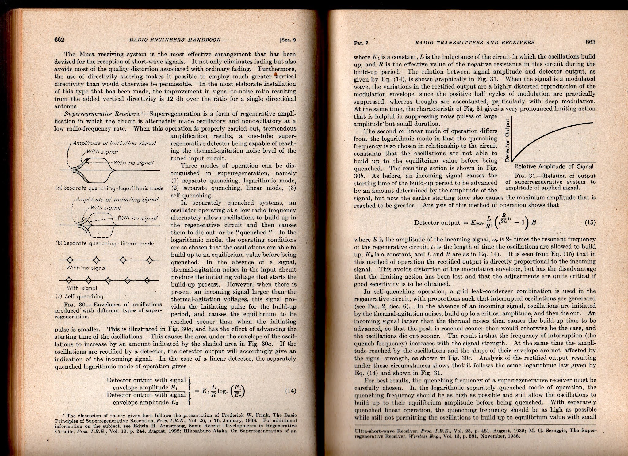
But the best so far (for me) is from Frederick Terman (one of the founders of Silicon Valley) in  his 1943 classic Radio Engineer's Handbook.  Click on the images for a clearer view. 


I will definitely try to get the HW-30's 5 watt AM transmitter going.  I am not so sure I'll do anything with the receiver.  I think this is a matter of picking your battles and "finding joy."   I didn't find joy in FT-8, so I stopped working with it.  Same with my HA-600A, DX-40 Novice rig.  Same with CW in general.  And the same with SDR.  I suspect that super-regen receivers may also fall into this category.  I mean, let's face it, if you are not fond of ordinary regens, is there any real chance that you will like SUPER-regens?  Even Frank Jones seems to have disliked them.  And there is a reason Howard Armstrong moved on to superhets -- they are better! But still, that receiver is hissing away at me...  Stay tuned. 

Friday, September 3, 2021

1BCG -- 1921 Transatlantic Test and the Upcoming 100th Anniversary


In December 2021 we will reach the 100th Anniversary of the famous Transatlantic Test that marked the first crossing of the Atlantic by radio amateurs.  The video above provides a really excellent description of the momentous event. A few things struck me: 

-- Even then they struggled with amplifiers that wanted to oscillate. 

-- Armstrong should have gotten more credit for the transmitter design.  After all, it was his regenerative system that gave rise to the kind of oscillators that allowed for CW (vice spark) and that formed the basis of the MOPA transmitter that these fellows used. 

-- The info on the Superhet receiver used by Paul Godley in Scotland was really interesting:  It used   "resistance-coupled amplifiers without transformers," similar to what we have today in Farhan's BITX transceivers. 

-- Wow, Harold Beverage himself! And his antenna was used at the Scotland receiving station. 

-- "It was a miracle that no one got mixed up with the high voltage."  Indeed.  

The Antique Wireless Association has built a replica of the 1921 transmitter.  The video below shows it being tested. 
 

The 1BCG website announces that: 

On December 11, 2021 the American Radio Relay League, The Radio Club of America and the Antique Wireless Association will recreate these historic transmissions on 160 meters near the same location that was used in 1921, using a replica transmitter constructed by volunteers at the Antique Wireless Association. This special event is your opportunity to relive a historic moment in amateur radio history.

The operating schedule and frequency for the 1BCG Transatlantic Tests Special Event has not been established.

Additional details will be posted here when they are available.


http://1bcg.org/1BCG/

Wednesday, August 25, 2021

Video: E. Howard Armstrong and Early Radio


This is a really wonderful video. It might seem slow to those accustomed to faster-paced YouTube videos, but the information content is very high -- it contains a lot of pictures I hadn't seen before and audio of Howard Armstrong.  

I never knew that the name of the radio company Zenith was derived from the early callsign "9ZN." 

As a Northern Virginian, I like the reference to NAA Arlington.  

I used to live near Yonkers, N.Y.  I remember Warburton Ave.  What a fine shack young Howard had up in that cupola attic.  

The photo of Armstrong's breadboard was very nice.  My Mythbuster is in good company.

QRPers will get a kick out of the newspaper headline "New Radio Marvel Revealed!"  (They cut the power out from 20kW to 5 watts!) 

Thanks again to Dave Bamford W2DAB for sending me the book about Armstrong, "Man of High Fidelity" by Lawrence Lessing.  

Finally, I remember talking to Bruce Kelley W2ICE at hamfests.   He was a great radio amateur: 

Be sure to check out the Antique Wireless Museum's YouTube Channel.  Lots of good stuff there: 

We have the famous photo of Major Armstrong,
 but this is the first one I've seen of a slightly younger Captain E. Howard Armstrong. 


Thursday, June 3, 2021

Remastered! The Secret Life of Radio -- With Updated Comments from Tim Hunkin


Thanks to Stephen 2E0FXZ for alerting us to this important video. 
We first posted about the original many years ago.  We were delighted to learn that they have remastered the video and added 10 minutes of retrospective commentary from Tim Hunkin.  

Here are some of my reactions after watching the updated version:
-- The Marconi videos were amazing.   I actually met Elettra at a diplomatic reception in Rome.  
-- I was pleased to learn that Marconi was trying to "call up" Mars.  FB OM. 
-- My son Billy and I sat in that same Royal Institution auditorium where, 100 years before, Oliver Lodge had demonstrated spark gap technology. 
-- Tim's comment on the connection to supernatural beliefs was right on the mark.  We found out that the house we lived in in London was a center for occult beliefs and practices. 
-- Those square lantern batteries brought back fond childhood memories. My first power supplies.
-- The Rexophone -- used by Rex. 
-- Very cool of Tim to homebrew a coherer.  Extra credit for that.
-- One of the capacitors looks familiar.  EF Johnson? 
-- I agree with Tim -- crystal radios are a must-build for true radio hams.  And do it with galena and a cats whisker. 
-- Finally, the RCA ad introduces a term we might want to surreptitiously enter into the Enhanced SSB lexicon:  That "Golden Throat" sound.   


Monday, November 25, 2019

SolderSmoke Podcast #215 Regen Madness, KWM-4, Paesano, Mailbag

Latest N2CQR version of N0WVA's Regen
SolderSmoke Podcast #215 is available. 

25 November 2019

http://soldersmoke.com/soldersmoke215.mp3

Happy Thanksgiving! 
Transit of Mercury
Book Reviews 

Bill's Minimalist Adventures:
-- 15 Contacts with the ET-2 
-- Ethical issues:  Is spotting yourself OK?  OK to use TWO FETs? 
-- Using Reverse Beacon Network
-- How to keep receiver on the right frequency
-- N0WVA's receiver sounded better, so I built a second N0WVA receiver
-- Regens reach back to Edwin Howard Armstrong's 1912-1923 breakthrough
-- Regens are fun, but they are not good projects for new builders. 

-- Pull out those Michigan Mighty Mites and listen for yourself via on-line SDR receivers.

Pete's Projects: 
"WHEN YOU KNOW STUFF YOU CAN DO STUFF!"
-- Left Coast SSB -- "The Paesano" -- To be featured in December 2019 SPRAT. 
-- Pete's KWM-4 on The Collins Collectors Net
-- Pete builds an N0WVA regen -- just in time for Sweepstakes CW Saturday! 
-- Arduino IDE Library trouble
-- uBITX 6.0? Fake News? 

No more BITX40 Modules.  Long Live BITX40 HOMEBREW! 

BITX-101.   Intriguing but on second thought, no.   

MAILBAG

Steve Silverman:  Lexicon:  "Audible Modes." 
Felipe CU2BD   Old buddy from the Azores
Michael Rainey AA1TJ:  Come back Mike!  The ionosphere needs you! 
Jack Welch  AI4SV is in 5G land  (Cyprus, not the cell phone thing). 
Walter AC4IM is at the San Vito Solar Observatory in Italy.  DO SOMETHING WALTER! 
Kostas SV3ORA has an amazing homebrew web site.  Thanks Kostas! 
Mike KC6SAX -- How to deal with the frustration of HB projects that don't work. 
Paul KL7FLR -- Pete is 7 Hz high. 
Keith W3ISZ  sent his photo of the Transit of Mercury.  

PLEASE USE THE AMAZON SEARCH BOX ON THE SOLDERSMOKE BLOG PAGE WHEN DOING YOUR CHRISTMAS SHOPPING. 

PLEASE SUBSCRIBE TO THE SOLDERSMOKE CHANNEL ON YOUTUBE. 


N2CQR's ET-2 with callsign Tattoos 

Thursday, May 9, 2019

Book Review: "Man of High Fidelity: Edwin Howard Armstrong" (Free Download)

Dave W2DAB sent me this wonderful book.  He picked up a copy at a recent Columbia University lecture on E. Howard Armstrong.  Written by the notable science writer Lawrence Lessing, the book was first published in 1956.  The paperback copy that Dave sent me came out in 1969; while 50 years old, my copy is in remarkably good shape. 

I really liked the book.  The author captures the technical achievements of  Armstrong, while also describing vividly the world in which Armstrong lived.  Being from the area, I especially liked Lessing's description of New York City and the Hudson Valley in the early years of the 20th century. This was the world of my grandparents; Lessing's book helped me understand it better. 

For the radio amateur, I think the most gripping part of the book is the way Lessing describes  the excitement of early radio.  Armstrong was a true enthusiast for the new technology, and he was -- even as a teenager -- at the cutting edge.  He was constantly striving to improve the technology, especially the receivers.  Like us, he often became obsessed with his radio work, often forgoing sleep and missing family meals as he toiled away in his workshop. Lessing tells us of Armstrong's astonishment and joy, when, upon inventing the regenerative receiver, he was suddenly able to clearly receive signals from distant stations that previously had been barely discernible.  Realize that when he was doing that, he was the only person on the planet who was doing it.  He was the inventor. He was the first. 

Lessing gives us a lot of great information about Armstrong's work as an officer in the U.S. Army Signal Corps in Paris during World War I.  We learn more about how his desire to be able to detect noise from the electrical systems of enemy airplanes led him to the invention of our beloved superhet receivers.   But my favorite Armstrong in WWI story involves his visit to the radio shack of the ship that was carrying him to the war.   In the radio shack he found a conventional station.  But he asked the operator if he happened to have one of the then new audion tubes.  On the spot, Armstrong took the tube and rigged up a regenerative receiver.  He and the ship's radioman then delighted in hearing stations that had never before been audible.   Amazing.     

I was less interested in the sad tale of Armstrong's legal patent battles, so I kind of skimmed through that.  I'm also not much of an FM guy, so I'll save those portions of the book for a later date.  

I think this is an important book about a significant part of radio history.  It is well written.  It gets almost all of the technical details right (but sorry Mr. Lessing,  radio waves are not composed of electrons).  The book deserves a place on the shelf of all radio history libraries.   If you can't get a print copy, an online version can be downloaded here: 

 https://archive.org/details/in.ernet.dli.2015.189098

Thanks again to Dave W2DAB.   

Saturday, May 4, 2019

SDR vs. HDR - Is the Superhet Dead?


Pete N6QW had this very interesting video about Software Defined Radio on his blog.  Thanks to G3WGV for putting this presentation together. 

It is very interesting, but -- for me -- it is also troubling.   I think something important is being missed in this discussion. You have to listen carefully, but if you do the thing being missed becomes apparent. 

Like many others, G3WGV asserts that very soon, 100 percent of commercial radios will be SDR.  Traditional superhet radios will be a thing of the past. 

OK, but I will make a parallel assertion:  Looking ahead, I think 100 percent of TRULY homebrewed rigs will be HDR.  

Of course, this really just comes down to how you define "homebrew."  I'm a traditionalist here.  I think of homebrewing as actually building -- from discrete components -- all the stages that send or receive radio signals.  By my definition, I don't think you can really "homebrew" an SDR radio.  Taking an ADC chip and connecting it to a computer running SDR software is not -- by my definition -- homebrew.  Even if you wrote the software yourself, writing code is not the same as wiring up all the stages that go into a superhet-style transceiver.    

There were a few lines in G3WGV's talk that seemed to confirm this difference:  The SDR radio is defined as a "server." Commercial manufacturers like SDR because they can use the same components that go into cell phones (exactly -- and people will soon have the same relationship with these "radios" that we have with their cell phones). 

I kind of grimaced when G3WGV described the two sets of users of SDR technology: the "early adopters" who are "technology enthusiasts",  and the "pragmatists" who don't care what's in the box -- they just want to talk on it.  I think "pragmatist" is a nice way of saying "appliance operator." Even the "early adopters" are pretty far from the world of traditional homebrew.  And for me that gets to the point that is being missed in all this -- this shift away from hardware is also a shift away from homebrew.   

But hey, this is a hobby.  To each is own!  Have it your way.  For myself, I plan to continue with the hardcore, radical fundamentalist, hardware-defined, discrete component, fully analog homebrew radio.  This morning I am attempting to stabilize a cap and coil VFO.  And I'm liking it.  As the world shifts to SDR, I look forward to the appearance on e-Bay of massive quantities of old forsaken HDR rigs.  We will buy them for pennies on the dollar and use the parts for new HDR Superhet rigs.  

Viva  E. Howard Armstrong!   Viva!   


Monday, January 28, 2019

The Secret Life of Machines -- Radio


We had this on fhe blog three years ago, but it is so good that it deserves a second posting. 
Thanks to our old friend Stephen Walters for reminding us of this gem.  There is so much soul in these old machines. Thanks Stephen. 

Wednesday, December 21, 2016

Monday, December 21, 2015

The Secret Life of Machines -- The Radio (Video)


Thanks to Rick N3FJZ for sending this to us.  In 25 minutes these fellows manage to capture and explain much of the "magic" of radio.  Great shots of Marconi, and of Hertz's first rig.  Amazing how they built their own spark transmitter and coherer receiver, launched a kite antenna and sent a signal across the harbor.  Great stuff.  Lots of history.   We've met Mr. Wells before -- he was "jailed for having the Knack!"

Friday, September 12, 2014

Schematic for "Off the Shelf" Regen


NOTE (May 2024) The eagle eye of Walter  KA4KXX spotted an error in this schematic.  The source resistor in the MPF-102 stage should be around 2200 ohms.  Thanks Walter! 

Tony, VE7JUL, wrote in asking for a schematic on the "Off the Shelf" regen.  Here you go Tony.  Nothing fancy or new here.  All the credit goes to Howard Armstrong, Charles Kitchin and Jay Rusgrove! 

Even though they seem much simpler than other receivers, I think regens are in fact more of a challenge than, say, a Direct Conversion receiver.  Be prepared to do a lot of fiddling around with the coil and the tuning and regen capacitors.  Think of that detector stage as a VFO, a VFO that you want to be able to smoothly take out of oscillation. 

Here's a tip on regen debugging:  Once you have it built, hang a high impedance 'scope probe off the drain of the FET and watch the scope/counter as you move the main tuning cap and the regen control.  This will give you a visible indication of where (on the regen control) the stage is going into oscillation.  A freq counter (I have one inside my Rigol 'scope) will let you know what frequency range you are operating on.  You may end up having to make adjustments to the coil, adding or taking away turns to get into the proper frequency range, or to the desired level of feedback.  Pay attention to the phasing of the coil turns.  You may also find yourself adding capacitance in series with the regen and main tuning controls (to reduce their tuning range) or adding capacitance in parallel with the main tuning cap (to lower the entire tuning range if necessary).  

Build it solid and strong!  It is, after all, an oscillator.  Be prepared to do a lot of "noodling"   


Hi Bill,
This receiver with just 4 transistors and no chips looks really interesting to me.  Do you have a schematic that you could either flip to me or point me to?  Getting my hands on some air variable caps may be a challenge, but I can 'noodle' something out on that.
Love the podcast, blog and really enjoyed the SolderSmoke book - thanks for your continuing efforts to share with the amateur radio community.
73/72
Tony
VE7JUL
the little red dot at Coquitlam, British Columbia on what used to be the Clustr map (but is now a Revolver map)


Our book: "SolderSmoke -- Global Adventures in Wireless Electronics" http://soldersmoke.com/book.htm Our coffee mugs, T-Shirts, bumper stickers: http://www.cafepress.com/SolderSmoke Our Book Store: http://astore.amazon.com/contracross-20

Thursday, November 11, 2010

Armstrong Memorial Transmissions

Here is the site for the Howard Armstrong 75th Anniversary of FM Transmissions:

http://www.wa2xmn.ar88.net/

Be sure to follow the links on that page to the Phasitron Transmitter page. Very nice workmanship.

Friday, January 22, 2010

Does Math Lead to Understanding?

In "SolderSmoke -- The Book" I describe the quest for deep understanding of the circuits that we build and use. There is some discussion in the book of the role of mathematics in this quest. A while back a reader e-mailed me on this subject. In the hope of stimulating a discussion, I'll present the key paragraph from that e-mail here (the author will, for now, remain anonymous):

I appreciate your quotes from Feynman, Asimov, etc. about not
really being able
to fully understand everything. As a math teacher
I can say that one of the
biggest misunderstandings about math
is that it "explains" the phenomena of
physics and engineering.
(Science and
math teachers are notorious for saying to a student
who has just asked a "why" question things like, "well the
math is
a little bit more complicated than what you can handle right now.
Wait until
you have had a year or so of calculus.") In reality it's
the exact opposite!
The math equations actually hide the answers.
They are very good at accurately
describing phenomena, or at
predicting what will happen next, but they can never
answer the
question of why one equation works and another does not. We
get very
comfortable with allowing the familiar math equations
to hide our inability to
really answer the "whys."

This really resonated with me. In my effort to get a better grasp of mixer theoy a lot of people seemed to be simply pointing me to the trig equations, and equating a knowledge of those equations with an understanding of how the mixer circuits really work.

Of course, I don't mean to be anti-math here, but I thought the e-mail on the limits of mathematics was very interesting.
In "Empire of the Air" Tom Lewis wrote, "At Columbia, Edwin Howard Armstrong developed another trait that displeased some of the staff and would annoy others later in life: his distrust of mathematical explanations for phenomena of the physical world. All too often he found his professors taking refuge in such abstractions when faced with a difficult and seemingly intractable conundrum... Time and again as an undergraduate at Columbia, Armstrong had refused to seek in mathematics a refuge from physical realities."

Monday, February 16, 2009

Armstrong's Regen (and lots more)

There it is. Howard Armstrong's regenerative receiver. Mike, KC7IT, led me to the wonderful website that has this picture, and much more. The site has all kinds of schematics and pictures and letters related to the work of radio pioneer Howard Armstrong. Check it out (you should probably take the tour by hitting the NEXT button on each page):
http://users.erols.com/oldradio/eha1.htm

I continue to work on my regen (part of the ET-1/FETer minimalist project). Jim, K9JM, says the raspy tone on CW signals is caused by FMing of the regen stage and prescribes a coil of higher Q. Thanks Jim.

Wednesday, January 28, 2009

My ET-1 / FETer (Transceiver Made with One FET)

Magnificent, don't you think? This is my version of the ET-1 or FETer. It is an HF transceiver using only one active device -- a single MPF-102 Field Effect Transistor. I didn't have a 4 pole Double Throw switch in the junkbox, but I did have a 4PDT relay, so I used the relay. So far I have only built the receiver. It is working nicely. I was listening to German and Polish stations on 80 meter CW this morning.

I had always wanted to build W2UW's ET-1... I've been reading in "Empire of the Air" the inspiring account of Armstrong's invention of the regen receiver... Then, along came SPRAT 137 and G3XBM's FETer. I could no longer resist. Solder was melted.

It is great fun to listen to 80 meters and realize that the only thing between you and the ether is one small FET (you can see mine standing proudly atop the relay!) . Its a lot like using a crystal receiver. That one FET is serving simultaneously as an RF amplifier, mixer and BFO!

On to the transmitter! Thanks to OM Armstrong, to Glen (W2UW), and to Roger (G3XBM).