Serving the worldwide community of radio-electronic homebrewers. Providing blog support to the SolderSmoke podcast: http://soldersmoke.com
Podcasting since 2005! Listen to our latest podcast here:
Podcasting since 2005! Listen to Latest SolderSmoke
Tuesday, May 30, 2017
The Transistor! 1953 Bell System Film -- Great Stuff!
Thermatron fans beware! There is some trash talking of tubes in this 1953 Bell film. But there is also a lot of recognition of the contribution made by our beloved valves. I especially liked the report on the historic 1915 phone transmissions from Arlington, Virginia. ( I drive past the transmitter site every work day). FIVE HUNDRED TUBES combined to send the human voice from Arlington to both the Eiffel Tower and to Pearl Harbor, Hawaii. FB OM! 59!
I was disappointed, however, that this film failed to recognize another momentous 1953 achievement in sold state electronics: In that year, 11 year-old Pete Juliano built his first solid state amplifier -- an audio amp using a CK722 transistor. Read about it here: http://soldersmoke.blogspot.com/2015/03/pete-juliano-homebrwing-with.html
The fact that Pete was homebrewing solid state circuits at the time that this film was made is a reminder of the vast experience that he has, and of how much technological progress we have made in such a short period of time.
Farhan gives me a Spectrum Analyzer and W2AEW Provides the Tutorial (Video)
At Dayton, Farhan very kindly bought me a Tektronix Spectrum Analyzer. (I joked during his visit that this device might help me stay in the good graces of the FCC.) This morning I decided to learn more about this device. I Googled "Tek 1401A" and was immediately directed to a YouTube tutorial. I was pleased to see that it was from our old friend Alan Wolke W2AEW. I knew that the Tek analyzer and I were in good hands. TRGHS. Alan expertly laid out the functions of the device. I am confident that I will soon be analyzing the spectrum of my homebrew rigs, and that they will all be found COMPLETELY FREE of spurious emissions.
Alan's tutorial is instructive for all those getting started with spectrum analyzers.
I need to find a manual and schematic for the 1410A.
Thanks Farhan. Thanks Alan. And three cheers for Beaverton, Oregon!
Monday, May 29, 2017
Indonesian BITX: Check out the BRITX
Pretty cool, don't you think?
Here is the Google translation of the "about" portion of OM Dian Kurniawan's blog:
Electronics is something very interesting. In it are stored many miracles of His creation. The almost limitless opportunities for creativity make electronics an art medium. Countless things are ultimately made easy and possible with electronics....
Feel free to start. Life starts from a cell. Let's keep working for a better life.
Salam.
It is obvious that OM Dian has THE KNACK and is a member of the International Brotherhood of Electronic Wizards. Does anyone know his callsign?
There is a lot of very cool stuff on his blog, including some mind-blowing applications of small, color displays. Check it all out:
Sunday, May 28, 2017
FDIM: W8SX Interviews Mike Bryce WB8VGE
Mike Bryce's many contributions to the radio art and QRP definitely puts him in the Homebrew Hero category. I have Mike's "Hotwater Handbook" (about the legendary HW-8) on my bookshelf. Our intrepid SolderSmoke media team (Bob W8SX) spoke to Mike at FDIM 17. His comments on the joy of a good troubleshoot, and on the pernicious, unfixable nature of many recently marketed appliance radios really resonated with me.
Mike has special expertise on Heathkit gear: https://www.theheathkitshop.com/index.html
Listen to the interview with Mike here:
KEEP THAT GREEN FLAME BURNING MIKE!
Saturday, May 27, 2017
FDIM: W8SX Interviews W8TEE on Facelifts for SSB Rigs
Our intrepid correspondent Bob Crane interviewed FDIM speaker Jack Purdum W8TEE. Jack made some very intriguing comments on his efforts to enhance the beloved BITX transceiver. CW! AGC! Speech processing! Woo hoo! We await more details on how to acquire the board that Jack describes.
Jack is a very accomplished guy who has made many contributions to the radio art, most recently on Arduino microcontroller projects: https://www.qrz.com/db/W8TEE
Listen to Bob's interview with Jack here:
http://soldersmoke.com/FDIM17W8TEE.mp3
Thanks Jack! Thanks Bob!
Here are is the manual, bill of materials, and schematic for Jack's board:
http://soldersmoke.com/W8TEEschematic.pdf
http://soldersmoke.com/W8TEEmanual.doc
http://soldersmoke.com/W8TEEbom.doc
Friday, May 26, 2017
Homebrew Peppermint BITX: KC1FSZ Goes Scratch-built and Sweeps a Filter
Congratulations to Bill on the award. Very well deserved!
I just watched the video that Bill made with Farhan and I really enjoyed it. As usual, lots of useful information there.
Farhan’s demo of the Sweeperino was particularly timely because this past weekend I was doing something very similar.
As I’ve mentioned to Bill before, I am working on a scratch-built BITX to accompany the Peppermint BITX-40 module rig that I’m running right now. I took Pete’s advice and started from the audio end. After building the audio amplifier, product detector, and first/last pair of IF amplifiers, I was able to connect the VFO where the BFO is supposed to go and enjoy a pretty reasonable direct conversion receiver. It works great!! My first working receiver.
So my next step was the crystal filter. I puzzled over all of the different articles, tried to follow the G3UUR method, sorted crystals, etc. and finally put the whole thing together. But all along I’ve had this doubt that I could have possibly followed all of the steps closely enough to achieve the precision needed for a 3.5 KC SSB filter - it just didn’t seem possible.
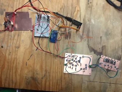
Last week I decided to try to “sweep” the filter. This was a multi-day undertaking in itself. I pieced together the microprocessor, an AD9850, a TIA amplifier, the RF power detector from the SSDRA book, and some software that generates the necessary frequency sweep and collects power readings. The picture of the test rig is included below. It’s not much to look at.
With low expectations (and wires that are too long), I ran a few seeps and then downloaded the data onto my computer for analysis. No fancy software here, I’m just using Excel. When I put the data into a line chart in Excel, what emerged from the jumble of seemingly random numbers was a thing of beauty: a 3.5 KC passband right below 12 MHz. It’s the next stage beyond the Joy of Oscillation: The Joy Of Selectivity!
It’s even showing about the right insertion loss. Note the setup is very primitive and noisy so the fact that I can’t measure anything below -8dB isn’t surprising, you can ignore that part.
But I’m starting to get the feeling that this might actually work. Onto the diode mixer …
73s,
Bruce KC1FSZ https://www.qrz.com/db/kc1fsz
Thursday, May 25, 2017
VU3XVR's BEAUTIFUL Morse Keys
Truly a thing of beauty. Farhan gave me one of these. They are crafted by VU3XVR. It is enough to turn a phone-guy like me back to CW. Thanks Farhan!
Here is VU3XVR's site:
http://vu3xvr.blogspot.com/p/morse-key.html
Wednesday, May 24, 2017
FDIM: Listen to Bob Crane Interview Hans Summers, G0UPL
Bob Crane, our intrepid correspondent at the 2017 Four Day in May event, caught up with Homebrew Hero Hans Summers G0UPL. Hans's amazing web sites have been the inspiration for many projects in my shacks. My favorite so far was his QRSS transmitter using an LED based multivibrator circuit to generate a shark fin pattern on grabber screens. That was fun. I am now really tempted to send one of Hans's WSPR transmitters into the stratosphere using party balloons.
Listen to the interview here:
http://soldersmoke.com/FDIM17G0UPL.mp3
Visit Hans's QRP-Labs here:
https://www.qrp-labs.com/
Thanks Bob! Thanks Hans!
Listen to the interview here:
http://soldersmoke.com/FDIM17G0UPL.mp3
Visit Hans's QRP-Labs here:
https://www.qrp-labs.com/
Thanks Bob! Thanks Hans!
Monday, May 22, 2017
Video: Farhan in the SolderSmoke Shack! BITX, JBOTS, McDonald Straw Sig Gen, uBITX, Sweperino and more!
Thanks again to Farhan for visiting us. It was great to see his reaction to my humble implementations of his great designs. I got him to sign my BITX17. This was really a fantastic day for me and for my family.
Sunday, May 21, 2017
Farhan Visits SolderSmoke Headquarters
Wow, today was an important day in the history of SolderSmoke. Our friend -- and newly minted member of the QRP Hall of Fame -- Ashhar Farhan VU2ESE came to see us. We had a great time. I showed him all the many devices that I built based on his designs.
We shot a video of the shack visit. I will post it to YouTube in a few days.
Thanks for coming to see us Farhan. And congratulations on the richly deserved Hall of Fame Induction.
Wednesday, May 17, 2017
Homebrew History is Made: Farhan @ W7ZOI
Thanks to Wes W7ZOI for sending me the link to his page describing the visit of our friend Farhan. I think this visit was a historic gathering of homebrew heroes and their groundbreaking rigs. Read all about it here: http://w7zoi.net/Farhan-visit.html
Please help me convince Farhan to visit SolderSmoke HQ before returning to India! Send him (or me) e-mails, texts, tweets, or just post messages of support below this post.
Tuesday, May 16, 2017
WA8WDQ's Automated Filter Scanner (and a tip from VK1VXG)
Bill, Pete,
Thought I'd share today's activities. Using Bill's excellent wire stripping technique, I was able to finish assembling my 7 MHz bandpass filter. At this point, I'd normally terminate the filter then hook up the signal generator and oscilloscope to manually scan/observe the filter's response. But today, I took a different tack. Using the AD9851/Arduino signal generator I built last year coupled with the W7ZOI AD8307 Power Meter I built this year, I wrote some additional Arduino code to scan a block of frequencies while using the Arduino's A/D to record a level at each scanned frequency, thus characterizing the filter's response. I also used a W7ZOI unidirectional TIA to boost the generator's output to within the full scale range of the A/D. This setup is similar to the popular PHSNA project that has gained attention over the last couple of years. The Arduino formats the data as CSV then feeds it into Numbers (the Mac Excel equivalent.) for plotting (see attached but please forgive the labels/legend on the plots as I didn't take the time to format them). Unfortunately, my Arduino UNO is low on RAM so I'm only able to save a max of 100 scanned frequencies. Even with the lack of resolution, as you can see, the output is definitely useable to get a sense of the filter shape and roll-off. I'm now motivated to write some plotting code so I can get a more real-time output in lieu of the spreadsheet. The output of the AD9851 seems pretty flat within several MHz as is the TIA, so the accuracy should be pretty good within moderately sized scan blocks. Adding additional external FLASH (or moving to a bigger Arduino like the Zero) will fix the low resolution. FYI - Arduino behavior when RAM is low can be very erratic! It started crashing when I got close to the max available :(.
If you haven't as yet, definitely check out the PHSNA project. They've added a boat load of features beyond just scanning filter response . . . and at a fraction of the cost of a spectrum analyzer with a tracking generator.
Brad WA8WDQ
Hi Bill,
I'm having trouble posting a comment in response to Brad, WA8WDQ's
automated Filter scanner project, and I'm hoping you wouldn't mind
passing this tip along. It might be of use to other readers too.
Recent versions of the Arduino software include a Serial Plotter feature
that lets you graph directly from your arduino. By making use of this
feature Brad wouldn't need to save data on the uno - just send it back
to the computer and graph in realtime. It is a little primitive, but
still usable. I believe the plot window is 500 datapoints wide.
There is a nice tutorial on how to use it here:
If you're in a hurry and can survive with a bit of inaccuracy in your
sweep measurement you can also get away with using a simple diode
detector RF probe. This is good enough for a "yep, that filter does
what I want" measurement, but not for measuring exact loss or 3db
bandwidth etc.
Hope that helps,
73s
Greg, VK1VXG
Tuesday, May 9, 2017
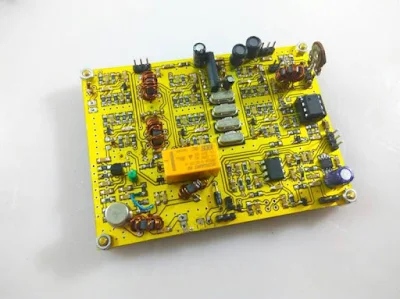
An NE602 SSB Design from China: The KN-Q7 by BA6BF
Allison KB1GMX alerted us to this rig. Pete and I had been discussing with her various designs for SSB transceivers. I recently completed an NE602 rig.
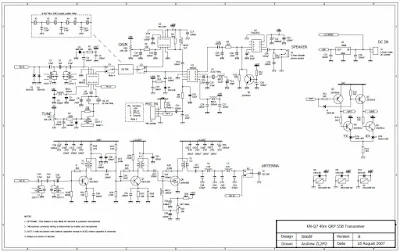
I really like the KN-Q7 (click on the picture above for a closer look). The T/R switching is much simpler than my use of three DPDT relays. It even seems simpler than the Epiphyte's switching of the BFO and VFO frequencies. I also like the analog VFO and BFOs inside the 602s, but I think Pete would use an Si5351. The AF amp muting circuit is kind of neat.
I questioned the need for the extra IF amp for the receiver. My rig just uses the two NE602s and an AF amp circuit from the BITX40 module (2N3904 and an LM386), and with this I can hear the band noise floor on 40. But Allison points out that different bandpass and crystal filter have different losses, so with these components some additional gain may have been necessary. YMMV.
Here is the kit manual:
Here is a video of VK2TPM putting his KN-Q7 on the air:
It is interesting that Peter notes a need for additional mic gain. Some of the NE602 rig designs run an electret mic right into the NE602 balanced modulator with no mic amp. For a few days I had my amplified D-104 mic running into the NE602 in this way. I too found that I was having to "loud talk" into the mic. I put an LM741 mic amp in there and it fixed the problem. I wonder if later versions of the KN-Q7 included a mic amp. I will check on this later.
Three cheers for designer Shi Ke, BA6BF!
Sunday, May 7, 2017
Still Photos and Slow-Motion Video from Shenandoah Rocket Launches
The above slow-motion video of launch #3 is pretty cool. You can very briefly see a bit of the yellow parachute deploying. The best video from this flight is at the end, as the rocket floats over the farm buildings and comes perilously close to landing on top of one of the silos. I put some snap shots at the end. Five other launch videos are available here: https://www.youtube.com/user/M0HBR/videos
SNAP SHOTS
Launch crew visible - N2CQR with hat, Billy to his left. Randy's son (next to Billy) launches the rocket!
Smoke trail back to the launch pad.
MECO! And you can see the smoke trail up to the rocket
The view across the Shenandoah Valley.
Skyline Drive runs along that ridgeline
Here is a hunk of flame-proof wadding ejected by the rocket.
We were afraid it would land on the silo. It was close.
GREAT BALLS OF FIRE! And a smoke trail.
Part of the deploying parachute is visible.
Subscribe to:
Comments (Atom)


