Podcasting since 2005! Listen to Latest SolderSmoke

Showing posts with label Polyakov--Vladimir. Show all posts

Thursday, August 11, 2022

What Coil for the Polyakov Input Circuit? How to calculate a coil value for resonance.


So,  what is the value for L1 and L2?   What coil should I use?  
Michael AG5VG had that question.  And so did I when I built this receiver.  See below for the process I used in answering this question. 

On Tuesday, August 9, 2022 at 10:53:32 PM EDT, Michael S  wrote:

Good Evening Bill,

My name is Michael and I really enjoy your podcast with Pete. I have also spoken with him in regards to the design of a 20M bandpass filter I made for a homebrew rig.  I am currently in the process of making a 20 meter DSB - SC type. Thank you for all the information that you speak and teach about during your podcast. I also enjoy the humor. It's great.

The Polyakov is a simple DC receiver and it amazes me and how the sound quality is. My question is, what is the turns on the toroid for the antenna primary side and the radio secondary and how did you figure out the turns because looking at the schematic it doesn't give that information that I can see. Also how you resonated it with the variable capacitor that looks like a 365pf air variable. 

Thank you for your time and keep up the great work on the podcast and the content on YouTube.

73s,
Michael
AG5VG

My response: 

Good questions Michael.   When I saw the SPRAT article I too was struck by the fact that it didn't give a value for the coil.  But DK2RS did have a large value variable capacitor... And he was billing this as a dual-band (80-40) rig.  So I figured he wanted that LC circuit to resonate as low as 3.5 MHZ and as high as 7.3 MHZ.  So, with a variable cap that goes up to 350 pf, what value L should I use?   I started by calculating the resonant frequency of the frequency mid-way point: 5.1 MHz.   I figured the variable cap should be around 162 pf at the mid-way point.  At this point I went to the on-line resonant frequency calculator: https://www.1728.org/resfreq.htm (a REALLY useful site!).   This site revealed I needed a coil of about 6 uH.  This put me in the ballpark.   But then -- with the site -- I tested it with the values of the variable cap I had on hand.  Mine was 23pf to 372 pf.  (you really need an LC meter to do this kind of thing). 

Again at the resonant freq calculation site:  23 pf and 6uH = 13.5 MHz           372 pf and 6 uH = 3.3688 MHz

This would have been OK, but I wanted to move the frequency range down a bit, so I tried. 6.5 uH 

23 pf and 6.5 uH = 13 MHz                 372 and 6.5uH = 3.23 MHz

Now, how many turns?  First look at the overall coil -- don't worry about taps at this point.    I use the Toroid Turns Calculator: http://toroids.info/

 Start by asking yourself "What core do I have on-hand?    Let's say you have a T-50-2 (red/clear).   The calculator shows you need about 36 turns.  Do-able, but physically kind of tight.  

I found a big core in my junk box.  A T-106-2.  The calculator showed I'd need about 22 turns on this core. It was much easier to get these turns on the larger core.  

You have to measure the core after you wind it to make sure you are at the desired inductance.   One side of the main coil went to ground, the other side to the top of the variable cap. 

 Now for the taps and secondaries:  The schematic shows a tap.  This is usually about 1/4 of the number of turns up from ground.   I picked about 5 turns, and wound a little tap in there at that point -- that tap went to the antenna.  You also have a secondary coil --no value is given, but based on experience I guessed around 5 turns -- I wound these turns on top of the primary one lead went to ground, the other went to the diodes and the switch. 

 The last thing to do is to see if the circuit resonates on both bands that you want to receive.  You can do this with a signal generator, or with the band noise:  Hook up an 80 meter antenna.  Put the cap closer to its max value and tune the cap -- can you hear band noise?  Or can you hear (or see on a 'scope) a signal at 3.5 MHz?   You should be able to peak it with the main cap.  Try to do the same thing on 40 meters -- here the variable cap should be closer to minimum capacity. 

 That's it.  That's how I did it.   You can do it too!   Good luck with the Polyakov.  

 One hint:  Building the VFO is the hard part.  You can get started by using a signal generator in place of the VFO.  Just make sure you have the level right -- around 620 mV input.  

 Good luck -- Let us know if you have trouble. And please let us know how the project goes.   

 73    Bill    N2CQR  

20 meter rig built by AG5VG

Wednesday, August 10, 2022

Vasily Ivanenko on Vladimir Polyakov's Subharmonic Detector


Our old friend "Vasily" sent in a very insightful comment about the Polyakov receiver.   It was so good that it merits a blog post of its own.  Here it is.  Thanks Vasily! 

Vasily IvanenkoAugust 9, 2022 at 12:49 AM

Thanks Bill. My own experiments at HF with subharmonically pumped Schottky diode mixers show clearly that almost every mixer parameter we measure is worse than our classic balanced mixer topologies. Definitely 2LO-RF isolation was better than other unbalanced mixers without the need for a transformer.

I guess it's appealing for low-complexity receiver builders. For zero IF receivers, I like and run my LO at 1/2 RF frequency and then use a doubler -- that's a great advantage for
a DC/ Zero-IF receiver and a built-in feature for the subharmonic mixer.

The SH mixer becomes quite appealing at SHF to mm-wave lengths where making a quiet, temp stable LO gets rather expensive and tricky.

Subharmonically pumped mixers can also work at odd integers if the mixer LO/RF drive is balanced and designed to produce distortion that for example, triples the LO frequency. Rohde & Schwarz had a 40.1 GHz spectrum analyzer with one --- and if the LO was 13 GHz while the RF was 39.5 GHz, this gave an IF output of 500 MHz in 1 particular circuit. Really amazing design work. Here's an interesting URL:

https://www.eravant.com/products/mixers/subharmonically-pumped-mixers

The SH mixer has been around for > 4 decades. The oldest SH mixer paper I've got in my library is from Schneider and Snell from 1975. I don't think they invented the SH, but this pair helped popularize it for the world and design work continues today.I've seen optical SH mixers with I/Q outputs in research papers.

Here's the abstract and citation:

Harmonically Pumped Stripline Down-Converter

M. V. Schneider, W. W. Snell
Published 1 March 1975
Physics, Engineering
IEEE Transactions on Microwave Theory and Techniques

A novel thin-film down-converter which is pumped at a submultiple of the local-oscillator frequency has given a conversion loss which is comparable to the performance of conventional balanced mixers. The converter consists of two stripline filters and two Schottky-barrier diodes which are shunt mounted in a strip transmission line. The conversion loss measured at a signal frequency of 3.5 GHz is 3.2 dB for a pump frequency of 1.7 GHz and 4.9 dB for a pump frequency of 0.85 GHz. The circuit looks attractive for use at millimeter-wave frequencies where stable pump sources with low FM noise are not readily available.

Best to you!

Tuesday, August 9, 2022

Polyakov Direct Conversion Receiver on 80 Meters (video)

In today's episode I put the switch in the open position turning the receiver into an ordinary Direct Conversion receiver with a single diode as the detector. I find that it works pretty well on 80, but probably not as well as it does on 40 (where it is in full Polyakov mode). (Yesterday I demonstrated the receiver in action on 40 and provided details on the circuit. See: https://soldersmoke.blogspot.com/2022/08/polyakov-ra3aae-direct-conversion.html)

You will notice that when I throw the switch, but before I retune the input LC network, you can still hear the signal from the previous band. So when I have it in 40 and I throw the switch to open, you can still hear the 40 meter signal. Apparently one diode will (poorly) demodulate a signal with the VFO running at HALF the operating frequency. I saw this in the real world receiver and also saw it in an LTSpice simulation. In LTSpice the signal level drops significantly when I go to just one diode: From 50 mv peak to 15 mv peak, but it can still be heard. Something similar happens when I go from 80 to 40. When I close the switch and suddenly have two diodes and a 3.5 MHz VFO trying to demodulate the 80 meter signal, I can still hear the 80 meter signal, but it is much weaker and a lot more noise is getting through. Again, I saw this in the real world and in LTSpice. It looks as if with the two diodes, the 3.5 MHz signal is being sampled twice each VFO cycle. This may result in some output in the audio range. But again, it is much weaker.

Monday, August 8, 2022

Polyakov (RA3AAE) Direct Conversion Receiver: 40 meter DC RX with VFO at 3.5 - 3.6 MHz (with video)

I've been reading about Polyakov (or "sub-harmonic") Detectors for a long time: 

https://soldersmoke.blogspot.com/search/label/Polyakov--Vladimir

But until now, I never built one.  Recently,  Dean KK4DAS and the Vienna Wireless Makers group have been building a Direct Conversion receiver.  Their receiver uses an Si5351 as the VFO, but of course Dean and I have decided to try to do things the hard way by building non-digital VFOs.  At first we just came to the conclusion that my earlier Ceramic Resonator VFO wasn't much good (it drifted too much).  This led us into standard Colpitts and Armstrong VFOs, and the fascinating world of temperature compensation.  Then I remembered the Polyakov circuit -- this would allow us to use a 3.5 MHz VFO on the 7 MHz band.  Lower frequency VFOs are easier to stabilize, so I started building my first Polyakov receiver.  You can see the results (on 40 meters) in the video above. 

I started working with a circuit from SPRAT 110 (Spring 2002). Rudi Burse DK2RS built a Polyakov receiver for 80 and 40 that he called the Lauser Plus.  (Lauser means "young rascal" or "imp" in German.) For the AF amplifier, I just attached one of those cheap LM386 boards that you can get on the internet.  With it, I sometimes use some old Iphone headphones, or an amplified computer speaker. 

The Polyakov mixer is a "switching mixer."  The book excerpt below shows how I understand these circuits.  The enlightenment came from the Summer 1999 issue of SPRAT (click on the excerpt for an easier read): 


Leon's circuit shows us how a simple switching circuit in which the switches are controlled by the VFO can result in an output that has the sum and difference components. That is the hallmark (and most useful part) of real mixing.  Remember -- we say that mixing happens in non-linear circuits when the passage of one signal depends on what is happening with the other signal.  A switch is as non-linear as you can get! And that switch is being controlled by the VFO.  

In a Direct Conversion receiver we usually run the VFO at the operating frequency. This results in audio just above and just below the operating frequency. 

The Polyakov Direct Conversion circuit is a bit different.  It has the switches (the diodes)  turned on twice each cycle:  When the VFO voltage goes to a positive peak, this turns on one of the diodes.  When the VFO goes to a negative peak, this turns on the other diode.   So in effect the switch is being turned on TWICE each cycle.  So with the Polyakov you run the VFO at HALF the operating frequency.  For a DC receiver designed to run around 7.060 MHz, you build a VFO at around 3.53 MHz.  This has some immediate advantages.  My favorite is that it is easier to get a VFO stable at a lower frequency.  It is easier to stabilize a VFO at 3.53 MHz than it is at 7.060 MHz. 

When you open that SW 1 switch in the Lauser Plus, you no longer have a Polyakov mixer.  Now you just have a diode mixer.   It will be opening and closing once each cycle at the VFO frequency.  DK2RS used this to cover not only the 40 meter band (in Polyakov mode) but also the 80 meter band (in single diode detector mode).  That is why DK2RS has that big variable capacitor in the input circuit -- that LC circuit needs to tune all the way down to 3.5 MHz and all the way up to around 7.3 MHz.  (I used a coil of about 6.5 uH to do this.) 

With just one diode and operating at 80 meters, it works, but not as well as it does in the Polyakov mode on 40.  I can pick up 80 meter signals, but in this mode there seems to be more of an "AM breakthrough" problem. "Experimental Methods in RF Design" on page 8.11  describes what is going on (the last sentence is most relevant here): 

Here are some very good links with information on the Polyakov receiver: 


LA8AK SK: http://www.agder.net/la8ak/   Almost seventeen years after his death he continues to help his fellow radio amateurs through his web sites.  TNX OM!  FB! 


I will post a video tomorrow showing the receiver in operation on 80 meters.  

Three cheers for Vlad Polyakov, RA3AAE

Saturday, February 6, 2021

Some Thoughts on Singly Balanced Mixers with Two Diodes and One Transformer

In 2001, out it in the Azores, I built a 17 meter version of Doug DeMaw's Double Sideband transmitter ("Go QRP with Double Sideband" CQ Magazine, February 1997).  I struggled to understand the balanced modulator -- how it mixed, balanced, and how it produced DSB.  I later presented my understanding of the circuit in my book "SolderSmoke -- Global Adventures in Wireless Electronics" pages 132-137.   In essence, I figured out that you had to think of the balancing and the mixing as two separate operations: The transformer provided the balance that eliminated the carrier (the LO signal) while the diodes presented the two signals (audio from the mic amp and LO from the VFO) with a highly non-linear path.  The LO was successively turning on both diodes then turning off both diodes. The audio signal was being "chopped" at the rate of the LO.  This produced a complex waveform that contained sum and difference frequencies -- the upper and lower sidebands.  The carrier was balanced out by the transformer because the two outputs of the transformer were always of opposite polarity, and they were joined together at the output of the mixer.    

Fast forward to 2013.  I built a 17 meter version of Farhan's famous BITX 20 rig.  Above you can see the balanced modulator stage, which also serves as the product detector. As you can see, it is essentially the same circuit as the one used by Doug DeMaw in his DSB rig. 


In 2018 I built a simple direct conversion receiver for my nephew.  For the mixer I used what I considered to be just a cut-down  version of the circuit used by DeMaw and Farhan.  I got the idea for this from Olivier F5LVG and his RX-20 receiver from SPRAT.    It had the RF signal coming in on L1 and the VFO signal coming in to the wiper of the 1 k pot.  But with this arrangement, the diodes were NOT both being turned off on half the VFO cycle, then both being turned on during the other half.  Instead, as the VFO signal swung positive, D2 would conduct and D1 would shut down.  When the VFO signal swung negative,  D1 would conduct and D2 would shut down.  It worked, but the diodes were being switched in a very different way than they had been in the DeMaw and Farhan circuits.  If you have the strong LO signal going in on L1, BOTH diodes conduct, then BOTH don't conduct.  But if you have the LO going in through the pot, one diode conducts while the other does not conduct. 


After I concluded that the BJT product detector circuit in the HA-600A was causing distorted SSB and CW reception, I tried the old DeMaw/Farhan circuit, this time in product detector mode.  See above. This worked better, but I realized that this configuration was balancing out the BFO signal, and not the IF signal.  My problem with the original product detector had been that IF signal was getting simultaneous envelope detection AND product detection.  So I decided to just switch the inputs and put the IF signal into L1 (where it would be balanced) and the BFO into  R1/R2 (the 100 ohm pot). 


This seemed like it would reduce the envelope detection problem, right?  I mean, L1 is the balanced input, right?  But I wonder if we need to consider how the diodes were being switched in this arrangement.  Instead of having both conducting and then both not conducting, in this arrangement one would be conducting during half the BFO's cycle, while the other was not.  That means that at any given moment, the two output sides of the transformer would be looking into very different loads -- hardly a condition conducive to balance. But I used LTSpice to look at the audio output under the two different port arrangements.  Sherwood advised looking at the output of the product detector with the BFO turned off --there should be no output with the BFO off.  And indeed, putting the IF signal into L1 and the BFO into the R1/R2 pot resulted in less of the distortion causing envelope detection.  The way the diodes were being switched didn't seem to adversely affect the balancing out of the IF signal.  I am not sure why this doesn't seem to cause trouble. 

There was, however, another problem with the use of this circuit in the Lafayette HA-600A:  port isolation.  The BFO signal was getting back into the IF signal input on L1.   I could see it on the S-meter.  This was worrisome not only because of the S-meter, but also because the same circuit was driving the receiver's AGC -- in effect, the BFO was turning the gain down.  Theoretically, this should not have been happening.  Look at the transformer.  the BFO currents going through L2 and L3 should be of opposite polarities and should be cancelling each other out in L1.  But obviously this was not happening.  Perhaps this was the result of the sequential way the diode are switching in this arrangement.   On the bench, if I put the BFO into L1, I saw very little BFO signal at the R1/R2 junction. If I put the BFO signal into the R1/R2 junction, I was a lot of BFO signal at the top of L1.  And that is what I saw on my S-meter when this circuit was used in the HA-600A. 

On the bench,  if I turned off the BFO and put an AM modulated signal into the junction of R1/R2, I can see audio getting through once the input signal reaches 1 volt peak.  I do NOT see that kind of "breakthrough" envelope detection when (with the BFO off) I put a modulated signal into L1.  So the singly balanced circuit is doing that it is supposed to do -- it is balancing out the the signal going into L1. 

So it seemed that with the singly balanced circuit I would have to choose: suffer from the poor port isolation or AM breakthrough.   Clearly it was time to go for a doubly balanced circuit.  And that is what I did. 


Finally, I took a look at another two diode detector, the Polyakov or "subharmonic" detector. This is a really interesting circuit that can teach us a lot about how mixers work.  Here you can run the local oscillator at 1/2 the signal frequency.  With two diodes back to back, the incoming signal is being sampled TWICE during each cycle of the local oscillator.  That is equivalent to having the signal sampled at twice the local oscillator frequency.   This circuit allows you to run the oscillator at a much lower frequency -- this could allow much greater oscillator stability.  In the circuit above, with both diodes connected, a 7 MHz incoming signal would produce a 2 kHz tone. 

Another big plus of this circuit comes if you take D1 out of the circuit (as shown).  In this configuration the circuit becomes a normal diode detector.  Here it will receive a signal at 3.5 MHz, converting that signal into a 1 kHz audio tone.  So you can get a direct conversion receiver for 40 and 80 meters fairly easily. 

Tuesday, February 16, 2016

A Phasing Receiver from Montenegro (Video)


Thanks to Peter Parker VK3YE for alerting us to this beautiful receiver from Bore 4O6Z in Montenegro.  This may be our first ever report on a Montenegrin rig.  And it is a thing of beauty. Bore says it is based on a phasing circuit by homebrew legend V. Polyakov, RA3AAA.

Here is 4O6Z up on the tower:

Friday, July 22, 2011

Steve "Snort Rosin" Smith: Silver-Tongued Devil! Dual-band "Vlad the Inhaler" RX

You'll see in the comments attached to my last blog post that our man on the left coast, Steve Smith, gave that cute little Doug DeMaw/Vlad Polyakov receiver a name that might set American-Russian ham relations back a bit: He called it "Vlad The Inhaler." Good one Steve! (But you might want to stay out of the diplo game!)

It occurred to me that with the installation of one little switch in the diode part of the circuit, we could turn this into a dual-band RX. Take a look here:

http://soldersmoke.blogspot.com/2010/03/polyakov-plus-dual-band-receiver-with.html

Check out "SolderSmoke -- Global Adventures in Wireless Electronics"
http://soldersmoke.com/book.htm

Wednesday, July 20, 2011

Doug Demaw and Vlad Polyakov

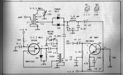
I was looking through W1FB's Design Notebook the other day and I came across the above schematic for a direct conversion receiver (page 111). Note the Polyakov detector. One strange thing though: Doug was running the oscillator at the operating frequency. I thought the big advantage of the Polyakov design was that you ran the oscillator at half the operating frequency (that's why it is sometimes called a "subharmonic" detector). Any ideas on why Doug did it this way?

Check out "SolderSmoke -- Global Adventures in Wireless Electronics"
http://soldersmoke.com/book.htm

Wednesday, April 20, 2011

SolderSmoke Podcast #133

http://soldersmoke.com/soldersmoke133.mp3

April 19, 2011

-- KindleSmoke
-- Amazon's Whispernet (not to be confused with WSPRnet)
-- April 1 and the Perils of Plausibility
-- The difference (significant!) between Cream of Tartar and Tartar Sauce
-- A short Italian lesson
-- Polyakov QRSS
-- Snort Rosin's Mighty Mite (NOTE: NO FILTER!)
-- Fly Fishing in Space: 2 Meter Packet Beacons and the International Space Station
-- Upside-down Amplifier
-- Rock and Roll and Ham Radio: The Bob Heil Story
-- The Shuttle Discovery Lands in Northern Virginia
-- MAILBAG

Check out the new Ikea Microphone!

Monday, April 4, 2011

The Polyakov QRSS Receiver

Of course, we like it because it is in an Altoid-like box. And because it is Direct Conversion. And because it is used for QRSS, with the output fed to an on-line grabber. But this one is EVEN BETTER because it uses a Polyakov detector!

Check out PA1GSJ's receiver: http://www.qsl.net/dl1gsj/html/qrssrx30.html

View the output (live): http://www.qsl.net/dl1gsj/qrss/

More on Polyakov detectors: http://soldersmoke.blogspot.com/search?q=polyakov

Tuesday, March 30, 2010

AA1TJ on Polyakov, Scrounging Parts from a Wehrmacht Tank, QRPp Success

Caro Bill, FB on your 20mW DSB WSPR DX! I've never actually been on the air during the upside of a solar cycle. This is wicked exciting! Thank you for the nice write-up on your Soldersmoke Blog, OM. I heard back from Fabio this morning; he seems to be as excited as I am (please see his message below). Italy is my fourth DX contact and third country with 10mW. Two weeks ago I worked F5NBX twice and FM5LD once. Again, all great fun... I'm glad to hear of your interest in the Vladimir Polyakov's mixer. I can attest to Vlad's claim about its resistance to SWBCI. So far, I've used silicon and germanium diodes, MOSFETS, and even a saturating inductor for the subharmonic, commutating switches. I haven't mentioned it till now, but leading up to my Gigi regenerodyne receiver, I built Polyakov reflexed 40m receiver that was lots of fun. The RF input signal first passed through a simple BPF on its way to the cathode of a triode, grounded-grid RF amplifer. The amplified signal next passed through the Polyakov anti-parallel diodes. The resulting AF signal was then re-injected into the grid of the same triode (now working as a common-cathode amplifier). In typical "reflex' fashion, the same tube amplifies first at RF and again at AF. Looking at my notebook entry, I was able to "plainly hear" a 1.0uVrms signal and in a week of operation I hadn't noticed any SWBC breakthrough. Actually, the subharmonic mixer was well-known by 1976, but I'd never seen it used by hams at HF until Polyakov popularized the idea. Our Eastern European comadres took a liking to it right away but it took some time before it finally caught on in the West. By the way, I had a short email exchange with Vladimir a few months ago. I'm pleased to report he's a really nice fellow. He happened to mention that his first amateur radio transmitter was built using parts that he salvaged from an abandoned Wehrmacht tank. It seems radio components were extraordinarily hard to come by in those days. Amazing... Have fun, Bill! Mike, AA1TJ ---------- Forwarded message ---------- From: Fabio Ventrone Date: Sat, Mar 27, 2010 at 9:16 AM Subject: Re: IZ0PEC de AA1TJ/QRPp To: Michael Rainey Dear Michael, Many many compliments for your qrpp station! Really exciting to have qso in this conditions... It's actually the first time I can connect qrpp oversea... Unbelievable, something we can tell our friends forever!!! I was transmitting with 4 el antenna and something more than 100w. I will have to take back my 817 and try to call dx as you bravely did!!! Best 73 qsl Fabio de IZ0PEC 2010/3/26, Michael Rainey > Dear Fabio, > > Thank you for your patience in copying my signal on 20m CW this evening. I > had been calling DX stations for several hours but you were the only one to > answer. My homebrew rig has an output power of only 10mW (0.010 watts). The > distance between us is 8793km; nearly one million km per Watt!. The antenna > here is simply an end-fed wire. > > I am amazed that you heard my 10mW signal in Rome. It's fantastic! > > Again, thank you for patiently listening for my weak signal, OM. It would > not have been possible without your very kind efforts. > > Ciao, > Mike, AA1TJ

Saturday, March 27, 2010

Polyakov Plus! Dual-band Receiver with Subharmonic Mixer

I found it! SPRAT 110, Spring 2002, page 5. A short article by OM Rudi Burse, DK2RS. This is the variation on the Polyakov Russian Mixer that I mentioned a couple of days ago. I'd been digging through piles of books and old magazines looking for this. My wife thought I'd gone nuts. (Well, nuttier than usual, actually.) It didn't help that I responded "The Polyakov Russian sub-harmonic mixer circuit with two band application!" when she asked what I was looking for. Of course, I should have known that it was in SPRAT. It just happened that the issue with this article was piled under a lot of junk on the workbench. I really like this circuit. Ingenious. And now that I have come to understand mixers a bit better, I can appreciate this one more. Here's how I'd explain it: With the switch closed, the signal from the LO "opens" one of the diodes on the positive peak, and it opens the other diode on the negative peak. So that RF signal from the antenna is getting sampled and mixed twice each cycle of the LO. The resulting complex waveform has sum and difference frequencies of RF+2LO and RF-2LO. With the switch open, you only have one diode sampling the RF, and it opens only ONCE each LO cycle. So the complex waveform that comes out of this single diode had frequencies of RF+LO and RF-LO. This opens the possiblity of DC receivers for 80/40, 40/20, 20/10 meters, etc. I guess a key adjustment in this circuit would be getting the LO level just right. Thanks SPRAT! Thanks Rudi! Thanks Vladimir Polyakov!

You'll see in the comments attached to my last blog post that our man on the left coast, Steve Smith, gave that cute little Doug DeMaw/Vlad Polyakov receiver a name that might set American-Russian hamrelations back a bit: He called it "Vlad The Inhaler." Good one Steve! (But you might want to stay out of the diplo game!) 

Check out "SolderSmoke -- Global Adventures in Wireless Electronics" http://soldersmoke.com/book.htm

Thursday, March 25, 2010

Polyakov's Russian Mixer

I'm planning on building a DC receiver for use with the WSPR system. I will probably follow W3PM's lead and put a crystal filter between the antenna and the mixer. This will be a fixed frequency receiver aimed at one 200 hz slice of the 30 meter band.

Of course, the big question is what mixer circuit I should use. I'll probably go with an SBL diode ring, but while perusing the literature, I again came across "The Russian Mixer" of Vladimir Polyakov, RA3AAE. Michael, AA1TJ, is a big fan of this circuit, and has been talking about it on Radio Havana Cuba. What a cool circuit it is! Just two diodes in parallel, cathode to anode. RF from the antenna goes in one side, and the local oscillator signal is placed at the other end. The LO signal causes the diodes to turn on and off on voltage peaks, effectively chopping up the incoming signal, producing sum and difference frequencies. LA8AK's drawing of one version of this circuit appears above. (Obviously OM AK didn't like this configuration, but it gives you the idea.)

The really cool part is that because you have two diodes, the "chopping" takes place at TWICE the LO frequency. This happens because on a positive LO peak one of the diodes conducts, and then, on the negative peak, the other conducts. So it is as if the mixer gate is opening twice each LO cycle. This allows you to run the oscillator at half the operating frequency, with advantages for stability and for the effort to eliminate common mode hum.

A while back I saw (somewhere!) a clever use of this circuit. LO was running at around 3.5 Mhz. With the two diodes in the circuit, it was a 40 meter receiver. They had a switch that could remove the second diode from the circuit. By throwing this switch, the RX went to 80 meters.

Does anyone remember this circuit? Where did it appear? SPRAT? QQ? Tech Topics? I can't find it.

I had the impression that OM Polyakov was active in the early days of radio. But some Googling shows that he is of much more recent vintage, still active and listed on QRZ.com. Here he is:
Designer: Douglas Bowman | Dimodifikasi oleh Abdul Munir Original Posting Rounders 3 Column