Serving the worldwide community of radio-electronic homebrewers. Providing blog support to the SolderSmoke podcast: http://soldersmoke.com
Podcasting since 2005! Listen to Latest SolderSmoke
Saturday, January 4, 2025
Donnie WA9TGT's Direct Conversion Receivers
Thursday, April 4, 2024
MXM SupeRX/TX 40 Rig Info
Click on schematics for a better view
Friday, March 29, 2024
A QRP CW Contact (Video) with the Winterfest MXM SupeRX/TX 40 (1 Watt, Crystal Controlled Transmitter)
I picked this transceiver up at Winterfest for one dollar. 40 meters. Superhet receiver with 455 kc ceramic filter and 2 NE602s. Crystal controlled one watt transmitter on 7039.5 kc. I emailed Jeff KA2BKG and asked him to slide up a bit to my freq. I am glad he did. Thanks Jeff.
Thursday, February 15, 2024
More Inspiring Mail! Another "First Ever Receiver was Homebrew"
It was great to hear from someone else who, like Scott KQ4AOP, heard his very first signals on a homebrew receiver. That is a really wonderful way to start. Frank's first receiver was built around the NE602 chip. I had trouble understanding this IC but I finally cracked the code:
https://soldersmoke.blogspot.com/2021/11/how-to-understand-ne-602-and-gilbert.html
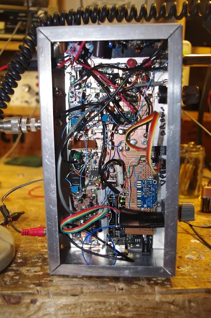
The picture that Frank sent is of a more recent project, this one a Lowfer receiver that picks up signals from beacons.
-------------------------
Hello Bill,
I just wanted to message you and tell you I really enjoyed your book Soldersmoke. I've been listening to the podcast as well. On the latest one you mentioned a fellow who heard his first ham radio signals on a homebrew receiver, and that's how it was for me as well! There were lots of articles about using the NE602 in the electronics magazines back in the day. I put one of the circuits together and it worked pretty smoothly... I eventually got my ham radio licence (KC8JJL) sometime in the 90's. The first time I met a ham was when I showed up to take the test!
Wednesday, December 1, 2021
KI4IO in India and Nepal, and Discrete Homebrew Gilbert Cells
While in India I was licensed at VU2LHO and worked a lot of US hams with a 135' flat-top and open-wire feed. I had the antenna strung between two bamboo towers atop the embassy housing 2nd-story roof-top. I also put up a 3/8 wave vertical on the roof for 10 meters. That little antenna had 110 radials stapled into the roof screen and worked very well! The rig was a HW-101. I was in Kathmandu, Nepal from early 1980 to late 1982. I could not obtain a license there, but became good friends with Father Moran, 9N1MM, and would often spend time up at his place putting his Drake station on CW. Pretty cool being real DX! Back in the states in late 1982.
Tuesday, November 30, 2021
Putting a Barebones Superhet on 17 Meters with an NE602 Converter (Video)
Sunday, November 28, 2021
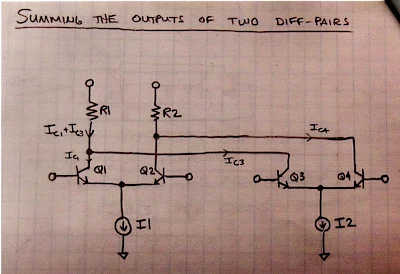
How To Understand the NE-602 and the Gilbert Cell Mixer
Tuesday, July 28, 2020
A 75 Meter AM Quarantine Converter for the Q-31 Receiver (video)
A while back Fred KC5RT sent me a nice collection of parts, including some 6 MHz crystals. I had been thinking of making a converter to put ahead of my Q-31 receiver. When Fred's 6 MHz rocks arrived, I knew that The Radio Gods Had Spoken (TRGHS).
I found some NE602 chips in the junk box. I used an Altoid-sized box for the case. The toroids are from W8DIZ. I use trimmer caps from KC5RT to resonate the input and output circuits.
Hooray! Now I can listen to 75 Meter AM on the Q-31. I may have to build a transmitter to go with this contraption.
Thanks again Fred.
Sunday, July 2, 2017
AC9JQ's Mini Digi VFO/BFO Al Fresco with OLED (and noise test)
From Dean AC9JQ:
Just completed the VFO/BFO/Arduino/OLED module for my radio. I also have the LPF, BPF and crystal filters completed and tested. Next will be the audio amplifier and NE602 modules. I will probably build one of the NE602 modules and test things out as a DC receiver. My ultimate plan is to have the rig no more that 1"x3.5"x3". I still have a lot of "stuff" to stuff into that size of box. I'll keep you posted.
I have been able to contain the entire Arduino/Si5351/OLED into a small cube in the front. The rest of the radio has to fit on two levels in the rest of the area behind the Arduino/Si5351/OLED. I think I will build the audio section and on NE602 mixer and run it as a direct conversion first to vet out any noise or other problems. Bill, that small coax that you pointed out will really help on this build. I used a small piece as a power feed-thru and will use it to feed out the VFO/BFO signals, thanks again for that pointer.
I decided to test for noise on the TIA transceiver test bed. See the video of the results. Not too much noise. I'm only using my indoor magnetic loop for an antenna. Video is kind of sloppy, but taking off the antenna and turning up the volume shows how little noise is left in the system. Now time to stuff the rest of the radio into the tight quarters.
IIC interface. OLED display, no need backlight, self-illumination, the display performance is better than the traditional LCD display, also lower consumption. VCC: Power (DC 3.3 ~5v). Display Color:Blue. | eBay!
| ||
Saturday, June 17, 2017
SolderSmoke Podcast #197: Farhan, Fame, 'Fest, Testgear, SSB History, Dishal Dystopia, QRP CW, MAILBAG
 |
| AI4OT and N2CQR |
 |
| N2CQR AND W2DAB |
Sunday, June 4, 2017
LTSpice .asc file for the Organic Chip NE602 Rig
Here is the .asc file: http://soldersmoke.com/NE602 Rig.asc
Saturday, June 3, 2017
My Organic Chip Rig with an LTSpice Schematic
This is a rig that came together through a process of Spontaneous Construction. It started out with an innocent effort to get an Organic Light Emitting Diode display to work with an Si5351/Arduino combination. Then I figured I'd make a superhet receiver with it. Then Pete said I should make it a transceiver.
Most of my earlier transceivers so closely followed the schematics of Farhan or others that it didn't really make sense for me to prepare a new schematic. This one was different. So I decided to prepare a proper schematic. I tried a few of the free-ware CAD or drawing programs, but each of them had a learning curve at the entrance. So I turned to LTSPICE. I have already climbed that learning curve.
The results appear above. Click on the image to make it bigger. I'm sure there are errors in there. And I think some of my parts choices might be less than optimal. But it works well.
The filter was deigned with the help of AADE software.
The idea of using two NE602s with a filter between them came (I think) from the Epiphyte.
The band pass filters were designed with ELSIE software.
The RF power chain is mostly from Farhan's BITX40 module, with the pre-driver and driver modified for a bit more gain. Farhan's amp is the most stable power amplifier I have ever used. It hasn't given me any trouble, even at 20 Watts. Strongly recommended.
The microphone amp is derived from the 741 op amp circuit used in the (in)famous Wee-Willy DSB rig.
The receiver AF amp also comes from Farhan's BITX40Module.
Please let me know if you spot errors or have suggestions for circuit improvement.
A link to the .asc LTSpice file appears below. Perhaps some brave soul more skilled in LTSpice than I am might want to turn this drawing into an actual simulation. Some of the parts (like the NE602s) have actual simulated components behind the drawings. Others (like the relays and the LM741 and LM386) are just drawings. But go ahead and flesh this thing out. Who knows, it might come to life in the PC and start making QSOs on 40!
Here is the .asc file: http://soldersmoke.com/NE602 Rig.asc
Sunday, April 23, 2017
DiFX! My New NE602 Rig is On the Air
Pete would call this a DiFX: a transceiver that is Different from a BITX. This started with my effort to get an Si5351 working with a little 1 inch square OLED screen. Tom Hall AK2B helped me with the software (thanks Tom). Once I got that done, I figured I could build a simple receiver with a homebrew 11 MHz crystal filter, two NE602 chips, and an LM386 AF amplifier. That was working great, then Pete told me to turn it into a transceiver. I used some of Pete's boards (thanks Pete).
The Epiphyte transceivers also use two NE602's, but they ingeniously switch the BFO and VFO between the two chips. I didn't switch the oscillators -- instead I switched the inputs and outputs of the two chips using two DPDT relays (thanks Jim). A third DPDT relay switches the antenna between T and R, and turns on and off the PA stage and the AF amplifier.
This is a DIFX, but there is some BITX circuitry in there. The power amplifier stages are right out of the BITX Module, as is the AF amplifier (thank again Farhan).
The only real problem I ran into had to do with the very low power out of the NE602 VFO mixer on transmit and the impedance matching between the NE602 and the PA chain. I had to increase the gain on the first RF amp (pre-driver) using ideas from Steve Weber's 40 meter SSB CW QST contest rig (thanks Steve). I experimented with various connections between the NE602 and the BP filter. Finally I got it going.
The heat sink on this one is different too: it is just the chassis. The IRF 510 is bolted (insulated) to the aluminum box.
I fired it up this afternoon and in spite of horrible conditions on 40, quickly had a nice rag chew with KJ4ZMV in Indiana. I haven't even built a mic amp yet! I am running the D-104 right into the NE602 balance modulator. There are no signs of unwanted modulation or spurs.
FB! TRGHS! VIVE LA DIFFERENCE!
Tuesday, October 25, 2016
VK3HN: SOTA, HB, SSB, and QRP FB!
Peter VK3YE sent me the link to this amazing site. Wow, Paul VK3HN does great work, both with the homebrew rigs and in describing his work on them. Check it out:
https://vk3hn.wordpress.com/2016/10/25/summit-prowler-one-a-homebrew-7mhz-ssb-qrp-transceiver-for-sota/
Great stuff. Thanks Peter! Thanks Paul!
Friday, May 2, 2014
Bert's EMRFD Direct Conversion Receiver
Very nice Bert. Sounds great. I like the pill bottle coil core. Lew McCoy used them in his designs. I do think that air core coils do provide better stability than ferrites or iron powder. I kind of like the SW broadcast background music. I also like the internal 9V battery. Glad to see someone else resurrecting an old DC RX project.
Our book: "SolderSmoke -- Global Adventures in Wireless Electronics" http://soldersmoke.com/book.htm Our coffee mugs, T-Shirts, bumper stickers: http://www.cafepress.com/SolderSmoke Our Book Store: http://astore.amazon.com/contracross-20
Wednesday, June 3, 2009
NA5N on the NE602

Here is a good one from NA5N.
Orignally posted on Gadgeteer news, 2 December 2006
(Originally posted by NA5N on QRP-L)
The ever famous NE602's are manufactured in the Philips
Semiconductor plant in Albuquerque, about 85 miles north of me. I visited
there last summer and had a nice discussion with an applications engineer
about the history of the NE602's. Goes something like this:
This long story will prove that NE602 = SA602 = NE612 = SA612
(for those of you who don't want the gory details -hi)
The original NE602 was designed/manufactured by SIGNETICS for
the 45MHz FM wireless telephone market. A little later, the wafer was
redesigned a bit to allow the internal oscillator to operate to 200MHz and the
RF to 500MHz. This was redesignated the NE612, and was intended to
replace the NE602. However, customers kept ordering the NE602, getting
angry at Signetics because their distributors were out of stock, etc. So when
they made the chips, they made a jillion NE612's, and labeled some of them
NE612 and the rest NE602 to satisfy the users of both parts. This is why
contemporary data books show the exact same specifications for both NE602
and NE612. They came from the same wafer.
Then Signetics was bought out by Philips, who evidently
continued this practice for a short time, then decided it was rather
redundant. So they announced that the production of NE602's has been discontinued
and listed it as an obsolete part ... giving QRPers around the world
various fits of apoplexy to suicidal tendencies that doomsday had struck.
What wasn't well understood is Philips continued to support production of
the NE612, as they do today.
Then to make matters worse, disaster struck the Philips plant
in Albuquerque in the spring of 2000. A wild grass fire in
northwest New Mexico threatened three main electrical lines that run from
the "Four Corners" electrical generating plant to Albuquerque. Smoke
from the fire caused one of the high-voltage lines to arc, tripping the
circuit off line. Virtually the entire electrical load for Albuquerque
and southern New Mexico was now transfered to the two remaining feeders,
which could not handle the full load, causing brownouts, voltage spikes,
etc. until they too failed. Where I live in Socorro, New Mexico, I
remember the brownouts hit about 4:15pm, outages on and off until the
entire grid went down about 5pm, and stayed off until about 11pm. One of the
longest power failures in US history. We just figured it was Y2K about 3
months late. (PS - I worked 40M CW QRP that night by candlelight, and it
was the quietest conditions I ever heard on 40M!!! And every QSO I
heard seemed to be a QRPer). The extreme voltage fluctations as the
feeders were failing caused a transformer at the Philips plant in
Albuquerque to catch on fire. I remember seeing it on the TV news, in which they
said it caused mostly smoke damage from the burning transformer and
burned a couple of storage rooms. That was all-no biggie. Well, it
turned out one of the storage rooms that was burned was where they stored
the film masters for making the semiconductor dies, and the NE612 film
master was now molten emulsion. These film masters were the originals
from the old Signetics company. So Philips had to completely redo the
artwork for the majority of their IC's. Additionally, it turned out the
smoke damage was excessive and the IC fabrication facilities were
left unusable. Philips was basically unable to manufacture IC's at
the Albuquerque plant for months. It was about 8 months before
they got all their wafer machines back on line, which left a huge hole in
the semiconductor industry. I know it just about killed several
cell phone manufacturers because delivery contracts for parts were
suddenly postponed for six to eight months.
The world wide supply of NE602/NE612's virtually dried up
during 2000 as a result of this fire and the nearly year backlog of
manufacturing quotas. The first run of NE612's in 2 years finally occured in
September 2000.This huge shortage of NE612's, combined with the fact that
NE602's have been discontinued/obsolete, is what convinved QRPers that
these nifty little chips were no more. I was told 20,000 units were
manufactured in 2000, or what Philips believes is a 2 year supply. This is
also why the release of the K1 (with 5 NE612's!) was delayed from the
promised "after Dayton" to late in the year, as were other kits. It just
wasn't clear when Philips was going to schedule the NE612's for production.
So yes, the NE602 is dead, but the perfectly compatible NE612
is still available, and Philips has no plans at the present to
discontinue that part number.
For final clarification:
NE602 = plastic DIP, rated 0C to +70C ... OBSOLETE
SA602 = plastic DIP, rated -40C to +85C ... OBSOLETE
NE612 = plastic DIP, rated 0C to +70C ... AVAILABLE
SA612 = plastic DIP, rated -40C to +85C ... AVAILABLE
or, to answer the final question ...
NE602 = SA602 = NE612 = SA612
Saturday, February 21, 2009
W3JDR 's LTSpice NE602/SA612
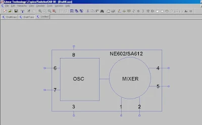 Here's something we've needed for a long time: an LTSpice model for the ever-popular NE602/SA612 chip. Joe Rocci, W3JDR, developed this one back in December. You can download it, along with the LTSpice program (free!) from links on Joe's page:
http://w3jdr.ham-radio-op.net/ Thanks a lot Joe!
Speaking of Spice, Jim, AL7RV, has been e-cursing me for getting him involved with this highly addictive program. Jim has come up with an ingenious idea for making the simulation experience more realistic. I will tell you all about it in the next podcast.


