Serving the worldwide community of radio-electronic homebrewers. Providing blog support to the SolderSmoke podcast: http://soldersmoke.com
Podcasting since 2005! Listen to Latest SolderSmoke
Monday, June 19, 2023
CuriousMarc Repairs an old DISCRETE COMPONENT HP Frequency Counter
Friday, March 3, 2023
My HP8640B Signal Generator Lives Again
I'd really come to like this old signal generator. The construction is superb. It was built to be repaired. As you open it up you find all kinds of useful diagrams and pointers. It is very solidly built - it looks like something that was built for the Apollo program. And it was given to me by a friend: Steve Silverman KB3SII gave it to me in 2017 -- he had it in his New York City shack. Dave Bamford W2DAB picked it up for me just before Steve moved out of the city.
I've already done one complex repair on it -- one of the tines on one of the selection switches fell of and I had to replace the tine. That was difficult, but it was a very satisfying repair.
But lately, the HP8640B started acting up again. It developed an intermittent problem that caused both the signal generator and the frequency counter to just shut down.
I was thinking that this might be the end of the road for the HP8640B. I even started looking for alternatives. But they were all very unappealing. They come in plastic boxes with names like Feeltech and Kooletron. The boxes are filled with flaky wiring and boards hot glued to the plastic. Yuck. The contrast with the HP8640B could not be stronger.
So I started to think about the problem. This was the first part of the troubleshooting process. I asked myself: What would cause several different systems (counter, frequency generator, and display) to all shut down? The power supply was a leading candidate.
I started reading the power supply section of the HP8640B manual. There was a line in there that caught my eye: The power supply boards had on them LEDs that glowed if the board was functioning. Thank you Hewlett Packard! I opened the top of the signal generator and found the power supply boards. Sure enough, there were the LEDs. I turned the generator on, and found that one of the lights was out. Bingo. (Trevor takes a look at the power supply boards in the video above. I have it cued up to the 12:57 point at which he talks about and shows these boards.)
Here was the other clue: The problem was intermittent. It kind of seemed like a loose connection. So I just unseated the board and took it out. I put some De-Oxit on the connector and popped it back in. Boom: The LED came on and the HP8640B came pack to life.
There is a whole bunch of great info and videos on the HP8640B on the internet. It is almost as if a cult has developed. This signal generator is worthy of a cult following. Count me in.
I especially liked the video below. Kevin really captures the admiration that many of us feel toward the way this piece of gear was built. He also kind of hints at the way this sig gen could become a pirate transmitter on the FM broadcast band (at 8:44):
I know that eventually the problematic plastic gears in this device might fall apart. I am prepared for this: I already have the metal replacement gears from India.
Thanks again to Steve Silverman KB3SII and Dave Bamford W2DAB for bringing me into the HP8640B cult.
Saturday, June 11, 2022
Putting the "Mate for the Mighty Midget" Back to Work -- With a DX-100 on 40 Meter AM
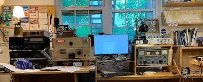
After working on it for a while I got so fond of my old Hammarlund HQ-100 that I moved it from the AM/Boatanchors operating position over to a more convenient spot right next to my computer. This left a big gap on the receive side of the AM station.
I briefly put my HRO-ish solid state receiver above the DX-100, but I'm afraid that receiver needs some work. More on that in due course.
I thought about putting my SOLID STATE Lafayette HA-600A atop the thermatronic DX-100, but this just didn't seem right. The Radio Gods would NOT approve.
So I turned my attention to the Mate for the Mighty Midget that I built in 1998 and have been poking at and "improving" ever since.
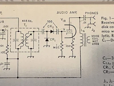
This receiver worked, but not quite right. It received SSB stations well enough, but when I turned off the BFO I could no longer hear the band noise. I wasn't sure how well the RF amp's grid and plate tuned circuits tracked. And I had serious doubts about the detector circuit that Lew McCoy put in there when he designed this thing back in 1966.
As I started this latest round of MMMRX poking, I realized that I now have test gear that I didn't have in 1998: I now have a decent oscilloscope. I have an HP-8640B signal generator (thanks Steve Silverman and Dave Bamford). I have an AADE LC meter. And I've learned a lot about building rigs.
FRONT END TRACKING
The MMRX has a tuned circuit in the grid of the RF amplifier, and another in the plate circuit of the RF amplifier. There is a ganged capacitor that tunes them both. They need to cover both 80/75 and 40 meters. And they need to "track" fairly well: over the fairly broad range of 3.5 to 7.3 MHz they both need to be resonant at the same frequency.
McCoy's article just called for "ten turns on a pill bottle" for the coils in these parallel LC circuits. The link coils were 5 turns. No data on inductance was given. Armed now with an LC meter, I pulled these coils off the chassis and measured the inductances of the coils. I just needed to make sure they were close in value. They were:
L1 was .858uH L2 was 2.709 L3 was .930uH L4 was 2.672
Next I checked the ganged variable capacitors. At first I found that one cap had a lot more capacitance than they other. How could that be? Then I remembered that I had installed trimmer caps across each of the ganged capacitors. Adjusting these trimmers (and leaving the caps connected to the grid of V1a and V2A, I adjusted the trimmers to get the caps close in value. I think I ended up with them fairly close:
C1: 63.77-532 pF C2 64.81 -- 525.1 pF
I put the coils back in and checked the tracking on 40 and on 80/75. While not perfect, it was close enough to stop messing with it.
DETECTOR CIRCUIT
I've had my doubts about the detector circuit that Lew McCoy had in the MMMRX. In his 1966 QST article he claimed that the circuit he used was a voltage doubler, and that this would boost signal strength. But I built the thing in LT Spice and didn't notice any doubling. And consider the capacitors he had at the input and output of the detector: 100 pF. At 455 kHz 100 pF is about 3500 ohms. At audio (1 kHz) it is 1.5 MILLION ohms. Ouch. No wonder years ago I put a .1 uF cap across that output cap just to get the receiver working.
Scott WA9WFA told me that by the time the MMMRX appeared in the 1969 ARRL handbook, the second "voltage doubling" diode was gone, as were the 100 pF caps. Now it was just a diode, a .01 uF cap and a 470,000 ohm resistor. I switched to the 1969 Handbook circuit (but I have not yet changed the 1 meg grid resister to 470k -- I don't think this will make much difference). Foiled again by a faulty QST article, again by one of the League's luminaries.
6U8s out, 6EA8s in
We learned that the 6U8 tubes originally called for by Lew McCoy are getting old and not aging well. So I switched all three to more youthful 6EA8s. This seemed to perk the receiver up a bit.
MUTING from the DX-100
My K2ZA DX-100 has a T/R relay mounted in a box on the back of the transmitter. When the Plate switch goes up, it switches the antenna from receiver to transmitter. The box also has a one pole double throw switch available for receiver muting. I put the common connection to ground, the normally connected (receive position) connect the ground terminal of the AF output transformer to ground -- it is disconnected from ground on transmit. The other connection (normally open) is connected to the antenna jack -- on transmit this connection ground the receiver RF input connection. These two steps mutes the receiver very nicely.
Replacing Reduction Drive
Over the years I have had several different reduction drives on the main tuning cap. I had a kind of wonky Jackson brothers drive on there that needed to be replaced. I put in a new one -- this smoothed out he tuning considerably.
Ceramic Resonator
I never could get McCoy's 455 kc two crystal filter to work right. So at first I made due with the two 455 kc IF cans. This made for a very broad passband. Then I put a CM filter in there. This was more narrow, but with a lot of loss. There may have been others. But the filter spot is currently held by a 6 kHz wide ceramic filter. This one is my favorite so far.
Digital Readout
When I was running the DX-100 with the Hammarlund HQ-100 I built a little frequency readout box. The box was from a Heath QF-1 Q multiplier (I am sorry about this). The readouts are in Juliano Blue and come via e-bay from San Jian. I now have it hooked up to the DX-100's oscillator. I haven't tapped into the MMMRX's oscillator yet.
Tuesday, May 24, 2022
Sticker Shock -- WYKSYCDS Stickers Spotted in NYC and in a Netherlands Pub! Awards!
Thursday, September 10, 2020
The Agony of Troubleshooting -- From China
I became hopeless, and ordered several LM732,and waiting delivery for days. This beast frustrate me so deeply, changed the LM723 does not help anything. And i almost desoldering everything in the board!
Oh man, I've been there. Several times while in the throes of a troubleshooting battle I have actually had dreams of removing all the parts from a troublesome PC board.
BH1RBG has a very interesting site with lots of ham radio projects:
https://sites.google.com/site/linuxdigitallab/rf-ham-radio?authuser=0
Sunday, May 26, 2019
DIY Waterfall -- A Quick and Easy Panadaptor Using a Sig Gen and O'scope (video)
Anyway, in an effort to counteract all of this waterfall seduction and to show that us analog HDR guys can go panoramic too, I decided to try to create my own panoramic display without resort to SDR.
Of course, this is a very old technique. It was invented in the 1930s by Marcel Wallace, F3HM. He was the inventor of the Panadaptor which was the forerunner of today's waterfall. Panoramic reception was used by the armed forces during WWII. In 1946 Hallicrafters marketed a Panadaptor for its ham radio receivers (see below).
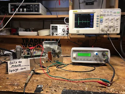
In figuring out how to do this, I thought back to my use of my Feeltech signal generator to scan the response of a crystal filter. The Feeltech has a very handy sweep feature.
In this case I set up the Feeltech to sweep from 4.85 MHz to 4.75 MHz in one second. With the 12 MHz IF of the BITX40 module, this would result in a sweep from 7.150 to 7.250 MHz.
The sweeping Feeltech just replaced the VFO on my BITX. I hooked up the Rigol oscilloscope to the audio output of the BITX. I set the horizontal scan rate at 100 ms per cm. This would have the trace go across the whole screen in 1.2 seconds.
After a bit of fiddling, I could see signals on the 40 meter phone band. But my display would kind of drift along the screen making it hard to know the frequency of the signals I was seeing.
Alan Wolke W2AEW provided the solution. He advised me to put a big stable signal at 7.150 MHz near the input of the BITX, then use this strong signal to trigger the 'scope scan. The HP8640B signal generator that Steve Silverman gave me (and that Dave W2DAB picked up for me in NYC) provided the triggering signal.
I put a piece of tape across the bottom of the scope display to calibrate the display. See video above.
It works! It is not as cool as the SDR waterfalls, and it does not convey nearly as much information, but it was a fun project.


