Podcasting since 2005! Listen to Latest SolderSmoke

Showing posts with label wolke -- Alan. Show all posts

Wednesday, October 16, 2024

SolderSmoke Podcast #253 AUDIO VERSION: NYC, SF, DR, PC, DSC, PODCAST IN DANGER, SPRAT, sBITX, CW, IMD, AI, PNP, MAILBAG


SolderSmoke Podcast #253 is available:  

 http://soldersmoke.com/soldersmoke253.mp3

October 16, 2024

Sponsor!  Parts Candy is back!  Handmade in Chicago!  Standard test leads,  Hook clips, alligator clips in 12" and 32" and multimeter leads

Travelouge/Intro

Bill's trip to NYC -- The Empire State Building

Dean goes to the Bay area. 

Harry Caul,  Marty Klein W3VCG , "The Conversation" and THE KNACK.https://soldersmoke.blogspot.com/2024/08/harry-caul-had-knack-movie-review.html

Joe Piscopo in Bell System video! https://soldersmoke.blogspot.com/2024/08/soldersmoke-quiz-question-who-is-actor.html

Bill's Bench 

Bill's report from SolderSmoke Shack South: The tropics:  What this means.  Guapo wouldn't  go out when the sun was overhead. 

 Skies not great for astronomy now.  But we see a lot of satellites, and meteors.

Antenna developments:   1/4 vertical on a fishing pole.  

Lightning suppression coming for the building. Lightning suppressors.  Got 2.  Good video from the IMSAI guy: https://www.youtube.com/watch?v=7EyABPuNDMA Argon gas suppresion tubes.Need to crimp! 

Hurricane prevention. Metal storm curtains. 

Thinking of solar panels. 12 panels, 5 kW system.  Probably without batteries.  What do you think? 

A golf cart. 

New PC.  BeeLink.  Very tiny! (palm of your hand)   24 inch screen. Works well https://www.amazon.com/dp/B0BVFKN7ZL?ref=ppx_yo2ov_dt_b_fed_asin_title&th=1

A very satisfying fix on the 15/10 rig -- loose connection to RF amp.  The highly suspect Ramsey Kit Amp was NOT the culprit!  Got to use the new Rigol DS-1102.  A fun fix. Will build a second CCI amp. 

Digital Selective Calling -- listening to ships and shore stations on HF.  https://soldersmoke.blogspot.com/2024/10/monitoring-maritime-radio-messages-with.html

SHAMELESS COMMERCE:  Our blogs and the podcast are in danger!  Pete is already on a permanent  blog hiatus.  I have seen a big decline in readership.  Frankly, if no one is reading or listening, we just may decide not to do it anymore.  We don't want to do this.  So please, link to the blogs.  Talk up the blog and podcast on your own blogs and social media.  

Parts Candy Test Leads are back as our sponsor.  Pete has them.  Dean has them, I have them in two different countries!     DON'T SCRIMP WITH A CRIMP!  

SPRAT Summer 2O24 Special EXTRA 50th Anniversary issue! https://www.gqrp.com/sales.htm

Dean's Bench

First CW contact:  With KK4DAS on his HB sBITX  and  Alan W2AEW POTA.  TRGHS. 

Dean fixes the sBITX problems. Again.  SUB-THRESHOLD CONDUCTION!    Lots of patience and stick-to-it-ivness. LPF leakage!  https://kk4das.blogspot.com/2024/08/homebrew-sbitx-lpf-leak-stopped.html

IMD IMD IMD and the Tiny SA Ultra https://soldersmoke.blogspot.com/2024/09/sherwood-its-time-to-clean-up-our.html

AI  AI   AI -- Experimental AI Podcasts about SolderSmoke (no kidding -- (NOT April 1) Where they came from https://soldersmoke.blogspot.com/2024/09/where-ai-podcasts-came-from.html 

AI Podcast #2 https://soldersmoke.blogspot.com/2024/09/here-is-another-short-podcast-about.html

AI Podcast #1  https://soldersmoke.blogspot.com/2024/09/a-new-experimental-podcast-about.html

Pete's Bench

 An all PNP rig -- A notional look, https://n6qw.blogspot.com/2024/08/august-30-2024-pnp-20m-ssb-transceiver.html 

Videos on old Boatanchors. https://www.youtube.com/watch?v=mnboJ75NCmY&t=1s

MAILBAG:  

Lex PH2LB making some new stickers.  Look out San Francisco!  

Rogier PA1ZZ sending lots of good ideas and links. 

Todd K7TFC  great idea on SS readersip decline 

Todd VE7BPO  aka Vasily -- great info on how to stabilize LC oscillators. https://soldersmoke.blogspot.com/2024/09/qrp-homebuilder-shows-us-how-to-build.html

Eric 4Z1UG  Welcome words of encouragement on the blog and podcast 

Dave W2DAB says that AI just can't replace the Tappit Brothers of ham radio.  Now the Tappit Triplets. 

Michael AA1TJ  Thoughtfully skeptical about AI. 

Grayson K7JUM on the cleanliness of the 32S-3. Also amazing video on Thermatron MMM. 

Mike WN2A working on DC receivers and hum! 

Floran OE7FTI building Farhan's JBOT amp! 

Mike Murphy WU2D building 1930 replica rigs using a Frank Jones circuit 

Dave K8WPE always great to hear from such a strong SolderSmoke supporter. 

Walter KA4KXX  Great ideas from the Wizard of Orlando. 

Paul G0OER -- Reacting to the 1970s Ham Radio video. Didn't remember being so cool. 

Thomas K4SWL -- Struggling with the hurricane in NC.  Hang in there OM. 

Nick M0NTZ building another Direct Conversion receiver -- with videos about it.

Michael AG5VG building a Mythbustrer-style 20 meter rig.  FT-101 VFO.  FB

Tony G4WIF -- Readership problem advice 

John AB2XT sent us 6000 47 pf NP0 capacitors.  So we are now good for caps!   Thanks John. 

Paul VK3HN Was suitably impresses by the AI podcasts we put on the blog. Thanks Paul. 


SolderSmoke Podcast #253 VIDEO VERSION : NYC, SF, DR, PC, DSC, PODCAST IN DANGER, SPRAT, sBITX, CW, IMD, AI, PNP, MAILBAG

SolderSmoke #253 is available in video form.  See above or: 

https://www.youtube.com/watch?v=DQBojTLL7VY

The audio version is available in the post immediately above this one, here: 

https://soldersmoke.blogspot.com/2024/10/soldersmoke-podcast-253-audio-version.html


Wednesday, May 8, 2024

Why we have "BW Limit" Switches on our Oscilloscopes

Dean KK4DAS asked me why we have these switches on our 'scopes.  I didn't know.  Dean asked Alan Wolke W2AEW.  Alan knew: 

Alan Wolke wrote: 

Interesting background on the 20MHz vertical BW selection. This feature has existed on the vast majority of all oscilloscopes since the 50s or 60s (both analog & digital). When I explored the history of this, I spoke to some of the folks at VintageTek.org, and wound up having a chat with THE engineer that did it first!  Tt was John Addis, designer at Tektronix. 

At the time, Tektronix was located in Portland Oregon. While working on a wideband vertical preamp for a new scope (the 7A11 vertical plugin for the 7000 series scope), John Addis was plagued with interference from the local television broadcast station in the 50MHz band. So, he popped in a 20MHz low pass filter that he could switch in/out so that he could complete the work on the preamp. Since it was deemed useful, it was left in the design. 


And, since Tektronix added a switchable 20MHz low pass filter  in their scope, and Tek was the leader in oscilloscope technology, other manufacturers followed suit, and this feature has "stuck" as a staple in vertical setting controls. 


The main reasons you'd use this filter would be to improve the signal to noise ratio (SNR) for signals when their frequency content is below 20MHz.   You've probably noticed that, even without any signal connected, the thickness of the trace is thinner when you engage the 20MHz filter. 

---------------------


Alan sent a link to a Wiki page about the 7A11 that John Addis was designing.  Alan says this places the initial inclusion of the 20 MHz BW Limit filter to the mid 1960s: 


https://w140.com/tekwiki/wiki/7A11


Thanks Dean, thanks Alan!  

Thursday, March 16, 2023

A Very Cool Video with NanoVNA, FFT, LC circuits, W2AEW, CuriousMarc, Back-to-Back 1N4148s, and String-Powered Gyroscopes


Don't let the scary nuclear chemistry title put you off -- there is a LOT of very familiar homebrew stuff in this video.  You will feel right at home.  Many of the resonances take place in the ham bands.   The CBLA may have to get involved here. 

Thanks to Chuck WB9KZY for sending this. 

And check out Ben's video on is best projects from the last 10 years: 

Thursday, October 6, 2022

Adding a Diode Ring to the Direct Conversion Receiver, And How the Diode Ring Works


I take a look back at Wes Hayward's classic DC receiver from the November 1968 QST.
I then try to describe how diode ring mixers work ("the particular go of it") using Alan Wolke's excellent YouTube description as my base.

I present some drawings that I did that use the "crossed diode" diagram as the start.

I also discuss interference from Radio Marti's 250 kW transmitter on 7335 kHz in Greenville NC.

Finally, we listen to the receiver a bit.

Alan Wolke's Diagram

Wes Hayward's 1968 DC Receiver

Friday, December 3, 2021

Alan Wolke W2AEW: YouTube Silver Play Button Award, and ARRL Hudson Division 2020 Technical Achievement Award

Three cheers for Alan Wolke W2AEW, truly one of the great guys of homebrew ham radio.  Alan's wonderful YouTube videos have enlightened hams all around the world.  He is always there to answer questions and help hams (like me) who are at times struggling to understand technical concepts. 

Photo from the November 13, 2021 ARRL Hudson Division Awards Luncheon. That’s Alan with the ARRL CEO David Minster NA2AA, the Nobel Prize winning Dr. Joe Taylor K1JT, and 2021 Technical Achievement winner David DeCoons WO2X. Alan was presented with the division’s 2020 Technical Achievement award. 

Sunday, November 28, 2021

How To Understand the NE-602 and the Gilbert Cell Mixer


I think the key to understanding the Gilbert Cell Double Balanced mixer is to separate out the three tasks that this device completes, and consider them one at a time, using different diagrams: 

1) It mixes two signals to produce sum and difference outputs. 
2) It balances out the RF input. 
3) It balances out the LO input. 

                                                                  Task 1 -- Mixing


The Gilbert cell is like the diode ring mixer in that it switches the polarity of the input signal at a rate set by the Local Oscillator. Another way of saying this is that the mixer multiplies the input signal by 1 and by -1. 

Steve Long of the University of California described the essence of this mixing this way (using the diagram above): 
 
An ideal double balanced mixer simply consists of a switch driven by the local oscillator that reverses the polarity of the RF input at the LO frequency.  http://literature.cdn.keysight.com/litweb/pdf/5989-9103EN.pdf

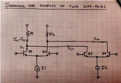
In an effort to see this for myself, I drew (noodled!) this diagram: 


There are four transistors -- two differential pairs with RF coming into the bases of the pairs. 
The LO is a square wave.  The LO alternately turns on transistors 1 and 4, then 2 and 3.  When 1 and 4 are on, we are in period 1 -- here there is no switching of polarity.  Portions of the RF waveform are passed to the outputs.  But when the LO turns on transistors 2 and 3, portions of the RF wave form are "crossed over" to the opposite output.  Polarity is reversed.  We see this in period number 2. 

Take a look at the resulting output waveforms.  This is the same waveform we see coming out of a diode ring mixer.  I really like this drawing because in that complex waveform you can actually see the sum and difference frequencies: 


I could see this diode ring waveform myself on my oscilloscope: 


TASK 2 -- Balancing Out the RF Input 

In a diode ring, and in other diode mixers, the balancing out of the input signals really takes place in the trifilar toroidal coils that are part of the circuit.  Barrie Gilbert needed an integrated circuit mixer that did not use coils.  


Again referring to the above diagram, Steve Long of the University of California put it this way: 

The ideal balanced structure above cancels any output at the RF input frequency since it will average to zero.

To fully understand this I find it helps to look at the Gilbert cell circuit drawn in a different way.  Here is a drawing from Alan Wolke W2AEW that I found very helpful. It comes from his excellent YouTube video: https://www.youtube.com/watch?v=7nmmb0pqTU0


Suppose the RF waveform at I1 is causing the current through R1 and R2 to increase.  At the same time, the opposite phase current through I2 will be causing the current through R1 and R2 to DECREASE.  So there is no net effect of the RF signal at the output.  The RF is balanced out. 

TASK 3 - Balancing Out the Local Oscillator Signal 


Here too I used my own drawing, and was guided by the words of Steve Long: 

It also cancels out any LO frequency component since we are taking the IF output as a differential signal and the LO shows up as common mode.  

The important thing to realize here is which transistors are being turned on and off by the local oscillator signal.  On one half cycle of the LO, transistors 1 and 4 are on.  So  the LO signal at the LO frequency are both pulling the same amount of LO frequency current through the resistors. So you have the same change in voltage at the output terminals.  And the output terminals are differential.  The LO signal results in no voltage difference between the terminals.  So the LO frequency is balanced out. 

The same thing happens on the following half of the LO cycle.  Here, transistors 2 and 3 are turned on. Again, both transistors pull the same amount of LO frequency current through the resistors. There is no differential voltage.  So no LO frequency energy passes to the output.  LO frequency is balanced out. 

--------------------------------

I am surrounded by Gilbert Cell Mixers and I have been using them in my homebrew rigs for many years. I use them in up-converters for my RTL-SDR receivers.  I have one in the downconverter for my 17 meter receiver and had one as the mixer in my first SSB transmitter. I built a 40 meter SSB transceiver with NE602s on either end of the crystal filter. Years ago, I built a DSB transceiver with several NE602s.  My SST QRP CW transceiver is made with NE602s. I have on my bookshelf Rutledge's book "The Electronics of Radio" that is all about the NORCAL 40 transceiver, built using NE602 chips.  But until now I really didn't know how these chips worked.  Truth be told, for me they were mysterious little black boxes, and that bothered me.  Now I feel a lot better about using these clever devices.  I plan on stocking up on the old style (non-SMD) NE602s.  

Apparently Barrie Gilbert rejected the idea that he invented the circuit that bears his name.  It seems that Howard Jones first used this circuit in 1963, with Gilbert developing it independently (in an improved form) in 1967. 

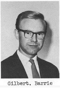
 Barrie Gilbert was quite a guy, with electronic roots in the world of tinkering: 


Friday, August 27, 2021

SolderSmoke Podcast #232 -- Mythbuster, Pete's Tube CW Rig, Pete's DC RX and Simple SSB Rig, NanoVNA and TinySA, Very FB Mailbag


SolderSmoke Podcast #232 is available -- Crank it in Robert!


Featuring a guitar intro by Pete "Bluesman" Juliano,  playing his own composition: "Juliano Blues." 

Upcoming GQRP convention and the N6QW rig
Frank Jones and the FMLA -- Possible Victory?
IBEW Stickers:  NASA, Johns Hopkins APL....
Cycle 25 Lookin Better Today:  SFI 93   SN 47
 
Pete's Bench:
Toobular!  A Tube Transmitter
SR-160
Simple SSB rigs around the world! 
KI7NSS's Pacific 40
 
Bill's Bench
The Mythbuster and the Struggle Against the Urban Legend
W2EWL's Cheap and Easy SSB
W4IMP's IMP. Articles in ER by Jim Musgrove K5BZH and Jim Hanlon W8KGI
The Spirit of Homebrew SSB. From Electric Radio K5BZH December 1991
Reduced Front End Gain on the DIGITIA
Back on 17!  HP3SS sells HBR receiver to Joe Walsh
Maybe another Moxon?
 
SHAMELESS COMMERCE DIVISION
 
Test Gear
NanoVNA -- Alan W2AEW helped solve mystery of why NanoVNA not providing accurate readout of circuit impedance.  Over driving.  Need attenuator. 
TinySA -- Limited Resolution Bandwidth.  But you can listen with it!  See video on blog.
 
MAILBAG
-- Google Feedburner to end e-mails from the blog :-(
-- Paul VK3HN -- TIA AGC? Farhan and Paul looking into options 
-- Ciprian's Romanian Mighty Mite
-- Dino KL0S SolderSmoke GIF and graphical presentation on sideband inversion
-- Allison KB1GMX helped me on 24 volts to IRF 510 issue.
-- Dave K8WPE Wabi Sabi and Martha Stewart. And thanks for parts!  40673s!
-- Steve N8NM building a 17 meter rig with 22.1184 crystals in a SuperVXO and a 4 MHz filter.  
-- Dean KK4DAS restoring an old Zenith.  One hand behind your back OM. 
-- Pete Eaton debating SSB or DSB for 17.  Go DSB Pete!
-- Richard KN7FSZ a FB HBer.  Asked about my solid-stating of Galaxy V VFO.  
-- Walter KA4KXX on benefits of no-tune BP filters like Farhan's   FB. 
-- Jack 5B4APL on Time Crystals and Homebrewing in the 4th dimension.  FB OM!  
-- Moses K8TIY listens to the podcast with his young son Robert.  Crank it in Robert! 
-- Farhan and the SBitx on Hack-A-Day
-- Also Tom's receiver from junked satellite rig on Hack-A-Day
-- Todd K7TFC sent in beautiful message about the spirit of homebrewing. On the blog.
-- Grayson KJ7UM was on Ham Radio Workbench with George Zaf
-- AAron K5ATG running a uBitx with a  homebrew tuner and antenna.  Hope I can work him 
-- Heard Mike WA3O last night on 40 DIGITIA.  Water cooled amplifier

Sunday, July 18, 2021

Alan Wolke W2AEW's Great Video on Using NanoVNA to Measure Amplifier Input Impedance and Gain


Alan Wolke W2AEW is a true wizard.  We are all lucky to be interested in homebrew radio at the same time that he is sharing his knowledge and wisdom via YouTube. 

The ability of the NanoVNA to measure circuit impedances is, in my mind, one of its most valuable features.  With this, we can MEASURE input and output impedances.  We can put bits and pieces of circuitry together without wondering whether or not we were introducing impedance mismatches.   

But I had trouble getting good NanoVNA impedance readings on my TIA amps. I wrote to Alan about this and he pledged to make a video about how to do it right.  That video was posted to YouTube today (see above).  

Not only did I learn how to get a good impedance reading, I really learned a lot by just watching Alan move around through the various NanoVNA screens.  I want to be able to do that too!  I want to monitor the Smith Chart, and gain, and SWR, all at the same time.  Yes I do!  I also now realize that I have to order a bunch of those cool PC board SMA female connectors from Bezos. 

Thanks a lot Alan.  

Saturday, July 3, 2021

M0NTV's Latest Breadbox Rig -- The Radio Gods Have Spoken (TRGHS)!


Tony G4WIF sent me this video from Nick M0NTV.  It presents Nick's latest Bread Bin project -- "The Optimizer." 

-- I really like the Bread Box enclosures.  And leaving the b and the d on the box is just brilliant.  These letters now stand for BiDirectional!  They even appear symmetrical.  TRGHS!

-- The switch for a tuning tone is a great idea.  I still have to plug my Maplin AF sig gen into the mic jack to do this.  FB. 

-- I too have the connector on the back for keying the outboard linear amplifier.  (Shhh! Don't tell G-QRP!) 

-- As for the bidirectional TIA amps.  I'm really glad that someone else is using these circuits.  Wes's article came out in 2009 and concluded with a call for someone to build a complete rig with these circuits.  I wonder how many rigs like this have been made.  It is a great circuit.   One thing I would suggest for Nick:  Wes's article points out that you CAN have higher gain in one direction than you have in the other.  Just use resistor values in the chart provided in the 2009 article.  You could have an amp with 15 db in the transmit direction and 24 db in the receive direction.  BTW:  I have been getting a lot of help from Alan W2AEW and Farhan VU2ESE on how to use the NanoVNA to confirm the input and output impedances on solid state amplifiers. 

-- For many years I had the same map of the Moon in my shack.  I hope that map makes it to the new house Nick. 

-- Finally, I was really surprised to hear EI0CL calling CQ during Nick's demo of the receiver.  That is Michael Higgins out in Galway.   Michael was one of my regular contacts when I was out in the Azores.  He is a truly amazing guy.  He is mentioned frequently in my "SolderSmoke -- Global Adventures in Wireless Electronics" book.  TRGHS. 

Sunday, January 24, 2021

VBE Multiplier Makes KLH Receiver "Cool Running"

Yesterday I turned to the SolderSmoke wizards for advice on how to fix my KLH Model Twenty-one II FM receiver.   I had finally gotten the thing working -- it wasn't the speaker, it was the AF amp, probably one of the final transistors was blown.  I replaced the finals and the driver. For the finals I used a TIP29C and a TIP30C.  For the driver a 2N3906.    With this fix the receiver was sounding good, but the heat sink on the AF amplifiers was way too hot. 

If you look at the comments in yesterday's post, you will see some great suggestions on how to fix this problem.  The comments and Google led me to Alan W2AEW's YouTube channel and his video on a circuit called the VBE multiplier.  Voltage Base-Emitter multiplier.  I'd never used this circuit before.  It allows you to adjust the bias on the bases of the two transistors in a push-pull amplifier.  

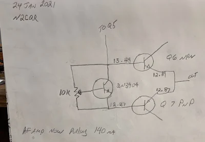
This morning I built the circuit on a small piece of PC board.  There were just two components: a 10k trimmer pot and a 2N3904 transistor.  

With the little board installed, I adjusted the pot for a 1.2 volt difference between the bases of Q6 and Q7. I ended up with base voltage values almost identical to those called for in the KLH schematic. 

The receiver sounds very nice now, and is no longer on the verge of bursting into flames.  I even made up my own version of the pillow that KLH claimed was necessary for proper acoustic suspension.  

Sometimes it is nice to be able to listen to something other than the chatter on the ham bands. And it is fun to do so with a receiver that you have worked on.  

I even used some Desitin as a substitute for heat sink compound. 

Thanks to Rogier for the receiver, to ZL2DEX, K0EET, W2AEW and David McNeill for the good advice. And to Dale K9NN who sent me a box of parts from which emerged the 10k pot I used in this project.  Thanks guys. 73  

Thursday, December 10, 2020

Pete Juliano's Presentation to the 2020 G-QRP Club Convention -- Building SSB Transceivers


It is a great day my friends.  G-QRP has posted on YouTube the presentations made at their 2020 convention. TRGHS! Above you can see the awesome FB contribution of Pete Juliano N6QW.  I watched it live on Zoom, but have been waiting patiently for the opportunity to share it with SolderSmoke readers and listeners. 

There are many other great videos of convention presentations on the G-QRP YouTube channel.  Here is the link to the channel: 
Be sure to subscribe and give many "thumbs up" to the presentations. 

I see that our friend Alan Wolke W2AEW has a presentation on the NanoVNA in that channel. FB Alan. 

Thanks to G-QRP for running this event and for putting these videos on YouTube. 

Tuesday, September 8, 2020

Builds Oscilloscope at age 12! Nick has THE KNACK


Thanks to Grayson Evans for sending us this very encouraging video.  
It is from Tektronix;  I wonder if Alan W2AEW provided some ideas and inspiration? 

More stories like this:  https://www.tek.com/stories  

Sunday, July 26, 2020

Alan Wolke W2AEW on IMD, NanoVNA and more (presentation to UK club)


This video is another reminder of how lucky we are to have Alan Wolke W2AEW as a fellow radio amateur, and as a teacher and mentor. 

In this video, Alan is talking to the Denby Dale Amateur Radio Society in Yorkshire, UK. 

The first part of his talk is about IMD products, the importance of 3rd order products, and the benefits of attenuation. 

The second part of the talk (after a few questions) is a look at the NanoVNA, which Alan cites as the "Toy or Tool of the Year."   

I learned a lot from both portions of the presentation.  I now find myself wanting an H4 model of the NanoVNA (bigger screen).  Or maybe even an F model.   Thanks to Alan, I now know what S21 and S11 means. 

Thank you Alan, and thanks to the Denby Dale ARS.  

73  Bill 
  

Wednesday, June 10, 2020

Alan Wolke W2AEW Explains the Vector Network Analyzer (VNA) (Video)


I told Alan that his video on VNAs was -- for me -- very timely.  The video popped up on YouTube on the day than my NanoVNA was being delivered.  TRGHS. 

Alan does a great job in explaining what the VNA does.  Particularly useful for me was his explanation of the VNA's ability to measure phase differences (through the use of directional couplers).  

I am having fun with my NanoVNA, happily measuring SWR and the bandpass characteristics of various filters.  Mine came with what looks like a guitar pick -- this is used as a stylus to hit the small boxes on the touch-screen.  A nice touch...   

I wish there was some good software for use with this VNA.  Apparently the nice software described by Joe Smith (yesterday's blog post) is quite expensive.  Is there a free alternative out there? 

Thursday, June 4, 2020

No Main-Tuning Reduction Drives in Stock Drake 2-Bs -- But why no mod articles?


Alan Wolke W2AEW and I were recently discussing our Drake 2-Bs (again!). Both of our receivers have reduction drives between the main tuning control and the string mechanism that moves the main tuning capacitor.  I wondered if these were the results of modifications by previous 2-B owners.  I vaguely recall that my Elmer -- Hilmar WB2NEC -- had done this sort of mod. 

OM Wouter ZS1KE sent me this very illuminating photo of the inside of his Drake 2-B.  No reduction drive.   So Alan and I obviously have modified 2-Bs.

One thing that puzzles me:  I can't seem to find a single article that describes this apparently common mod.  Does anyone know of an article in the ham magazines that might have described how to do this?  

Thanks again Wouter!  


Saturday, February 29, 2020

How to Measure Output Impedance (video)


Thanks to Tony Fishpool G4WIF for alerting us to this very useful video by Alan Wolke W2AEW. 

Alan's video channel is a real treasure-trove for homebrewers.  

It was very cool to see "AEW" inscribed on the function generator that Alan built 30 years ago. 

Be sure to stay to the end of this video for some electronics humor from Alan.  (Steve Silverman:  Take note -- we might want to add this to the lexicon.) 

Now I'm going to search Alan's YouTube channel for a video on how to measure input impedance. 

Sunday, May 26, 2019

DIY Waterfall -- A Quick and Easy Panadaptor Using a Sig Gen and O'scope (video)


I've been getting waterfall envy.  The panoramic frequency display is the one thing that could lure me to the dark side (SDR).   Heck, they now have 3D waterfalls!  What next?  Holographic waterfalls? Virtual reality waterfalls?  This is almost too much. 

Anyway, in an effort to counteract all of this waterfall seduction and to show that us analog HDR guys can go panoramic too, I decided to try to create my own panoramic display without resort to SDR.  

Of course, this is a very old technique.  It was invented in the 1930s by Marcel Wallace, F3HM.  He was the inventor of the Panadaptor which was the forerunner of today's waterfall.  Panoramic reception was used by the armed forces during WWII.  In 1946 Hallicrafters marketed a Panadaptor for its ham radio receivers (see below). 

In figuring out how to do this, I thought back to my use of my Feeltech signal generator to scan the response of a crystal filter.  The Feeltech has a very handy sweep feature.  

In this case I set up the Feeltech to sweep from 4.85 MHz to 4.75 MHz in one second.   With the 12 MHz IF of the BITX40 module, this would result in a sweep from 7.150 to 7.250 MHz. 

The sweeping Feeltech just replaced the VFO on my BITX.   I hooked up the Rigol oscilloscope to the audio output of the BITX.  I set the horizontal scan rate at 100 ms per cm.  This would have the trace go across the whole screen in 1.2 seconds. 

After a bit of fiddling, I could see signals on the 40 meter phone band.  But my display would kind of drift along the screen making it hard to know the frequency of the signals I was seeing. 

Alan Wolke W2AEW provided the solution.   He advised me to put a big stable signal at 7.150 MHz near the input of the BITX, then use this strong signal to trigger the 'scope scan.  The HP8640B signal generator that Steve Silverman gave me (and that Dave W2DAB picked up for me in NYC) provided the triggering signal.  

I put a piece of tape across the bottom of the scope display to calibrate the display.  See video above. 

It works!   It is not as cool as the SDR waterfalls, and it does not convey nearly as much information, but it was a fun project. 


Tuesday, January 8, 2019

Old Station On-The-Air -- A Transmitter Half as Old as Radio Itself

I'm biased, but I think it is "a thing of beauty."   With some unexpected free time available, today I followed up on my HT-37 work by cleaning and aligning the Drake 2B.  I was assisted in this by one of the many great YouTube videos by Alan Wolke W2AEW.   

The Drake 2B's 50 kc and 405 kc oscillators were right were they were supposed to be -- no adjustment required.  And I don't think they have been peaked since 1973.  The 455 kc IF can was also very close to perfectly tuned. 

Since most stations from the mid-1960s had some QSL cards on the wall behind the rig, I pulled out some old ones and put them up.  Many of these contacts were made by the rigs in the picture. 

If we say that 1897 marked the first use of radio, and if we assume that this HT-37 was manufactured in 1959,  that means that my old transmitter has been in operation for almost HALF of the history of radio.  

Tuesday, May 30, 2017

Farhan gives me a Spectrum Analyzer and W2AEW Provides the Tutorial (Video)


At Dayton, Farhan very kindly bought me a Tektronix Spectrum Analyzer.  (I joked during his visit that this device might help me stay in the good graces of the FCC.)   This morning I decided to learn more about this device.   I Googled "Tek 1401A" and was immediately directed to a YouTube tutorial.  I was pleased to see that it was from our old friend Alan Wolke W2AEW.  I knew that the Tek analyzer and I were in good hands. TRGHS.  Alan expertly laid out the functions of the device.  I am confident that I will soon be analyzing the spectrum of my homebrew rigs, and that they will all be found COMPLETELY FREE of spurious emissions.

Alan's tutorial is instructive for all those getting started with spectrum analyzers. 

I need to find a manual and schematic for the 1410A.

Thanks Farhan.   Thanks Alan.   And three cheers for Beaverton, Oregon!

Designer: Douglas Bowman | Dimodifikasi oleh Abdul Munir Original Posting Rounders 3 Column