Podcasting since 2005! Listen to Latest SolderSmoke

Showing posts with label DDS. Show all posts

Wednesday, April 1, 2020

SolderSmoke Podcast #220 -- S-38Es, AD9833s, Pete's Phasing Rig, FT-8

Java on the S-38E Tuning Dial
SolderSmoke Podcast #220 is available


Hunkered Down.  StayInTheShack:  SITS!  Flatten the Curve!  It is working.
Teaching English again – via Zoom.  Kids completing the school year remotely.  

BILL'S BENCH

-- Finishing up on the S-38Es.
  
-- I wrote up my alignment, isolation and dial string experiences.

-- SWL  WRMI Radio Miami International on 39 meters 9.4-9.9 MHz.  Rock and Roll.

-- S-38E work is causing me some serious legal problems.  They are threatening to take down our sites and our podcast.   Google has put a CEASE AND DESIST ORDER on my blog:   Check it out http://soldersmoke.com/CEASEANDDESIST.JPG

--S-38E caused me to want to get my HRO dial receiver on the SW broadcast bands with a good AM detector.  

-- Next up: Hayseed Hamfest cap for my Drake 2-B.  And I have an idea on how to easily broaden it for AM:  Tap the 455 kc output on the Q multiplier jack.  455 AM detector to audio amp. 

SHAMELESS COMMERCE DIVISION

PETE’S BENCH

AD9833

Phasing Rig Project
.
DEAN’S PROJECT – Step by step.  Trouble shooting.  Understanding.  Receiver triumph.  FB.

MAILBAG

Jack 5B/AI4SV doing well in Cyprus
Daniel SA7DER listens during commute in Sweeden.
Peter VK2EMU building a 6 meter amp.  With Tubes
Jim WA8ZHN  says there are still 7751 Novices on the books.   FB.

Mike WB2BLJ modding his BITX – having a lot of fun.
Fred KC5RT – Great idea on isolation transformer in my S-38E.  
Jerry Palsson: S-38C's curves vs. S-38E's exotic places.  Java. 

Anonymous mail:  FT-8 DX -- Are these contacts legitimate? See below. 


Dear Bill and Pete: 

I've been meaning to share with you something that has come to my attention by a rather circuitous route. 

As you guys know, I've been involved in the software/IT side of ham radio for many years. I've watched many digital modes come and go.  I've always enjoyed my work, but lately I've seen something that makes me uneasy. 

I'm sure you guys have heard of the fantastic DX that is being worked by many guys using FT-8.  It seems like all they need to work Jakarta is a couple of watts to a wet noodle. Shazam!  Contact! 

Well, I learned something that calls into some question the legitimacy of many of these contacts....  

As i understand it, certain manufacturers, in cahoots with a major American ham radio organization (that happens to be very dependent on ad revenue from that manufacturer), have secretly set up a system that combines the internet and ham radio. 

Here is how it works:  Suppose Joe Ham gets on FT-8 on 40 meters.  He puts out a call using his QRP transmitter and the aforementioned wet noodle.  No way that signal is going to Jakarta, right?  Well, it will with a bit of help.  

The system has SDR transceivers  and great antennas set up at strategic points around the world -- these are really great locations -- think mountain tops near the coastlines, always with high speed internet T5 connections. I think this is part of the whole “contest superstation for on-line lease” business model.  
One of these stations picks up Joe Ham's FT-8 call. Sometimes it will just re-transmit it, sometimes is will send it to a counterpart station on the other side of the globe.  Bingo, Joe Ham's signal is suddenly in Jakarta.  A station there enthusiastically responds, and that signal goes back with the same kind of repeater/ internet assist.  This is all done out of the reach of the FCC.  They are usig overseas locations,  some of them in Mexico.

Of course they have to be careful not to "facilitate" these kinds of contacts during times in which the bands are obviously dead,  That's why 40 is so useful for this system.  Obviously they can't keep this kind of thing secret forever -- they just want to get guys hooked on FT-8, then they can reveal the system, selling it as nothing unusual, you know, sort of akin to Echolink.  

Of course, this hasn't been made public (for obvious reasons!) but I can tell you the name of the system:   They tried to make it sound like something familiar (in this case like APRS): They call it  "Automatic Private Radio Internet Link 1."  My understanding is that when they do their “roll out” they will offer the new service to those willing to pay a subscription.

Obviously as an old-school, traditional ham, I'm troubled by all this.  What do you guys think?  I wonder what your listeners would think. 

Please don't mention my name..  But here is a site that describes the new system: 

Thanks and 73... 


Please let us know if you have any information on this, or have observed any unusual and suspicious success with FT-8.


Friday, October 26, 2018

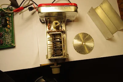
Homebrewing Your Own Variable Capacitors


It is people like Jeremy Cook who will save us from total domination by DDS and PLL "oscillators" and their whimpy little "rotary encoders."   

Saturday, April 29, 2017

How LCD Displays Work (Video)


8 Bit Guy does a great job de-mystifying the LCD displays that we have been using.

Monday, March 27, 2017

A Slovakian Al-Fresco Digi-Tia Homebrewed In France (and an improved AD9850 VFO)

Hello Bill and Pete,

Thanks for the podcast! My normal occupation is more computers and
software but your podcast got me motivated to melt some solder. So I
want to share a bit of what has been cooking on my bench.


I used to have a Yaesu FT-450 but sold it - I am living in a tiny rental
apartment in France without any place where to put a proper antenna so
it was only collecting dust. And where is the fun in operating a
factory-made rig, right?


So I have been working on this instead:

http://janoc.rd-h.com/archives/541

This "al fresco" rig is "half-DigiTIA". Half because there is no
transmitter part (I don't have a French license and I am too lazy to do
the paperwork and convert my Slovak one).  The purple modules are TIAs,
as designed by Wes Hayward, using 3x 2n3904s, only built using SMD
components to keep them small and tidy.


VFO & BFO are Si5351 + ATMega328, with an OLED module and code adapted
from Pete N6QW. It uses 11.997450 MHz IF because that's where most of my

12MHz crystals actually matched.

The 40m bandpass filter is taken verbatim from the BitX 40 design - I
have only changed the coils to use toroids instead.


For audio I have used LM386 with a NE5532 opamp as a low noise preamp
because the audio was a bit low. The TIAs don't have a lot of gain and I
have only an indoor magnetic loop for antenna so had to compensate for it.

I have another, a bit older project that became quite popular - firmware
for the AD9850 DDS VFOs using an Arduino and a character LCD. It is a
much improved replacement for the one from Richard, AD7C.


http://janoc.rd-h.com/archives/502

Perhaps it could be useful to someone.

Keep up the good work and 73!

Jan OM2ATC (at the moment "in exile" in France)


Sunday, March 12, 2017

KC1FSZ's Peppermint Bark BITX: Aeronautical Mobile for his FIRST QSO. TRGHS.


Bill and Pete:

Can’t say enough good things about your podcast - thanks for all that you do.  I’m a fairly new ham and have been trying to go the home-brew route as much as possible.  

I bought a BITX40 module (pre Raduino vintage) and added my own VFO board using the usual parts.  Actually, I’m using a Teensy 3.2 instead of an Arduino because it is a faster part and has a lot of DSP functions built into it that I’m using for digital mode stuff.   But it’s the same basic idea.  

My BITX40 is not as photogenic as some of the others, but I sent a picture below. This is the “biscuit tin” variety.  It’s was funny actually: a co-worker of mine stopped by my office around Christmas to give me a gift and pulled out of his bag a very nice box of “peppermint bark” candies with a ribbon around it.  The VERY FIRST thing that crossed my mind the instant I saw the gift was …. BITX40 ENCLOSURE!  He must have been pleased to see the huge smile that came across my face. :-)   I’ve been bitten by the bug for sure.  

My first three HF QSOs (ever) where on the BITX and were all very interesting:

  • First real QSO of my life was with KE4TJB “air-born mobile” off Delaware.  He is a commercial pilot flying for JetBlue and apparently has time to work QRP stations during flights??  I wonder who was flying the plane?
  • Then I was scanning around this morning and caught K4HW making last calls for check-ins on a net running on 7242 out of North Carolina.  I decided to give it a shot, having never joined an HF net and I was recognized!  As the first round got going I realized I had joined a Jehovah’s Witnesses net.  They were very friendly and the net control stopped to help my get my frequency calibrated before they continued with the scripture passage for the week.
  • Later this morning I reached K3KLC in Maryland who had the high-end SDR rig with the waterfall/panadaptor/etc.  Remembering comments that you guys have made about these types of folks on 40m, I was very concerned.  But this guy turned out to be very helpful and sent me some screen shots showing what my signal looks like.  

Thanks again, and 73s,
Bruce MacKinnon
KC1FSZ
Wellesley, MA


Thursday, January 12, 2017

N6ORS's Franken-SDR Superhet


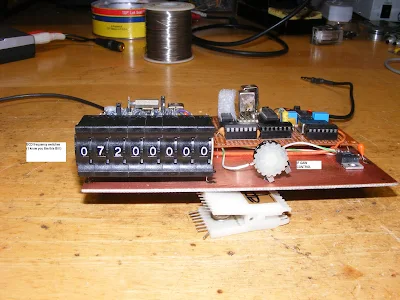
Of course, I love it.  MOSFETS!  NE602's!  10.7 Mc IF cans!  Cycles, not hertz! And a Tayloe Quadrature Sampling Detector made from junkbox parts from the Reagan administration. FB Keith.   And the frequency display is icing on the cake.  

Bill:

I thought the group might find my new Franken-SDR interesting.
It is an SDR with a superhet front end. 


I wanted to play with an SDR but I didn't want to get a kit or buy
parts, so I scrounged through he drawers and found a mux chip
cd-4016 circa-1980 some old 7400 logic that is probably per-1980.
This could make a QSD but only very low frequencies. Well I thought
how about at IF frequencies?


The frontend is a MOSFET mixer (1975) , the 10.7 IF is a dual gate MOSFET
(1975), the second mixer is a NE602, the IF cans are all stagger tuned to
give a bandwidth of 50kcs.
The only thing modern is the DDS but I old-time-ifyed it with BCD switches.


Keith N6ORS


VK6FTH did something similar: http://www.vk6fh.com/vk6fh/SDRradio.htm


Tuesday, January 10, 2017

Understanding the "O" (organic) in OLED


That's the one I'm using.  Less than 1 inch on each side.  No back light.  8 bucks shipped:
https://www.amazon.com/gp/product/B00KRZY7PW/ref=oh_aui_detailpage_o07_s00?ie=UTF8&psc=1

Here is a thorough description of the technology:

https://en.wikipedia.org/wiki/OLED

Tuesday, December 27, 2016

From Mountaineer to the KX1 -- N6KR on Trail-Friendly Rigs


This is from 2014, but I stumbled upon Wayne Burdick's article just this morning.  Great stuff.  That picture of Wes had a big impact on many of us. 

Wayne's article:

http://www.elecraft.com/KX1/N6KR_KX1_History.html

Wednesday, December 21, 2016

Armstrong, obsessed


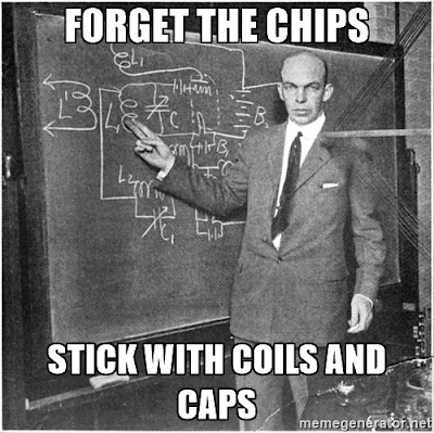
Jerry AA6KI sent me a nice website about radio hero E. Howard Armstrong. It contained an image that seemed to cry out for a meme.  I couldn't resist.

Monday, October 31, 2016

Hacking the Hackable BITX 40 Module: VFO is the Way to Go!


I am having a lot of fun with Farhan's new BITX 40 Module.  I think I'm doing exactly what Farhan intended people to do with this rig:  work on it, modify it, improve it. 

I've been working on frequency stability.  I was, I admit, skeptical from the start about the stability of a  thumb-sized,  SMD, varactor-tuned VFO with a ferrite or iron powder toroidal coil.  Don't get me wrong -- it worked.  But it drifted. It seems to me that it would be asking too much to expect a VFO like this to be drift-free. (But I may be wrong -- are there any SMD, varactor-tuned VFOs out there that DON'T drift?)

First I thought it might be the 9 uH metallic core toroid.  So I replaced that with a 10uH choke -- no ferrite or iron powder in there.  That seemed to help a bit, but SSB QSOs would still quickly drift into Donald Duck chatter.  Then I thought it might be the varactor diode.  I let it warm up.  A lot.  Still, it drifted.  Then I thought it might be the trimmer cap, so I took it off the board.  No change.  During this process I noticed that even slight pressure on the board caused the rig to shift frequency.  I began to suspect that the drift was just structural -- a consequence of the physical characteristics of the SMD parts and the board.  To get VFOs stable I've had to build them big:  10 X 10pf  NP0 caps to make one 100 pf cap, large air-core coils, and big sturdy variable caps.  I'd isolate the frequency determining elements in a box separate from the powered components. This little VFO just looked too small to be stable.   

So faced with drift, at first I asked myself,  "What would Pete do?" I took an AD9850/Arduino combination off the shelf and plugged the output into the "DDS" jack Farhan had placed on the board.  I removed the 10uH choke.  Viola! With the DDS tuned to 4.7 - 5 MHz, the receiver worked great.  I briefly tried to updated the Arduino code to take into account the 12 MHz IF (so I could get an accurate frequency readout), but ran into the old painful Arduino IDE problems:  Now it is claiming there are library problems.  Not wanting to suffer through another round of digi-agony, I left well-enough alone.   I used the DDS with the old code for one day. 

But of course, I was not satisfied.  Attaching a DDS or PLL synthesizer to the BITX 40 Module just didn't seem right. Heck, it was kind of like just hooking up my FeelTech Chinese sig gen to the DDS jack.  Farhan's rig is simple, beautiful and ANALOG.  The parts are small, but you can see them.  You can put your scope probe on the collector of Q7 and see what is going on.  DDS or PLL.  It is a REAL HARDWARE-DEFINED RIG.  So I decided to build a VFO.   Pete calls VFO's "grief machines"  but for me, the grief machines are those little Arduino beasts.  To each his own.

When I build a VFO, I start with the variable capacitor and the reduction drive.  I found a nice one (with reduction drive) in my junk box. I tunes from 40 pf to 56 pf.   I decided to use the super-simple Hartley circuit presented by Wes Hayward W7ZOI in SSDRA (page 34, fig 7). 


I went with a 4.4 uH air core coil (wound on a cardboard tube from a coat hanger).  Consultation with on-line resonant frequency calculators showed that I'd need to put about 180 pf in parallel with the variable cap.  For this, I used a bunch (maybe 10?) of small value  NP0 caps in parallel.  This really helps keep the VFO stable.

As I did with my HROish receiver, I put the coil and the caps in one box, with the MPF-102 and associated parts in an  attached Altoids tin.  Everything was glued and bolted down very solidly.


I only built the actual oscillator stage -- I decided to use the buffer amps on Farhan's board.

The oscillator started right up.  I had to add and then take away some turns on the coil to get it to run in the desired range.  Then I plugged it into the DDS jack -- the receiver was working immediately.

I noticed, however, that it seemed a bit less sensitive than it had been with the AD9850 DDS. And when I grabbed the wire going into the DDS connector, audio output jumped dramatically.  It took me a few minutes to figure that out:  I think the output from my VFO was not adequately turning on the diodes in the diode ring.  When I grabbed the wire, I was putting a lot of noise into the mixer port, probably turning the diodes more fully on (but also letting a lot of noise through).

Fixing this problem part was fun:   Looking at the BITX 40 schematic, I saw that the two 1000pf feedback caps in the original oscillator were still in the circuit.  I figured those caps would be sending a lot of my VFO energy to ground.  So I fired up my hot air rework station and deftly removed C91, the 1000 pf cap that is connected to the base of  Q9.   Instantly the receiver started inhaling as it had with the DDS VFO.  That was a very satisfying fix.

This whole VFO project was very satisfying.  It was all done in one day, and all the parts came out of my junk box. I think I ended up with an LO frequency source that matches up in a pleasing way with the analog circuitry in Farhan's rig.  And here is bonus that I think is just what Farhan had in mind:  this kind of circuit adds a definite homebrew element to the module rig.   

I found that this external VFO improved stability significantly.  I don't know if it is as stable as the DDS, but with the external VFO the receiver no longer drifts away as I listen to SSB signals. 

Sunday, October 2, 2016

GW4ZUA's "Let's Build Something" Receiver


The LBS project of Pete and Ben continues to inspire homebrewers all around the world.  Check out the video of GW4ZUA's version.  Peter GW4ZUA writes:

Hi Pete,

Thank you for your kind words,

I suppose it started with a knob and a pointer to know (guess) where you were on the band, probably most radio builders did the same, and some still do, but as long as it worked you were very satisfied, what a marvelous feeling when you switch on and those electronic components do their job and deliver the goods......amazing.

So time moves on you get better at building and technology gives you a hand, LCD displays, homebrew frequency counters,cheap components, wow now you Know where you are on the band.

Then I saw your rig with a colour display and DDS "I gotta get me one of these."

I watched most of your videos, Your "easy going, down to earth manner" made it look easy to do.
I love the internet, without it I'd probably still be using knobs and pointers, there are is a wealth of knowledge available to those lucky enough to have access. I also love email, as you can now contact people who are willing to share their projects and give advice.

So the LBS well it certainly works, so few parts but they are all eager to please, with the display (did I mention the display) it is a project you can be proud of.

A big thank you to you and Ben for the project,

I don't know if it will ever go in a box as I just love to look at it and I'm amazed at what comes out of the speaker.

Regards to you all..........
73's for now.  ...........Peter (GW4ZUA)
------------------------

As is well known, I'm more of a knob and pointer guy myself, but I understand the attractions and advantages of the glowing numerals.  And I definitely sympathize with Peter's comment about the beauty of an in-boxed rig.


Friday, February 12, 2016

A Snow Day Well-Spent: Chris Modulates an AD9850

Feb 10 at 7:40 AM
Hi Bill and Pete,
My work is closed today due to the snow so I wanted to show you what I've been up to.
I built sort of a test fixture a while back for those cheapie EBay AD9850 boards based on AD7C's DDS circuit using an Arduino Uno as a controller.
Last summer someone posted a link to Analog Devices App note AN-423 on QRP-Tech I think.
It was always on my list of things to try.
Armed with a schematic of the eBay DDS gleaned from Doug Pongrance's website, I got to work. It involved cutting a trace or two on the DDS board using an X-Acto knife.
Two outputs of the DDS chip are fed into a wideband transformer as in the app note's second page and I hung a scope probe off the secondary of the transformer.
Basically you are removing the Rset resistor on the DDS board (marked R6 on mine) and using a 2N7000 MOSFET as an electronic version variable resistor and modulating the MOSFET.
This lead to much frustration over the afternoon. No output on the scope!! Did I make an error or connect something up wrong? I was using the 600 ohm output of my HP652A audio generator. I thought about it during lunch and decided to try the 50 ohm output. Bingo!! At the 3V RMS range setting on the generator I now have some kind of signal. Not a nice sine wave shaped AM output but at least something resembling a clipped sine wave. The circuit is really touchy as far as needing a hefty audio signal in. The output of my iPhone at max volume doesn't turn on the DDS chip.
I set the DDS for 1200 kHz and can listen to it on a Radio Shack portable radio. Varying the audio generator varies the received tone on the radio just like I was expecting.
I just need to figure out what's up with the audio levels.
Chris
KD4PBJ

Tuesday, February 9, 2016

Back to Divide by 4 -- Big Improvement in Receiver Performance

Thanks for all the comments and advice.  I have come to understand the wisdom of divide by 4 IQ circuits.  

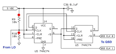
Fortunately it was very easy to convert the divide by two 74AC74 circuit described earlier to a version of the divide by 4 scheme seen above.  (From the SDR Ensemble II Receiver:  http://www.wb5rvz.com/sdr/ensemble_rx_ii_vhf/04_div.htm)

This change provided a great way to observe 1) the improvement in the output signals from the VFO and 2) the resulting improvement in receiver performance, especially opposite sideband rejection.

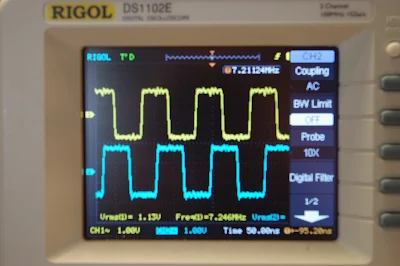
Here are some numbers. I was very pleased to discover that my Rigol scope will measure duty cycle and phase difference. Thanks Rigol!

AD9850 Divide by 4 :  7.212 MHz  Duty cycle: 48.3  Phase Difference:  87-90 degrees

Si5351 Divide by 2:      7.212 MHz  Duty Cycle 49.6  Phase Difference:   83 degrees

Si5351 Divide by 4       7.212 MHz   Duty cycle 49     Phase Difference:  85-90 degrees

Additional improvement came when I switched the power supply to the IQ inverters and Flip Flops.  I switched from 3.3 to 5 volts:

Si5351 Divide by 4       7.105 MHz   Duty Cycle 49.7    Phase Difference:    90 degrees

When I took the VFO box and put it back in the receiver with the divide by 4 scheme and the 5 volt supply I immediately noticed a big difference in performance.  It was obvious that opposite sideband rejection was back to what I had had with the AD9850, perhaps better. 

I have a quick and dirty method of measuring opposite sideband rejection: I put an RF signal into the antenna connector.  I put the 'scope on the audio output.  I tune (on the desired sideband) for 1kHz audio and I measure the output voltage.  Then, with the audio gain and RF sig gen output in the same positions, I tune to the opposite sideband, again tuning for 1 kHz, again measuring audio output.  With the divide by 4 scheme and the 5 volt supply, the opposite sideband was so weak I had trouble measuring it.  I estimate the rejection to be at least 32 db -- this is back in the range of what I had with the AD9850, and significantly better than I had with the divide by 2 scheme. 

Now I just need to figure out how to get the Si5351 VFO sketch to tune above 42.94 MHz.  For some reason it quits at this point, switching down to 2 kHz output, and keeping me on 30 meters and below.

Thanks again to Todd VE7BPO for a lot of help with the hardware and to Tom AK2B for help with the Arduino code.  
   

Sunday, February 7, 2016

Ambition, Greed, and Experiments with a Divide by 2 IQ VFO

Fresh from a great success with the use of the M0XPD divide by 4 I and Q VFO in my Frankenstein Phasing Receiver, I got ambitious.  And greedy.  I wanted more.  More frequency coverage.  More bands.  Divide by 4 can really limit your frequency range.  The AD9850 only goes up to 40 MHz.  Divide by 4 and you can't even get the 30 meter band. 

So I started looking at other options.  Si570 looked nice, but here the lower limit was the problem: 10 MHz.   Even with divide by 4,  that knocks out 160 meters, a band I am very interested in lately, and that seems to sound especially good in a direct conversion receiver.

Once again, the controversial Si5351 was calling my name.  It would go down to 8 kHz and up to 160 Mhz.  Woo Hoo!  If I could build a divide by 2 IQ VFO, I could cover 160-6 meters.   

Here is the basic idea.  From:
http://www.markimicrowave.com/blog/2015/04/top-7-ways-to-create-a-quadrature-90-phase-shift/

 The Flip Flops are set up to change state when the input signal is going up.   By putting an inverter at the input of the bottom FF input, in effect you have that one changing state when the input signal is going down.  Look at this for a minute or so.  Look at the square waves at the bottom.  See it?  See how it takes an ordinary signal and spits out two signals, one 90 degrees off the other?  Pretty cool, don't you think?

With lots of hardware help from Todd VE7BPO, and software help from Tom AK2B (wizards both), I got my Si5351 divide by 2 circuit working today.  You can see the resulting I and Q in the picture at the top.   But I am discovering that there may have been wisdom  behind those divide by 4 circuits.  My opposite sideband suppression isn't as good with this /2 scheme as it was with the AD9850 divide by 4.  I'm still trying to figure out why. I may have to go back to divide by 4.  Stay tuned.    


Wednesday, February 3, 2016

New VFO for the Frankenstein R2 Phasing Receiver


I've wanted to change the VFO in my R2 phasing receiver.  The AD9850 DDS VFO with a divide by 4  I-Q generator limited me to 160, 80 and 40 meters.  But an Si5351 chip will go up to 160 MHz.  With a divide by 2 I-Q generator, this should allow me to cover 160 through 6 meters. I got the Arduino, LCD and rotary encoder all working tonight.  Thanks to Thomas LA3PNA for the code, and to Tom AK2B for help with the Arduino. The Si5351 board that you see sitting atop the Arduino is the work of Dean AC9JQ.  Thanks Dean.  

The flip-flop and inverter IC's should arrive this week.  That will allow me to finish up this VFO conversion project.

Tuesday, January 19, 2016

Arduino Problems -- Back from the Ledge

As I was struggling through this, someone -- who will remain nameless -- told me that because of all the technical problems resulting from the many Arduino IDE "upgrades," suicide prevention hotlines now answer all calls with an automated question:  "If you are calling about an Arduino problem, press 1 for assistance."

It got pretty ugly but with the help of Tom up in NYC I managed to get through it. First he convinced me that it is indeed POSSIBLE to upload the latest version of the IDE -- the dreaded 1.6.7.   I just had to REALLY get rid of earlier versions.  This got me past the horrible Bundled Java Runtime Environment problem (who thinks up these names?).

We then worked with the libraries needed to upload the AD9850 code of Richard AD7C.  You see, I work on Arduino stuff.   Then I stop.  18 months pass.  I forget all I learned.  Then I start over.  The pain begins again.  In an effort to break this cycle, I am now taking notes (in the inside cover of Mario Banzi's book).

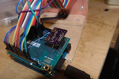
I am using the AD9850 with a Kanga Arduino shield designed by Paul M0XPD.   It takes the AD9850 output, divides by 4 and puts it out as 2 square waves in quadrature.  I use this with my R2 phasing receiver.   The problem was that the display on the Arduino showed a freq 4 times the actual tuning freq.  Believe me, this gets old fast.  I considered just getting a San Jian freq counter and supergluing it on the top of the DDS box.  I was going to connect this to the square wave output.  That would have given me one readout with the actual receive freq, and another (on the Arduino) showing the (4X) freq coming out of the AD9850.  But that would have been too much of a Kludge. Tom talked me out of it and modified the code so that the Arduino display shows the actual receive freq.   Thanks Tom.  

Armed with the new IDE and with my knowledge of Arduino basics refreshed, I was able to reload the LA3PNA Si5351 code into my 40 meter DIGI-TIA.  But not before having to swap out the Arduino that drives the Si5351.   One Arduino happily accepted the code, another did not.  Why?  Who knows?  It is a digital mystery.  Those little 1s and 0s are fickle you know.

The Radio Gods rewarded me for all this.  At about 5:45 AM today I was listening to a very friendly SSB roundtable on 160.  The guys were getting ready to sign off.  The last one ended the conversation by asking the others to "Be kind.  Smile at your neighbors."  Nice.
Then WFAX AM started the broadcast day at 6 am, wiping out my 160 meter reception.  Next project:  High-Pass filter at 1.7 MHz.


Saturday, January 9, 2016

A Good Radio Morning at N2CQR


The Radio Gods were smiling upon me this morning.  I started out on 17 meters and had three nice contacts with European stations:  OH5CZ, a young fellow near Helsinki;  HB8DQL; then RM2D in Moscow. FB.

Then Pete showed up on the Skype. As he has said on his blog, he is still struggling with a family medical emergency, but I am happy to report that he is coping well, making good use of his can-do project manager background and his good sense of humor.  It was great to see him.

Inspired by my talk with Pete, with 40 meter AM playing in the background, I turned to my R2 FRANKENSTEIN phasing receiver.  Last night I completed the 90 degree phase shift network.  This is built around two quad op-amp chips and is designed to take the audio output from the two DC receivers and create a 90 degree phase difference between them.  I tested this stage by sending the same audio into each set of op amps.  I then put one scope probe in the output of one chain of op amps, and the other probe on the output on the other chain.  Wow.  Bingo.  90 degrees of phase shift across the 300 -- 3000 Hz audio spectrum. 

Emboldened by this positive result, I put the completed stages together this morning.  They passed the smoke test.  Then I tuned to 40 meters.   Wow again!  As promised, opposite sideband rejection without resort to crystal filters.  But as luck would have it, I ended up with a configuration that suppressed the Lower Sideband.  For 40 meters, obviously I needed to suppress the other side of zero beat.  But all I had to do to remedy this was to reach into the DDS box and switch the I and Q jumpers on the M0XPD/Kanga UK Arduino AD9850 shield.  This switch put me on LSB.  Very cool.

Here is a view from above:

The AD9850/Arduino DDS box is in the bottom center.  Above that, near the center of the picture,  is the board (from N6QW) with the two SBL-1 mixers and the initial AF amp stages.  The small green board above that is the IC phase shift network.  At the top of the picture you see the 3000 Hz low pass filter. Below that, the board with the little blue pot has an IC AF amplifier and a 300 HZ high pass filter.


I still have to build the audio amplifiers prescribed by the designer, Rick Campbell KK7B.   But obviously I am already having a lot of fun with phasing.  Here is the QST article on Rick Campbell's R2 receiver:
https://www.arrl.org/files/file/Technology/tis/info/pdf/9301032.pdf

Thursday, December 31, 2015

N8NM's Straight Key Night Rig


Hi Bill,
 
Just wanted to drop you a line to let you know that I’ve recently discovered your SolderSmoke podcasts and am enjoying the heck out of them!  In fact, you and Pete have inspired me to break away from the thermatrons and delve into the wonderful world of the TIA transceiver, and after several weeks of sniffing rosin, my new rig is now receiving signals without the aid of any external life support!  It’s still a bit haywired, but I’m looking forward to pairing it with my little 6AG76L6 transmitter for a few SKN QSOs tomorrow.
 
I haven’t taken any pics of the new rig yet, mainly because, at this point, there’s not much to see, but here’s it’s little octal-based friend with its AD9850/6AG7 hybrid VFO (works a bit better than the VF-1 that it replaced J):
  
Anyway, thanks for putting forth the time and effort to do the podcast!  All the best to you, Pete and your families in the new year.
 
73,
 
Steve Murphy, N8NM

Sunday, December 6, 2015

New Rig: The FRANKENSTEIN Phasing Receiver

Here is my latest project.  I call it The Frankenstein because of the two BNC connectors that come off the side of the DDS oscillator box -- they look to me like the bolts on Frankenstein's neck. The square waves from the DDS LO also seemed to evoke Frank's bolts. There may be other similarities.  We'll see.

Here is the idea:  Phasing,  Direct Conversion, Image Rejecting receiver based largely on the R2 design by Rick Campbell KK7B  as presented in the January 1993 QST.

I'm using an AD9850 with an M0XPD Kanga board and an Arduino to generate the quadrature LO signals (you can see the square waves on the 'scope in the background).  I'm using the software of Richard AD7C;  this, combined with the divide-by-4 scheme on the Kanga board,  puts the upper limit of reception at 7.3 MHz.  That's OK for now. 

When I first fired up my AD9850 box I was dismayed to find that the square wave quadrature output was no longer there.  I was about to give up and get anther shield board, but this kind of surrender bothered me.  So I started troubleshooting and isolated the problem to the /4 chips. My soldering of the surface mount chips was, well, a bit dodgy, so I changed to a tiny soldering tip and reheated all those tiny little pads.  Hooray!  I fixed it. 

The receiver will be built mostly on a PC board that Pete made for me back when he was trying to convince me to build a fourth BITX receiver.  I am pleased to put the board to use.   See below.

Yesterday I soldered on the two SBL-1 mixers that will form the heart of this receiver.   I realized that the very robust quadrature square waves from the Kanga board might be robust enough to fry the sensitive little SBL-1s.  Sure enough, I measured about 17 dbm coming out of the Kanga board.   I threw together two roughly 10 db resistive pads.  These should prevent the SBL-1s from releasing their smoke.     

I hope this receiver will be four receivers in one:

1) Standard DC receiver.

2) Binaural Receiver!  Groovy, stereo CW that floats around in your head,  man! 

3) I-Q receiver that can be fed into the sound card of the computer for DSP, panoramic display, etc.   I promise not use it to find fault with the signals of homebrew SSB rigs.

4) SSB image rejecting receiver for easy, Direct Conversion SSB listening without the burden of having to listen to the other side of zero beat. 

There is already a lot of soul in this new machine:  Kanga board with the design my Paul M0XPD, PC board made on Pete's $250,000 CNC machine, and all of it on an actual breadboard (from Italy, I think).  

Rick Campbell and Peter Parker have commented on the allure of phasing rigs.  There is something very attractive about them.  There is a cleverness in the way this design exploits the phase relationships between sidebands to allow us to null out the unwanted side of zero beat.  It took me a while to really understand how this is done -- once I understood it, I really wanted to build a rig that would make use of this principle.    


Monday, September 7, 2015

Si5351 and the Spectral Purity Mask


I was thinking about spectral purity standards and the Si5351 chip. I realized that I didn't even know what the FCC standards for "close in" noise are.   The standards for spurious emissions ARE well known, but these are for harmonics and parasitic emissions relatively far from the desired signal.  What about unwanted signals CLOSE to the desired signal? 

My old 2002 ARRL handbook indicates that the FCC has not established firm standards for this "close in" noise.  (They call it "out of band" noise, but are clearly referring to noise that is close to the desired signal but spreading out beyond the desired bandwidth.  Phase noise would be in their category.)

In the course of my Googling, I found the above spectral purity mask.   I don't know where it comes from, but I think it is the kind of graph that would be very useful to us as we evaluate the merits and shortcomings of various frequency synthesizers.  Would our DDS or PLL rigs fit in this mask?   I think an Si5351 rig WOULD.  According to KE5FX's measurements, at a mere 100 Hz from the center frequency, the Si5351 phase noise is already -90 db.

Does anyone have a similar mask showing current standards?

I still don't understand why so many folks believe that the Si570 is a useful part for homebrew rigs, but the Si5351 is not.  Look at the numbers:

Si570
Clifton Labs  measuring at 30 MHz carrier. At 10kHz from carrier:   -109.6 dbc/Hz
Silicon Labs web site (carrier freq not specified) At 10 kHz from carrier:  -116 dbc/Hz

Si5351
KE5FX measuring at 19.99 MHz. At 10kHz from carrier:  -127 dbc/Hz
Silicon Labs  measuring at 156.2 MHz. At 10 kHz from carrier   -112 dbc/Hz.

Can anyone out there explain the technical basis for the belief that the Si570 is a useful part while the Si5351 is not?   

It is important to keep things in perspective.  ALL of these noise numbers represent VERY small noise levels.   Let's keep is simple and assume a 100 watt carrier signal and a phase noise of -100 dbc/Hz.   That means the phase noise per hertz would be .00000001 watts.  That's watts/hertz.  How much "noise power" would that represent in a typical SSB passband?  Multiply by 2500 Hz and you get 25 microwatts.  That's really low noise levels. Not enough to worry about.  And as we've noted, we've happily used rigs with LC VFOs and crystal oscillators for all these years without every once measuring their phase noise.

Our book: "SolderSmoke -- Global Adventures in Wireless Electronics" http://soldersmoke.com/book.htm Our coffee mugs, T-Shirts, bumper stickers: http://www.cafepress.com/SolderSmoke Our Book Store: http://astore.amazon.com/contracross-20
Designer: Douglas Bowman | Dimodifikasi oleh Abdul Munir Original Posting Rounders 3 Column