Podcasting since 2005! Listen to Latest SolderSmoke

Showing posts with label DSB. Show all posts

Saturday, May 31, 2025

Not a Toy! K1OA Making Contacts with the SolderSmoke Direct Conversion Receiver and a KA4KXX Transmitter

This goes to prove what we have been saying all along:  this receiver is not a toy!  It is capable of operating as part of a real 2-way ham radio station. Hall of Fame member Scott K1OA has paired his receiver up with a Merry Christmas transmitter designed by Walter KA4KXX and has been making CW contacts with it (see above).  Walter supplied the crystal and many of the needed parts.  Scott has already worked WA9RNE, N4HAY and W3RJ, and has tried making contact with Walter but no luck yet. He has gotten RBN reports from Germany and New Zealand. All that with just 3 watts.

This is not the first time this receiver has been out to use.   I made one contact with it using a "Ten Minute" QRPp transmitter that I had intended only to use for test purposes: 

https://soldersmoke.blogspot.com/2023/02/first-qso-with-high-school-receiver-100.html 

HoF member Aaron ZL1AUN used his receiver with an SSB transmitter to make contact using his receiver:

https://soldersmoke.blogspot.com/2025/02/soldersmoke-direct-conversion-receiver_23.html  We understand Aaron's article about the receiver has been published in "Break-In" magazine -- we hope to get a copy (electronic would be fine!) 

And who can forget HoF member Nate KA1MUQ who turned his "frying pan"  direct conversion receiver into a double sideband transceiver and used it to make phone contact with Idaho from California: 

https://soldersmoke.blogspot.com/2025/03/nate-ka1muq-turns-his-frying-pan-dc.html 

If anyone is aware of other contacts made using this receiver, please let me know.  

Sunday, May 11, 2025

Peter Parker VK3YE finds a Homebrew Double Sideband Transceiver at an Australian Hamfest


Peter's detective work on the mystery box starts at around 13 minutes into this video.  He quickly found a balanced modulator and did not find a crystal filter.  This led him to correctly suspect a double sideband transceiver.  A look at the LP filter and the VFO led him to suspect a 160 meter rig.  Nice work Peter.  That's what it is:  a 160 meter DSB transceiver. 

I had a similar experience with a direct conversion receiver, but never with a full double sideband transciever.  Nice find.  Peter should try to bring that rig back to life, and he should try to find out who built it. 

The Solid State Basics book by DeMaw and Rusgrove looks good.  I hadn't seen that one, but I will get one. 

Thanks Peter! 

Sunday, March 9, 2025

Nate KA1MUQ Turns His Frying Pan DC Receiver into a Double Sideband Transceiver and Works Idaho from California


Wow, you can see the look of homebrew satisfaction as Nate works Idaho from California with his homebrew Double Sideband Transceiver.  It is a good thing that Nate got that frying pan into the shack before he was banned from the kitchen. 

Nate writes: 

I finally got my DCR to be a DSB transceiver.  I had a lot of trouble with transmitted RF getting back in to the VFO and causing distortion.   While I imagine I could have tried putting the VFO in metal box, I instead opted to move the VFO to a 4.7-5 MHz range and then mix that with a 12 MHz crystal oscillator.  Now the VFO is at a frequency unaffected by transmit RF.  This mixer and crystal oscillator are on the breadboard and from SSDRA.  The transmit amplifier chain was taken from Fahran's Daylight Again radio.   I just got a 570 mile contact on 5 watts - conditions are good.   If there is interest let me know and I'll share my schematic.

-------------------

I looked this morning and I have 100 DSB posts on the SolderSmoke blog.  There are lots of ideas there on how to homebrew for DSB, many of them from Cuba, many covering DSB rigs that I built in the Azores, and others that I used in the Dominican Republic.  Check it out: 

Thursday, February 27, 2025

Derek N9TD's SolderSmoke Direct Conversion Receiver -- With a Double Sideband Transmitter


Derek N9TD was another of the early builders of the Direct Conversion receiver; he has done really magnificent work.  He is an Electrical Engineer, and you can see in his work (and in the email below) the tension that exists between the desire for simplicity and the urge to improve.  In the above photo, for example, we see that Derek had already gone ahead with the installation of an RF gain control. We also see his use of a steel screw and an outboard coil in series with the PTO coil.  All of these mods are fine -- I have used all of them. We just advise newcomers to build the basic receiver first, then put in mods from there. 

Derek has gone the extra mile (many miles in fact) by building a Double Sideband transmitter to go along with his receiver.  We know many will want to do this.  Our advise remains:  Build the basic receiver first, get it working, then do the mods, perhaps culminating in the build (as Derek did) of a Double Sideband transmitter and the creation of a DC-DSB transceiver. 

Here is a video of just the receiver in action.  
Note that the DSB transmitter circuitry is on the board:     

And here is Derek demonstrating a phone contact with the resulting DC-DSB transceiver:  

Derek wrote: 

Bill, 

Let me introduce myself, I am a recent electrical engineering graduate from Purdue and a long-time listener of the podcast. I want to thank you and Pete for being one of the reasons I chose to pursue my degree in the first place. I'll admit that in the more difficult stretches of getting my degree, I often pulled out the podcast to be reminded of the fun that can be had with radio and electronics.

Until recently I had to hang my head low along with the majority of the other 'appliance operators' out there having never built anything with my two hands that can be used to pull signals out of the ether.

 I am no stranger to building projects, PCBs, and melting solder but I usually chose to either stick to the dreaded digital domain or focus on antennas, filters, and other ancillary equipment. The logic being that I like to have a "known good" radio for the shack and that I would focus on other equipment to supplement the radio. I still follow this logic when I want to contest and we all know that antennas are well worth the effort, I've just finally had enough of being an appliance operator and have your podcast to thank for the extra push. 

I had been following the original effort of the TJ DCRX with interest from the start and earmarked this project as one I would like to build based on its inherent simplicity and good performance. However, the demands of school and a recent (at the time) abortive attempt to build an AM superhet with an SA602 the year prior made me  (I got as far as feeling the joy of oscillation but regretfully petered out after that) put this one the backburner for about two years until December 2024.

By coincidence, I independently decided to start this project just before your show with the HRWB folks and the gauntlet being thrown down, which has spurred many to build this receiver. It has been great to see the extra coverage on the receiver, and the commentary has been very insightful for someone trying to build this for the first time and with as many of the "improvements" as possible. 

For better or for worse, I'm the type of guy who wants to understand the "why" behind all the design choices and, from there, try to incorporate as many lessons and improvements as possible to make the "best" version possible. I'm not saying I make the best version of anything, but it's just a quirk of the way I think and justify doing a project. It always has to be "this and some additional improvement;" otherwise, I would decide against doing it. 

Rambling aside, I ended up building the DCRX, adding the RF attenuator from N3FJZ's website, and incorporating the lessons you learned after experimenting with improving the tuning on the PTO. I added an external series inductor wound on a dowel rod and used a zinc-coated steel screw as opposed to brass. I found that this gave solid tuning performance across 40m and was easy enough to tune in CW or SSB signals (after 3D printing a large knob for the PTO bolt). Alan W2AEW's video on mixers was a great tutorial to use to verify that my mixer was mixing. With the radio assembled I was treated to the joy of hearing my receiver breathe in the sounds of 40m for the first time last weekend and even managed to copy some Croatian DX during last week's contest. As Farhan said to do, I have spent the last few days enjoying the receiver and figuring out its quirks before moving on to the next step. 

The only "issue" I have noticed is that I still get some AM breakthrough despite tuning in the bandpass filter. The problem is very noticeable if I accidentally put my finger on the wires going to the AF gain pot. If I do that the AM station is the only thing I can hear. This makes me think the problem is after the bandpass filter and more investigation is needed. Maybe using coax on the control lines to shield it will help? Regardless I am impressed with how well the receiver sounds, the stability of the oscillator, and the effectiveness of the simple audio amp....  

Again thank you and Pete for your work on the podcast and for helping inspire countless homebrew radio operators! 

73s,
 Derek N9TD

--------------------
Thanks Derek.  And thanks for helping other hams get the 3D printed PTO coil forms that they needed. 

For more information on how you too can build the receiver: 

Join the discussion - SolderSmoke Discord Server:

https://discord.gg/Fu6B7yGxx2


Documentation on Hackaday:

https://hackaday.io/project/190327-high-schoolers-build-a-radio-receiver


SolderSmoke YouTube channel:


Wednesday, February 26, 2025

Peter VK3TPM's SolderSmoke Direct Conversion Receiver (and his follow-on DSB transmitter) -- From Australia


Peter VK3TPM is a long-time member of the SolderSmoke community.  He is a software developer and technology commentator based in Melbourne.  But that digital background did not stop him from diving headfirst into this highly analog project.  He fought a lot to get the stages of his receiver working properly.  The AF amp was full of challenges.  He overcame all of them and ended up with a very fine looking and sounding receiver.  See above. 

Going the extra mile, Peter took his newfound abilities into the world of phone transmitters.  He whipped up a 75 meter DSB transmitter and used it to check into two Australian Technical nets: 


This is really great.  You can see the look of pleasure and pride in Peter's face as he uses his machine to send his voice far across Australia and into Tasmania.  This is the kind of satisfaction that comes from homebrew.  

I am encouraging him to combine the his DC receiver with additional stages (perhaps from the DSB transmitter) to make a DC-DSB transciever.  

Thanks Peter! 
---------------------------------------------

For more information on how you too can build the receiver: 

Join the discussion - SolderSmoke Discord Server:

https://discord.gg/Fu6B7yGxx2


Documentation on Hackaday:

https://hackaday.io/project/190327-high-schoolers-build-a-radio-receiver


SolderSmoke YouTube channel:


Sunday, February 23, 2025

SolderSmoke Direct Conversion Receiver Used in an SSB QSO in New Zealand by ZL1AUN

 Aaron ZL1AUN used his homebrew SolderSmoke Direct Conversion receiver in a 40 meter SSB contact with his fellow New Zealand radio amateurs.  His transmitter was a modern commercial rig, but his receiver was the Direct Conversion receiver. 

I think Aaron's video is an excellent demonstration of how stable and useful this receiver really is.  

The next step for many will be the construction alongside the DC receiver of a Double Sideband transmitter.  You could make it with only the receiver PTO serving as the common stage.  Just build another mixer, a mic amp,  and an RF amp with low pass filter.  Switch the DC voltage and the antenna from T to R and you will be on the air, on phone,  fully homebrew.  

Here is an article describing how I did this on 17 meters in the Azores in 2001: 

https://www.gadgeteer.us/17METER.HTM

Here is the Doug DeMaw article in CQ magazine that got me started in homebrew DSB: 

https://soldersmoke.blogspot.com/2024/04/the-doug-demaw-article-that-got-me-into.html 

For more information on this project, and for information on how you could build this receiver see: 

Join the discussion - SolderSmoke Discord Server:

https://discord.gg/Fu6B7yGxx2


Documentation on Hackaday:

https://hackaday.io/project/190327-high-schoolers-build-a-radio-receiver


SolderSmoke YouTube channel:

https://www.youtube.com/@soldersmoke


Saturday, February 1, 2025

USAF Video: Why SSB is Superior to Ordinary AM


OK, the title of this blog post has an element of click bait in it.  Just this morning I was listening to the Old Military Radio Net on 3885 AM.  I'm sure some of those guys would disagree with the assertion that SSB is better than AM.  But I think this old Air Traffic Command video lays it out very well.  

I kind wish they had dicussed Double Sideband, Suppressed Carrier transmission.  

I wonder want the year of production of this video was.  Does anybody know?

For the record:  I am the owner of a DX-40, a DX-60, and a DX-100.  I also am on 10 meter AM with a converted CB rig.   So I have transmitted both sidebands, and the carrier.  


Sunday, April 28, 2024

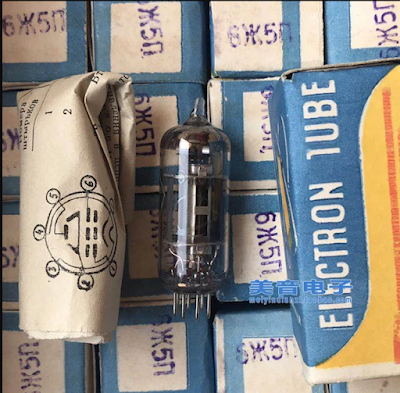
A Soviet Tube in Cuba: The "Little Spider"


I hope readers have picked up on the discussion of the Islander DSB rig out of Cuba. We had a bit of a breakthrough on this recently. I've been writing about it on the blog: 

https://soldersmoke.blogspot.com/2024/04/re-building-islander-dsbcw-rig-in-cuba.html 

One thing I think is especially interesting:  The Cubans were using parts taken out of old Soviet TV sets.  One of the tubes used in the VFO section of the Islander was known among the Cuban hams as "the little spider." 

Arnie Coro CO2KK explains why: 

"VFO is made with ONE of the 6 "little spider" 5 pentodes... By the way, I am sure you will like to know why the tube is locally known like that... the ZHE letter of the Cyrillic alphabet is something difficult to pronounce to a Cuban - or any other non slavic for the matter - and it resembles like a little spider on the tube's carton and... that's why it is not a 6 "ZHE" 5 but a 6 "little spider" five!!!"

Friday, April 26, 2024

Re-building the Islander DSB/CW Tube Rig in Cuba

The VFO Board

The "motherboard" for an Islander
Islander boards recently obtained in Cuba by CO7WT

Pavel CO7WT is making great progress in re-building an Islander DSB rig, the same kind of rig that got him started in ham radio, and that was so popular in Cuba years ago.  Here are some background blog posts on this rig:  https://soldersmoke.blogspot.com/search?q=Islander  In essence, the Islander was the earlier tube DSB/CW rig; the Jaguey was a later, solid-state DSB/CW rig. 

When they get this Islander going, hams outside Cuba should definitely try to work this re-creation of an important rig. 

Thanks Pavel for all the information.  I will share with the group info that Pavel sent about temperature stabilization techniques used on this rig.  

Pavel CO7WT writes: 

Great news, today I received the package from my colleague in zone 6.

Two original islander motherboards and one from the vfo!

I'm doing a search among old technical friends in the city and in the country to see if I can put together at least a transceiver motherboard.

Audio triode-pentode is easy, as is tx pentode and audio double triode.

The difficult ones would be the 6cb6 and 6bz6 of the receiver... At least according to what I have polled among my local friends...

Tomorrow some friends are going to start looking for bases and valves that can be used to build a trx islander.

All out of pure nostalgia. I intend to make it qrp, that is, up to the output pentode, which there is between 3-5W of power, that is enough for me.

I am looking for alternatives for small sources, perhaps I will use switching for the filaments and we will see what I can get for the 180-250v of the plates.


Earlier: 

CO7WT here, built a pair of the Islander back in the time, the most scary part was the power supply.

The 600V is 300ish V from the transformed DOUBLED stright from the transformer and if you look closely on the diagram the doubling capacitor need to be of good quality otherwise it will explode in the spot.

As you can imagine, using scrapped parts means that very often this capacitor explodes, even after a few months of duty, that was a common problem.

We used to use 47uF/800v from Germany that was almost easy to obtain, but exploded like fireworks a given day.

Later I learned that if you put a resistor of about 1k 5W in series and work it for a while like this [no real voltage at the end] it will behave in the future and this trick saved many, a trick that was shared with Coro CO2KK and he found the explanation on the taming/training of the dielectric after storage/inactivity will prevent it from exploding.

I think he made mention this on a DXers Unlimited program...


Monday, April 8, 2024

The Doug DeMaw Article that got me into Homebrew Double-Sideband

Just click on the images for a better view


Pete WB9FLW asked for this.  This was an important article for me -- it paved the way for my entry into homebrew phone gear -- this article was the basis for my first DSB transmitter, built in the Azores. 

I think Doug was a bit optimistic in saying that SSB operation was possible with this rig.  Maybe it was possible for Doug, but for most of us DSB is just a LOT easier to get going than SSB.  (I know that some people don't believe this, but I note that most of these folks have built neither DSB nor SSB rigs.  It always seems easier before you start to melt solder.)  

Be sure to check out the 10 meter DSB rig recently built by Mike WU2D.  He has 6 or 7 good videos on this project, including this one: https://www.youtube.com/watch?v=xThoAMv4zrw

Tuesday, March 5, 2024

A Contact with my Old Azorean DSB Transceiver


I've been thinking about balanced modulators, and I wanted to see how some of my early circuits performed.  So I pulled this OLD Double Sideband rig off the shelf and fired it up. The balanced modulator -- and everything else! - worked fine,  and I soon made contact on 17 meter SSB with Gene, AB9GK. 

This was the first DSB transceiver that I ever built.  I made this out in the Azores, probably in 2000 or 2001.  Years later I had replaced the RF power amplifier with a "JBOT" (Just a Bunch of Transistors) designed by Farhan.  

Over on my YouTube channel a comment came in from my friend Jack:  

"Looking inside and seeing the o-scope probe in place while the radio was on the air reminded me of neurosurgery where the patient is awake and talking while the surgeon probes different brain regions soliciting feedback. Sure, ham radio isn't neurosurgery, but it's not too far at times. Also, you already have rocket science covered."


Here is an article about my build of that first rig:


I think the article captures well the trials and tribulations faced by new homebrewers, perhaps with the twist that comes from being out in the middle of the Atlantic ocean.  

Mike WU2D is having similar fun with his homebrew 10 meter DSB transceiver: 

I was struck by how similar Mike's early QSO experiences were with mine.  We both put our DSB transmitters on the air before they made their way into real cabinets or boxes. 

Here's mine from 2001 in the Azores: 


Thursday, February 22, 2024

Some of my Double Sideband Rigs: Azores, Virginia, Dominican Republic


The above video describe a round of mods to the much modded DSB rig. And my alleged winning of the ARRL Sweepstakes (in a very elite category). 

The video above shows where I took the rig in 2014.  Bahia Rincon, Samana peninsula, Dominican Republic.  You can also see my power supply. 

Here is an article on the first DSB rig that I built, out in the Azores:  

https://www.gadgeteer.us/17METER.HTM


I think the article captures well the trials and tribulations faced by new homebrewers, perhaps with the twist that comes from being out in the middle of the Atlantic ocean.  

Mike WU2D is having similar fun with his homebrew 10 meter DSB transceiver: 

I was struck by how similar Mike's early QSO experiences were with mine.  We both put our DSB transmitters on the air before they made their way into real cabinets or boxes. 

Here's mine from 2001 in the Azores: 

Sunday, July 16, 2023

The Super Islander Mark IV -- A Cuban DSB Transceiver Made From CFL Lightbulb Parts


Trevor Woods also sent us this report from Arnie Coro.  It is not clear to me what difference (if any) there is between the Super Islander Mark IV and the Jaguey Five (described yesterday).  But the bit about using parts from old CFL bulbs is interesting.  This was something championed by Michael Rainey AA1TJ several years ago.  See: https://soldersmoke.blogspot.com/2009/01/soldersmoke-98.html  
and:
https://www.qsotoday.com/transcripts/aa1tj

April 2010:

Today, I will be answering a question sent by listener Bruno from Croatia... Bruno picks up our English language programs via Internet, but he is now also listening on short wave too. He sent a nice e-mail message asking me about the latest version of the Super Islander amateur radio transceiver, because he wants to build one.

Well amigo Bruno, the Super Islander Mark IV is now on the air, and results are very encouraging considering that it is a 40 meters band transceiver built using recycled electronic components.

The Mark IV uses a totally different approach to the receiver design, and it adds two solid state audio filters.

Amazing as this may sound, some of the electronic components used to make the Super Islander Mark IV transceiver came from the circuit boards of broken or damaged Compact Fluorescent Light Bulbs... and that means that there is virtually an endless supply of those parts.

Here is now amigo Bruno, and amigos listening to the program at this moment, a brief description of the Super Islander's Mark IV receiver module.

It starts with a simple resistive signal attenuator that feeds a dual tuned bandpass input filter.

The filter has a limited bandwidth , chosen so as to limit response to out of band signals... The filter is followed by a cascode transistor radio frequency amplifier stage, that feeds a broadband four diodes product detector.

Low level audio from the product detector goes to the audio filtering and amplifying module, made with discrete transistors, of which several of them are also recycled from the Compact Fluorescent Light Bulbs circuit boards...

This version of the Super Islander, the Mark IV , is radically different from any previous ones, as we have now switched over to a totally low cost solid state design , that can be easily reproduced because it uses very common electronic components and straightforward , easy to adjust circuits.

In our upcoming mid week edition I will describe the VFO, or variable frequency oscillator and the transmitter module of this unique low cost amateur radio transceiver, the Super Islander Mark IV... about the lowest possible cost transceiver that will make possible regular two way ham radio contacts on the 40 meters band using either voice or radiotelegraphy modes.

Saturday, July 15, 2023

The Jaguey Five -- The Solid State Cuban DSB Rig -- Circuit Description

Obviously we need a picture of a Jaguey transceiver. 
"Made in Jaguey Grande" 

Trevor Woods found this report from Arnie Coro (SK) CO2KK: 

February 2009: 

Here is now item three in detail: It was quite a long time ago, when I heard about a nice project sponsored by IARU, the International Amateur Radio Union, that was promoting the design of a kit, a simple single band transceiver kit that could be sent in a small air mail parcel to radio clubs in Third World nations which could then deliver them to would-be radio amateurs, and help them build and align the radios... But, unfortunately I lost track of the project, and as many of our listeners may realize there is still a great need of such a project... Past efforts along this line have had some problems, among them the mistaken approach of using of very sophisticated electronic components that in case of a breakdown would be impossible to replace locally; and also, all attempts seemed to try to make the transceiver an ultra- or near-ultra-miniature radio, something that won't help at all with beginners...

So, when I recenlty received an e-mail from Canada, asking what I thought about reviving this great idea, our Canadian amigo asked what we had already done here in Cuba, with our JAGUEY double side band plus CW 10 watt transceiver that went up to REVISION NUMBER 5. , This was the last upgrade, done about three or four years ago, and we named it the Jaguey FIVE, as it generates 5 watts of CW... The Jaguey FIVE was a low parts count, not miniature, easy to build single band transceiver that used readily available components, instead of sophisticated state of the art parts...

In order to please the friend who wrote about this topic, here is a brief, on the air, description of our Jaguey FIVE and by the way, Jaguey is the name of a town, actually it is Jaguey Grande, or big Jaguey, and the Jaguey is a beautiful tropical tree... The original Jaguey transceiver originated in that Matanzas province town in 1982,

The receiver part starts with a simple yet effective RF attenuator, then it feeds a bandpass
filter made of two tuned circuits... we use shielded IF transformers from old TV sets 4.5 megaHertz audio chains... A simple bipolar NPN small signal transistor grounded base amplifier feeds a homebrew double balanced mixer... and we "discovered" quote, unquote, that the antenna balun transformers used in TV sets, the 300 to 75 ohms baluns, had a ferrite core with two holes that makes a wonderful broadband transformer for the double balanced mixer...

We use computer diodes removed from defunct ISA old computer cards and motherboards and developed a very simple test jig to match the diodes... The double balanced mixer is fed on the other port from a simple three transistor oscillator, of which we have two versions, one using three NPN bipolar transistors and the other one using an FET oscillator followed by two bipolars... at the output of the mixer we have AUDIO, as this is a direct conversion receiver, amigos!!!

Now we amplify the audio using discrete components and again we have two versions of audio filters, one with bipolar NPN transistors and the other using a very common operational amplifier IC... The audio power output stage also is available to the builder in two versions, one using discrete components and the other using an integrated circuit audio amplifier that is locally available here in Cuba and produces a booming 2 watts of audio, with a lot of gain and rather low noise! This is the audio IC used by the most popular TV set in use here in Cuba, so we were able to obtain them from the TV repair shops at low cost.

Well, that's why I will describe as a flexible design... again, no attempt is made to make the Jaguey single band amateur transceiver a miniature rig, as miniaturization is definitely not for beginners!!! And following up this description of the receive section of the Jaguey, in our upcoming mid-week edition of Dxers Unlimited, I will describe the transmitter section of the rig,that shares the same variable frequency oscillator with the receiver.... I think that a new more up to date version of the Jaguey transceiver could very well be made available in kit form, with large-sized and easy to assemble circuit boards. The old Version 5 uses three circuit boards, one for the receiver, one for the VFO and one for the transmitter, so the newcomer can assemble just the receiver and start listening to amateur radio communications before having his or her own ham license!!!

You are listening to the weekend edition of Dxers Unlimited coming to you from Havana on the air and on the web at our Dxers Unlimited blog.

----------------------

A video of Jaguey Grande, Cuba: https://www.youtube.com/watch?v=krblz_5o6jU

Earlier posts about the Jaguey on the SolderSmoke blog: https://soldersmoke.blogspot.com/search?q=Jaguey

Tuesday, April 11, 2023

Arnie Coro: Jaguey Rig Designed in 1982, More info on the Rig

Jaguey, Matanzas, Cuba

Dxers Unlimited's mid week edition for 23-24 October 2007

By Arnie Coro
Radio Amateur CO2KK
...

My own personal experience with the original JAGUEY direct conversion 
transceiver, designed way back in 1982, is that when used with a well 
designed front end input circuit, those receivers provide amazing 
sensitivity, with signals as low as 1 microvolt easily detected but, 
they do have one drawback, their selectivity or ability to separated 
between stations is very poor. The direct conversion radio receivers are 
used for picking up CW Morse Code Signals , Digital Modes and Single 
Side Band, but they are not good for receiving AM signals, and can't 
pick up FM modulated signals at all...

The original JAGUEY 82 Cuban designed single band amateur transceiver, was tested against a sophisticated and really expensive factory built 
transceiver. The tests showed that our design was at least as sensitive 
as the very expensive professional equipment, registering a measured 
sensitivity of less than one microvolt per meter, producing perfect CW 
Morse Code copy of such a signal. Adding well engineered audio filtering 
to a direct conversion receiver can turn it into a really wonderful 
radio by all standards amigos. 

Radio is a fun hobby, and believe me amigos, there is nothing more 
magical than listening to a radio receiver you have just finished 
building !!!

-----

Peter Parker VK3YE Found a nice description of the Jaguey by Cuban radio Amateur Jose Angel Amador from the BITX40 Facebook Group: 

A translation.  This was apparently in response to someone who thought they'd found a Jaguey schematic: 

"That's not an original Jaguey, that was a simple, single band, unswitched, 5 watt, DSB, kit for beginners with no gear and needing something to put on the license.
Carbon microphone direct to balanced modulator, two stages with 20 dB gain, W1FB/W1CER style feedback, and final with 2 x 2N2102 class B.
The receiver was more like that of the schematic, with a TAA263, easy to get from the FRC in 1978, and headphones. No need for an RF stage: the mixer was overloaded at night with European broadcasts above 7150.
The VFO is also inspired by Solid State Design for the Amateur Radio, a Colpitts with 2SC372 and a low gain feedback buffer with two 2SC372s.
Binocular ferrites were taken from Soviet TV baluns. The conditions of Cuba 1978.
Today I would make an SSB rig with polyphase networks, mixer with 4066,  and VFO Si5351.
The big complication of BitX is the crystal filter, they either get it made, or stick to a recipe, but few have what is needed to measure and tinker with crystal filters.

Sunday, April 9, 2023

Arnie Coro CO2KK (SK) Provides More Info on the Islander DSB rig

Peter Parker VK3YE found this message from Arnie CO2KK in the Wayback Machine.  We continue to look for more information on the Jaguey solid state DSB rig. 

Arnie wrote: 

Several years ago an amateur in central Cuba was approached by some of his young friends to help them build their first rig. CO7PR, Pedro, a telecommunications technician for the phone company, had a vast experience both with vacuum tubes and solid state circuits, plus that special gift of designing and building with whatever is available. After a few days, Pedro came out with the "Islander" prototype, a low parts count, easy to build single band transceiver!

Here is the circuit description of that little radio that has provided many cuban young and old, newcomers to our hobby, with their first rig... and the challenge to improve it.


RECEIVER:

It is a direct conversion, YES, a DC receiver made with vacuum tubes. The very thought of having those tube filaments fed from the AC power supply and at the same time having 80 or 90 dB of amplification made me shudder when I first talked to Pedro on the very popular here 40 meter band! You are LOCO Pedro, I told my good friend... CRAZY, those poor kids are going to hear 50 percent 120 hZ hum when they tune across the 7 megahertz band.

Yes Arnie, you are right, it has a little background hum, but by using a small loudspeaker and small coupling capacitors... it's tolerable! The receiver shares, in its original version, the same antenna input as the transmitter output stage, a PI network, but we soon learned to add a separate LC tuned circuit first and latter a bandpass double tuned input filter...PLUS a signal attenuator... a very primitive but effective attenuator... just a 10 k potentiometer!

For an RF amplifier stage the Islander uses a russian pentode, which is the equivalent of the popular TV IF amplifiers of the 50's... looks like a 6CB6, for those of you that fixed TV sets 40 years ago or so.

The 6 "little spider" five, as everyone knows that tube here,has a lot of gain, and it can be kept rather stable by a judicious choice of screen and cathode resistor values.. Noisy pentagrid converter follows!

The 6A2P... a russian 6BE6, was the first tube type used in the Islanders, later some people tried the ECH81 triode-hexode and found it works better.

The circuit of the 6A2P-6BE6 is quite straighforward... a... you guessed right... PRODUCT DETECTOR... fed from the vacuum tube VFO... and providing its audio output to the two stage audio amplifier.

Audio amplifier is made with a triode-pentode tube of which plenty are locally available from defunct TV's... the ECL82 and the 6F4P and 6F5P of east european and russian manufacture respectively provide a lot of gain.

So... that's your receiver.. quite straightforward, works on 160, 80 and 40 meters by just changing the input filter and the VFO injection, it does NOT provide very good selectivity at all, but during the daytime, when the 40 meter band is used for local and regional contacts, it puts those new hams ON THE AIR!


VFO... the big problem amigos!

CO7PR worked very hard to try to make a stable vacuum tube VFO... and he almost made it..

YES, ISLANDERS drift, some not too much, others are not so good, depending on who built the rig, and how close they followed Pedro's advice at first, and Arnie's CO2KK later (as yours truly became quite involved in the project, as soon as I found that it was THE way of getting all those guys ON THE AIR!)

VFO is made with ONE of the 6 "little spider" 5 pentodes... By the way, I am sure you will like to know why the tube is locally known like that... the ZHE letter of the Cyrillic alphabet is something difficult to pronounce to a cuban - or any other non slavic for the matter - and it resembles like a little spider on the tube's carton and... that's why it is not a 6 "ZHE" 5 but a 6 "little spider" five!!!

The VFO cleverly works at one half the operating frequency... and then it DOUBLES frequency at the plate circuit... output is via a link to the pentagrid or hexode mixer depending on which type you use.

BUT... the VFO also has a second output to the transmitting chain.. Well that's the receiver... OH YES... the VFO is fed from a VR tube, a gaseous discharge voltage regulator similar to a VR-150 or VR-105... CO7PR advises to use the VR105, but when building the Islander, special in the countryside, that's a very hard part to find, as old TV sets don't use VR tubes! So people use whichever VR they can find. ZENERS? They are only available locally for 6 to 24 volts, so they can't be used with this rig.


ISLANDER DSB AND CW transmitter circuit:

From the VFO plate circuit, you pick up 7 mHz energy (usually you must wait at least half an hour for that said 7 mHz energy to be stable enough in frequency) and feed two diodes (ex-video detectors from russian TV type D20) acting as what I like to call BALANCED AND UNBALANCED modulator!

When used for DSB, it is certainly a DSB generator... but when you want to work CW, it must be UNBALANCED.something easy to achieve with just a resistor from the +12 volts line and a switch!

The balanced modulator receives its audio from a carbon microphone capsule salvaged from an old telephone, and conveniently connected to same +12 volts with some additional filtering via biggest possible electrolytic + small ceramic dogbone from TV set IF amplifier as RF bypass... no dogbone capacitor there... strange howls on Islander audio as RF leaks into balanced modulator you know.

So dogbone ceramic capacitor is a must! No, disk ceramics are not locally available, so people must use the next best choice... dogbone ceramics in the 100 pf to 5000 pf range, usually rated at 300 volts or so... (that 300 volt rating we learned the hard way, but more about that later.)

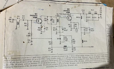
The original version of CO7PR's Islander ran with the carbon microphone, no MIC LEVEL control option, as he really wanted to keep things simple... later versions have audio preamps of various designs, and some even have a sort of primitive compressor.. From the balanced modulator the DSB (plus a little carrier leak that is always there) drives the rig's one or two transistor low level RF amplifier, which is made using whatever NPN silicon transistor is available, usually KT315's salvaged from TV's too. the KT315 is sort of a russian version of the 2N2222, so you understand why we use it here!

RF voltage reaches then the grid of an ex-video output amplifier vacuum tube, and there you are... about 2 to 5 watts of either DSB or CW on 40 meters and a new cuban amateur ON THE AIR!

Before I forget... keying... a little chirpy always because of so many interactions between simple circuits, sometimes not too well shielded, first time builder etc.

BUT... ISLANDER is ON THE AIR providing that young kid from the local junior high school or that doctor that always wanted to be a ham, or maybe the fresh out of school electronic technician, with the fascination of their first ever rig. YES, they drift, and some drift badly, when the frequency determining capacitors in the VFO are not too good... (most of the time), as I said they are a little chirpy. and the receiver's selectivity makes working 40 meters at night almost impossible (although some wizards do make nightime contacts at the low end of 7 mHz) BUT. YES, they are ON THE AIR.

Today there are a few Islanders still on the air, and some are even still built brand new (with many of CO7PR's and CO2KK's mods), but the trend is for all solid state rigs centered around CO5GV's and CO2JA's prototype the "JAGUEY," a design that draws a lot from Wes Hayward's Solid State Design for the Radio Amateur, and as of late, with lots of ideas coming from SPRAT, the G-QRP club magazine and QRPp from NORCAL, the Norther California QRP club!!!

In a future posting I will describe the "Jaguey," too.

-------------

More info on the Cuban DSB and AM rigs can be found here:

https://soldersmoke.blogspot.com/2023/04/more-info-on-cuban-jaguey-solid-state.html 

https://soldersmoke.blogspot.com/2023/03/homebrew-am-from-cuba.html

https://soldersmoke.blogspot.com/2023/03/more-cuban-homebrew-from-80s-and-90s.html

https://soldersmoke.blogspot.com/2023/03/schematics-for-cuban-islander-double.html

https://soldersmoke.blogspot.com/2023/03/the-islander-homebrew-dsb-rig-from-cuba.html

https://soldersmoke.blogspot.com/2023/03/needed-more-info-on-cuban-islander-or.html


Designer: Douglas Bowman | Dimodifikasi oleh Abdul Munir Original Posting Rounders 3 Column