Podcasting since 2005! Listen to Latest SolderSmoke

Sunday, September 29, 2013

Tek Troubleshooting Triumph

Thanks to the manual provided by Jim and the HV test gear provided by Alan Wolke, I was able to finish the troubleshoot on the broken Tek 465.   It is the HV multiplier, U1432.   The cathode voltage is supposed to be -2450.   It initially tested at -1000.    The manual calls for a jumper to be removed to take the HV Multiplier out of the circuit.  As soon as I did that, the cathode voltage went to -2500.   Bingo.
 
Now I have to get a replacement for U1432.    Any carcasses laying around?
 
Thanks guys. 
 
Our book: "SolderSmoke -- Global Adventures in Wireless Electronics" http://soldersmoke.com/book.htm Our coffee mugs, T-Shirts, bumper stickers: http://www.cafepress.com/SolderSmoke Our Book Store: http://astore.amazon.com/contracross-20

BITX Build Update #11 -- Peakin' and Tweakin'

Oh how I love the sound of a newly built receiver!  I'm sitting here listening to G0MJS on 17 meters.  Lots of other stations from across the pond coming in very nicely. 

Earlier in the week I had some sensitivity problems.  I could hear the noise floor, but just barely.  And the receiver just seemed to have trouble inhaling.  So I started poking around.  It seemed that each poke improved things a bit.  I had used Farhan's original schematic (mostly).   Later versions put an additional transistor in the IF amp.  So I went ahead and added that mod.  That helped a bit.  Then I noticed that BFO energy was getting into the AF amp.   So I put a .1uF cap to ground at the input to the AF preamp.  That took care of the RF and did no damage to the AF.  

But the rig still seemed a bit hard of hearing.  This morning Farhan advised me to take a look at the mixers.  I used some junk-box diodes that I didn't know too much about...  I measured the forward resistance and found it to be quite a bit higher than the usual 1N914s.  So I switched all 6 mixer diodes.  That helped noticeably.

I also checked the input bandpass filter.   It seems OK.   In the process I learned to use the EMRFD filter programs (thanks Wes) and the ELSIE filter program (also very nice).

Anyway, the rig sounds great now.   On to the transmitter.  

Farhan advises building the power amplifier on a separate copper clad board.  But I have room for it on my main board.  Should I live dangerously?   


Our book: "SolderSmoke -- Global Adventures in Wireless Electronics" http://soldersmoke.com/book.htm Our coffee mugs, T-Shirts, bumper stickers: http://www.cafepress.com/SolderSmoke Our Book Store: http://astore.amazon.com/contracross-20
Saturday, September 28, 2013

Occam's Microcontroller


Paul, M0XPD, has what I'm sure is a wonderful article on a simple microcontroller-based rig in the current issue of our beloved SPRAT.   I look forward to seeing it.  And I really like the logo with William of Occam (of razor fame). I have encouraged Paul to take a break from the microcontrollers and build something discrete and analog... like a BITX!  

Our book: "SolderSmoke -- Global Adventures in Wireless Electronics" http://soldersmoke.com/book.htm Our coffee mugs, T-Shirts, bumper stickers: http://www.cafepress.com/SolderSmoke Our Book Store: http://astore.amazon.com/contracross-20

Thursday, September 26, 2013

BITX Build Update #10 -- Darling(ton)

Having concluded that I was significantly short on overall receiver gain, I went in yesterday and changed my AF amp from a 40db direct-coupled circuit to a 100db Darlington pair.  I immediately noticed a big increase in audio output. 

I did a quick receiver alignment using my Arduino/AD9860 sig generator.  First I determined the actual bandpass of the crystal filter: 4.998170 MHz -- 5.000960 MHz.   Using a freq counter, I set the BFO at 5.00126.   I immediately started hearing 17 meter SSB signals from the West Coast.  That's always a nice moment:  first signals through a new receiver.  Kind of like "first light" in a new telescope.  Even with the filter ripple, it sounds great.

I think I'm still significantly short of gain.  Audio is still faint. I notice that in the BITX17A they have added a second transistor (Q17) in the second RX receive amp.  Maybe I should try something similar.   Or should I add some gain in the audio chain?

I'm really enjoying this BITX project. 


Our book: "SolderSmoke -- Global Adventures in Wireless Electronics" http://soldersmoke.com/book.htm Our coffee mugs, T-Shirts, bumper stickers: http://www.cafepress.com/SolderSmoke Our Book Store: http://astore.amazon.com/contracross-20

Wednesday, September 25, 2013

Hackers' Paradise

http://hackaday.com/2013/09/23/guest-rant-ham-radio-hackers-paradise/

Our book: "SolderSmoke -- Global Adventures in Wireless Electronics" http://soldersmoke.com/book.htm Our coffee mugs, T-Shirts, bumper stickers: http://www.cafepress.com/SolderSmoke Our Book Store: http://astore.amazon.com/contracross-20

Monday, September 23, 2013

BITX Build Update #9 -- Discretion


With the exception of the PA, all of the stages of my BITX 17 are built.  Over the weekend I put in the DC wiring for the receiver and the inter-stage connections (using the Belden coax with the exposed shield and Teflon di-electric).  It looks nice. 

In my experience, almost all new superhet receivers require a certain amount of debugging and coaxing before they will work.  This one is no exception.  The VFO and the BFO work fine, and all three RF and IF amp stages are also good.  The bandpass filter  that I built passes the desired band and tunes up nicely on the right frequency.  The product detector was acting weird and wasn't balancing out properly, but I got that all sorted.  

I can put an 18.110 MHz signal at the antenna connection and see the signal go through the bandpass filter (with loss), on to the RF amp stage, to the first mixer where it meets the 23 MHz energy from the VFO.  A very messy mixture goes from the mixer to the first IF amp which sends it to the 5 MHz Cohn filter.  The filter works, but it has a lot of ripple, so I need to work on the termination impedances.  Second IF works fine, then the signal goes to the product detector.  AF comes out.  

Here's where the discretion comes in.  Instead of the LM386 chip, I built a 40db two transistor direct coupled AF amplifier. 

So it all works, but the receiver is quite deaf.  I think I just don't have enough gain in the whole system.  I looked at the schematic for the BITX-17 kit.  It very helpfully has total (net) gain figures for the RX.  I can see that my current configuration comes up short.   

Here is what I'm thinking of doing:  I might replace the 40db direct-coupled AF amp with a 100 db Darlington pair.   I really like the discrete Darlington AF amp that KD1JV has in his "all discrete" transceiver:
http://kd1jv.qrpradio.com/ADC/ADC-40.htm  Nice.  3 2N3904's driving a speaker.  I may use that.  
 
Our book: "SolderSmoke -- Global Adventures in Wireless Electronics" http://soldersmoke.com/book.htm Our coffee mugs, T-Shirts, bumper stickers: http://www.cafepress.com/SolderSmoke Our Book Store: http://astore.amazon.com/contracross-20

Wednesday, September 18, 2013

BITX Build Update #8


Big progress on the BITX:  All the bidirectional amp stages are done.   A bag of 20 5 MHz crystals arrived from Mouser today.  I put one in the BFO/Carrier oscillator and it fired right up.  I'll soon be checking frequencies on these crystals, looking for four that are closest in frequency for use in the filter. 

While waiting for the mail I built the audio amplifier for the receiver (lower left corner in the picture above).   Here I need some advice/encouragement:  In an effort to keep this rig "all discrete" I decided to dispense with the LM386, and replace it with an AF amp using individual transistors.  I found a circuit in the 1980 ARRL Handbook that I liked.   It has two direct coupled transistors, one NPN, the other PNP.  I went with a 2N3904 and a 2N3906.   The Handbook said it would yield 40 db gain.  I figured this was a close enough replacement for the 46 db gain of the LM386.  

As usual, I'm not sure of the impedance matching.  I built the first AF stage from the BITX schematic (the stage that precedes the LM386).  It goes to a 10K pot.  The wiper of the pot would normally go into pin 3 of the LM386.   I have the wiper going through a 4.7 uF electrolytic into base of the first transistor.  The Handbook says the circuit has an input impedance of 1000 ohms.  Does my arrangement sound OK? 

Output impedance from this Handbook circuit is also 1000 ohms.  I tried it with some HI-Z headphones that I have, putting AF in from my Maplin AF sig generator.   It sounds OK.   Not a LOT of audio available.  But OK.  I may need one more stage to drive a speaker.     

Our book: "SolderSmoke -- Global Adventures in Wireless Electronics" http://soldersmoke.com/book.htm Our coffee mugs, T-Shirts, bumper stickers: http://www.cafepress.com/SolderSmoke Our Book Store: http://astore.amazon.com/contracross-20

Tuesday, September 17, 2013

Inside a Tek 465


The TEK 465 'scope is as they'd say back in the Bronx "a piece of work."  It has real character.  Perhaps a bit too much.  If you look closely, you'll see transistors in sockets.   I had kind of gotten my head around that, when I noticed that many of the transistors were not in sockets.  They looked like they had been soldered to into the holes in the PC boards.  But NOOOOO!  They are snugly in the holes, but they are NOT soldered in!  You can pull them out, then (if you are lucky!) slide them back in.  There is even quite a bit of "ugly construction." with connections floating in the air.  You can really see the influence of tube era thinking in this instrument.

I think I have narrowed the problem down to the HV supply.  Alan Wolke is lending me a high voltage probe.  I hope to be able to get it fixed this weekend.  I need to get it working because my BITX 17 is nearing completion and I'll need the 'scope for the lineup and de-bugging.

The picture above is from:  http://www.eevblog.com/forum/projects/tektronix-465-repair-and-restoration/   More pictures of the scope are available there.  Also see http://www.spurtikus.de/basteln/repair/tek465/index.html for more scenic views of this instrument.


Our book: "SolderSmoke -- Global Adventures in Wireless Electronics" http://soldersmoke.com/book.htm Our coffee mugs, T-Shirts, bumper stickers: http://www.cafepress.com/SolderSmoke Our Book Store: http://astore.amazon.com/contracross-20

Sunday, September 15, 2013

Battushig has The Knack (Mongolia and the MOOCs)

"How does a student from a country in which a third of the population is nomadic, living in round white felt tents called gers on the vast steppe, ace an M.I.T. course even though nothing like this is typically taught in Mongolian schools?"

"Most homes in Ulan Bator have Internet connections, and almost everyone, including nomads, has at least one cellphone. Even on the steppe, with only sheep in sight, you can get a signal."

http://www.nytimes.com/2013/09/15/magazine/the-boy-genius-of-ulan-bator.html?pagewanted=all&_r=0

Our book: "SolderSmoke -- Global Adventures in Wireless Electronics" http://soldersmoke.com/book.htm Our coffee mugs, T-Shirts, bumper stickers: http://www.cafepress.com/SolderSmoke Our Book Store: http://astore.amazon.com/contracross-20

BITX Build Update # 7


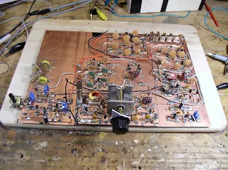
As you can see (above) I've made lots of progress on the BITX-17.  Going counter-clockwise from the lower right, you can see the mic amp, the BFO/carrier oscillator, the first mixer, the first and second bi-directional amplifiers, the diode ring VXO mixer and the VXO.

I plan on building the whole rig (including the power amplifier stages) on this wonderful piece of PC board (thanks to Jim, W8NSA).

I had what I thought was the brilliant idea of using LEDs for  all the T/R switching diodes.  I thought I'd use red for receive and blue for transmit.  I consulted with the BITX yahoo group and cooler heads prevailed.

The design has an LM-386 as the speaker amp.  I'm kind of bothered by this -- I'd prefer an all-discrete component rig, so I am thinking of building an AF amp with discrete transistors instead, perhaps the circuit from Roger Hayward's RX for the Ugly Weekender.  What do you all think about this? 

I'm having a lot of fun building this rig.  If anyone out there is looking for a fall/winter project, build one of these.

I have to order some 5 MHz crystals for the filter and oscillator.  Mouser has them at about 70 cents each.   


Our book: "SolderSmoke -- Global Adventures in Wireless Electronics" http://soldersmoke.com/book.htm Our coffee mugs, T-Shirts, bumper stickers: http://www.cafepress.com/SolderSmoke Our Book Store: http://astore.amazon.com/contracross-20

Saturday, September 7, 2013

BITX Build Update #6: Rock Steady


So, having given up on the VFO,  this week I built a VXO.  The IF in my W4OP-built Barbones Superhet is at 5 MHz.   That receiver has a VXO running at 23.133-23.168 MHz with two crystals switchable from the front panel.  My plan is to build a 5 MHz filter for the BITX 17.  So I just plucked one of the crystals in the Barebones RX and used it to test and tweak the VXO.  Trying different values for the series inductor, I got wide variations in freq swing.  With .7uH I could only pull the rock 9 kHz (too little).  With 5.6 uH, it was pulling 434 KHz (way too much -- it was acting like a VFO). 3.213 uH was just right:  With my 19-148 pF variable cap (with 53pF in series) I got a swing of 22 kHz, with crystal-oscillator stability.

I know, I know:  I could have done this with a DDS chip, or with an SI570.  But simplicity is a virtue, and the BITX is all about simplicity, right?  Having recently built a DDS RF generator, and now this simple three transistor device, I must say that I like the simple analog circuit better.   But hey, that's just me.  I'll talk about this in the next podcast.

Today I built the mic amp circuit.  You can see it off to the right of the VXO.

One of these days I'm going to have to actually troubleshoot and fix my Tek 465.  But I'm
afraid of that thing!  The voltages in there are HIGH, and so is the circuit complexity.  


Our book: "SolderSmoke -- Global Adventures in Wireless Electronics" http://soldersmoke.com/book.htm Our coffee mugs, T-Shirts, bumper stickers: http://www.cafepress.com/SolderSmoke Our Book Store: http://astore.amazon.com/contracross-20

Moon Launch from Virginia (video)


NASA launched a mission to the moon last night.  The rocket went out of Wallops Island, Virginia and was visible from Washington D.C.   I forgot about it, so we missed seeing it ourselves, but this fellow got a nice view from the balcony of his Washington apartment. 


Our book: "SolderSmoke -- Global Adventures in Wireless Electronics" http://soldersmoke.com/book.htm Our coffee mugs, T-Shirts, bumper stickers: http://www.cafepress.com/SolderSmoke Our Book Store: http://astore.amazon.com/contracross-20
Designer: Douglas Bowman | Dimodifikasi oleh Abdul Munir Original Posting Rounders 3 Column