Podcasting since 2005! Listen to Latest SolderSmoke

Monday, August 28, 2023

But How Does the Michigan Mighty Mite REALLY Work?

Dean KK4DAS and I were talking to Mark, a new homebrewer.  After we sang the praises of the Michigan Mighty Mite,  Mark asked us a good question:  How does it really work? 

I guess the starting point for analysis is the Barkhausen criteria (that Pete N6QW taught us):  essentially you need enough feedback to overcome losses in the circuit, and this feedback has to be in phase with the signal at the input.  The MMM is clearly oscillating, so the question becomes, "How does this very simple circuit meet the Barkhausen criteria?" 

Here goes: 

Even though it is a very simple circuit, it is worthwhile to separate out the things that it has to do: 

1) It needs to set the AMOUNT of feedback.    This is done by the tap on L1.  Too low down on the coil, and it is too close to ground through the .05 uF capacitor (not enough feedback).  Too high on the coil and you get too much feedback.  This is like an inductive voltage divider. 

2)  It needs to make sure that this feedback is in phase with the input signal. Positive feedback. Q1 is an inverting amplifier.  So it supplies 180 degrees of phase shift. As the signal at the base goes more positive, the signal at the collector goes more negative, and vice versa.  But we need an additional 180 degree shift to bring the output signal in phase with the input signal.  Here is the key:   The crystal provides the other 180 degrees of phase shift.  See


I tested this:  A 3.579 MHz crystal does provide the needed phase shift:  It introduces a shift of about 190 degrees.  Check out this very cool picture. The two scope probes are looking at the input and the output of the 3.579 MHz crystal with 3.580 MHz frequency coming from my HP sig gen. 

Click on the picture for a better view.

3) It needs to filter out other signals -- the 365 pf variable cap resonates with L1 at around 3.579 MHz.  This results in maximum circulating current through L1 at this frequency. 

4) It needs to match impedance to the antenna.  L2 wound over L1 forms the secondary of a transformer and efficiently moves the energy from the MMM to the antenna.  Think about the gears on your bike. 

The 10k resistor biases the base of the transistor, keeping it on.   The 27  ohm resistors limits the current through the transistor, preventing it from burning up. Note:  the 27 and 10k resistors should NOT be connected directly to each other.  There is no dot in the schematic. This causes some confusion among builders. 

The .05 uF capacitor does two things:   It grounds the L1/365pf tank circuit for RF (but not for DC).   It is less than 1 ohm at 3.579 MHz.   And it helps reduce (smooth out) key clicks (very sudden on-off changes in the oscillation). 

Wednesday, August 23, 2023

Homebrew Transistors


Hang your heads in shame, my friends.  This dude is getting ready to homebrew his own transistors.  None of that store-bought stuff for him.  He is a few steps away from breaking free of the GLOBAL TRANSISTOR CARTEL that has been abusing us so-called "homebrewers" for so many years.   This guy really puts the home in homebrew. 

Plus he has a seriously cool shop enabling him to do some excellent metal and chemical work.  

Thanks to Hackaday for alerting us to this. 

Sunday, August 20, 2023

15 Meter Homebrew SSB Rig As Heard in Mexico City

 19 August 2023. Ralph XE1RK recorded part of our QSO and played it back to me. Thanks Ralph!

I was running about 75 watts to a hex beam aimed Southwest.

Saturday, August 19, 2023

Valveman -- The Story of Gerald Wells


Don't be deterred by the annoying test patterns at the start of this video.  Just skip past them.  The rest of the video is quite good.  Or you could just click on this link and avoid the first 83 seconds of test pattern:  https://youtu.be/Y8w6iwaAGJ4?t=83

Gerald Wells has been mentioned on this blog before, but I don't think we've ever presented the full documentary on this fellow.  Here it is.  Gerry is clearly one of us: a radio fiend, obsessed (as he admitted!) with wireless, a victim of THE KNACK.   

George WB5OYP of the Vienna Wireless Society got to meet Gerald Wells and visit his museum. George alerted me to this video.  Tony G4WIF also was able to visit Gerry and his museum. 

The documentary is full of interesting stuff, and is, in itself, a Knack Story.  Wells mentions the Crippens murder so well described by Eric Larson in "Thunderstruck."  It was this crime that brought radio to the center of public attention.  

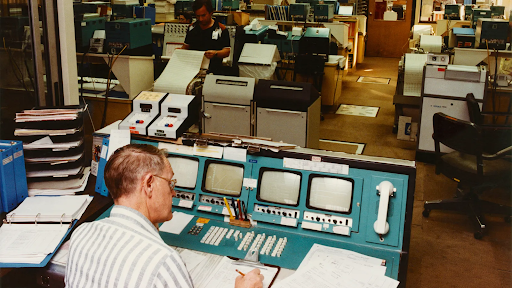
More Ancient Technology Keeping Space Missions Alive


 https://www.bbc.com/future/article/20230815-the-ancient-tech-keeping-space-missions-alive

Three cheers for software.  Really. 


Wednesday, August 16, 2023

Working Indonesia and Chile with new 15-10 Homebrew Transceiver


Conditions were good this morning, and the Radio Gods continue to favor homebrew rigs.  I got on 15 meters SSB with the new 15-10 dual bander and quickly worked YH0AD in Jakarta (about 10,000 miles).  A few minutes later I talked to YB2MVD; he was a bit further east on Java.  I shot a video of the QSO with YB2MVD.  He said I was 59.  

I then switched to 10 meter SSB (same rig) and worked CE4PS in Chile (5,000 miles).   

TRGHS. 

The antenna for all these contacts was my K4KIO Hex Beam.  I was running about 75 watts from the .1kW CCI amplifier. 


Tuesday, August 15, 2023

The Wizard of Kerala (India) -- Denny VU2DGR -- SDR and HDR

 
His signal was just booming in on 20 meter SSB yesterday evening.  It was one of the strongest signals I've heard from India.  I wasn't able to get through the pileup, but I heard mention of a homebrew station at his end...  Sure enough a look at his QRZ.com site shows that a LOT of solder has been melted in his shack.  Both SDR and HDR stuff.  Tube projects including an 807 amplifier made from "components collected from the scrapyard." And a homebrew 20 meter Moxon.  Check it out: 


FB Denny!

Kerala is on the southwest tip of India.  It is something of a hotbed of technological innovation.  My only Indian contact using my current series of homebrew dual-banders was with VU3TPW -- Renju is also in Kerala. 

Monday, August 14, 2023

You have heard of the International Geophysical Year (IGY). But have you heard of the IQSY?


International Quiet Sun Year.  1964-1965.  Yes, that was a thing.  

Tuesday, August 1, 2023

Voyager, Canopus, JPL, and 74xx Logic Chips from the early 1970s


"So somewhere out there in interstellar space beyond the boundary of the Solar System is a card frame full of 74 logic that’s been quietly keeping an eye on a star since the early 1970s, and the engineers from those far-off days at JPL are about to save the bacon of the current generation at NASA with their work. We hope that there are some old guys in Pasadena right now with a spring in their step."

https://hackaday.com/2023/07/31/just-how-is-voyager-2-going-to-sort-out-its-dish-then/


Sunday, July 30, 2023

Understanding Maxwell's Equations (video)


And you should also look at the accompanying web site: 

Writing about the equations, the author notes, "They are formidable to look at - so complicated that most electrical engineers and physicists don't even really know what they mean.  This leads to the reason for this website - an intuitive tutorial of Maxwell's Equations. I will avoid if at all possible the mathematical difficulties that arise, and instead describe what the equations mean. And don't be afraid - the math is so complicated that those who do understand complex vector calculus still cannot apply Maxwell's Equations in anything but the simplest scenarios. For this reason, intuitive knowledge of Maxwell's Equations is far superior than mathematical manipulation-based knowledge. To understand the world, you must understand what equations mean, and not just know mathematical constructs. I believe the accepted methods of teaching electromagnetics and Maxwell's Equations do not produce understanding. And with that, let's say something about these equations.

Thanks to Armand WA1UQO for sending me the wonderful book about Faraday and Maxwell that put me -- once again -- on the path toward a deeper understanding of their work.  

Friday, July 28, 2023

Phase Noise and the Radio Amateur

A weak signal disappears in the phase noise of the stronger signal.

The March 1988 QST provides a relatively clear explanation of what phase noise really is:

Highlights: 

Phase noise is an undesired variation in the phase of the signal. In this case, an oscilloscope shows that the time between zero crossings of the signal varies over time when compared to the zero crossings of an ideal sine wave. An exaggerated example of phase noise is shown above.

Phase noise on an oscillator signal has exactly the same effect as frequency modulating the oscillator with noise.

Whenever a carrier is passed through a mixer, the phase noise of the oscillator driving that mixer is added to the carrier.

Phase noise on a transmitted signal causes effects identical to phase noise generated in a receiver.

Any signal that reaches a mixer in the receiver is modulated by the phase noise in the local oscillator driving that mixer. As such, the signal appears to have at least as much phase noise as the local oscillator. Thus, sufficiently strong signals off the receiving frequency can degrade receiver sensitivity by raising the noise floor at the receiving frequency. Receiver dynamic range is reduced as the noise floor rises.

With a frequency-shift-keyed or- a phase-shift-keyed signal, the close-in phase noise limits the maximum bit error rate that the system can achieve. Both of these effects can be quantified once the communications system is defined. With an SSB voice signal, the effects are much harder to predict, but excessive phase noise does degrade SSB signal intelligibility to some extent.

--------------------------------
Receiver guru Rob Sherwood provides some very useful historical background on his web site:

http://www.sherweng.com/documents/TermsExplainedSherwoodTableofReceiverPerformance-RevF.pdf

Phase Noise: Old radios (Collins, Drake, Hammarlund, National) used a VFO or PTO and crystal oscillators to tune the bands. Any noise in the local oscillator (LO) chain was minimal. When synthesized radios came along in the 70s, the LO had noise on it. It is caused by phase jitter in the circuit, and puts significant noise sidebands on the LO. This can mix with a strong signal outside the passband of the radio and put noise on top of the weak signal you are trying to copy. This is a significant problem in some cases: You have a neighboring ham close by, during Field Day when there are multiple transmitters at the same site, and certainly in a multi-multi contest station. You would like the number to be better that 130 dBc / Hz at 10 kHz. A non-synthesized radio, such as a Drake or Collins, has so little local oscillator noise the measurements were made closer-in between 2 and 5 kHz.   

-------------------------------------
Experimental Methods in RF Design (EMRFD) has this to say about phase noise:

"The local oscillator is a critical part of any communications system. Modern transceiver performance is often compromised by LO systems that suffer from excess phase noise, effectively limiting the receiver dynamic range. While quiet oscillators, those with low phase noise, can be built using traditional methods, these circuits often lack the thermal stability of a synthesizer.... Frequency synthesis is not, however, the answer to all the LO problems presented to the experimenter.  Some PLL synthesizers are burdened by excessive phase noise. Those using DDS, while quieter, emit spurious outputs, often in profusion.  Both use an excess of digital circuitry that can often corrupt a receiver environment."  page 4.1
   
"At first glance, phase noise sounds like an esoteric detail that probably has little impact on practical communications.  This is generally true." page 4.12 

--------------------------------------

Hans Summers G0UPL analyzed and measured the phase noise of the Si5351a chip: 

http://qrp-labs.com/qcxp/phasenoise.html

------------------------------------

DC4KU appears to be using the crystal filter method used by Hans: 

https://dc4ku.darc.de/Transmitter-Sideband-Noise_DC4KU.pdf

------------------------------------

Martien PA3AKE has done a lot of great work on this topic.  See: 

https://martein.home.xs4all.nl/pa3ake/hmode/dds_pmnoise_intro.html

-----------------------------------

Dean KK4DAS commented on the phase noise video of the IMSAI guy: 

Watching the video I was reminded of Segal's law roughly paraphrased as follows.:

A man with one spectrum analyzer knows his phase noise. A man with two is unsure.

Designer: Douglas Bowman | Dimodifikasi oleh Abdul Munir Original Posting Rounders 3 Column