Podcasting since 2005! Listen to Latest SolderSmoke

Sunday, February 28, 2016

75 and 40 Meter AM on my HQ-100 (Videos) + Digital Display


And here is how I sample the oscillator frequency for the digital counter.  I use an old trick:  I wrap some wire around the oscillator or mixer tube.  I made the coil out of an old coil form. I had to play around with the number of turns to get suitable pickup on both 160 and 40 meters.  The San Jian board allows for IF freq offset.  I use a similar arrangement on the transmit side with the DX-100.  By the way, the box that houses the two displays is the carcass of one of the Heath QF-1 Q multipliers from which I heartlessly pulled the nice reduction drive variable caps for use in my BITX rigs.  


Add caption

Saturday, February 27, 2016

Sputnik Replica Transmitter, an "Error" in the Sputnik Schematic, and Why 20.005 MHz?


Mark K6HX pointed me to very interesting Hackaday article on Frank PA3CNO's Sputnik transmitter replica.  As blog readers will recall, we went through a period of Sputnik-mania a few years ago:  http://soldersmoke.blogspot.com/search?q=sputnik  Chief Designer Comrade Mikhail Rainey AA1TJ sent me some of the Russian tubes (like those pictured above). 

The Hackaday article pointed to our post reporting that Oleg RV3GM had found the schematic:
http://soldersmoke.blogspot.com/2013/04/sputnik-schematic-found.html   Stefan reports that PA3CNO found "an error" in the original Soviet schematic:
http://www.radio.cc/post/Franks-power-supply-for-sputnik    A mistake you say?   HAH, I say!  Hah!  This must have been part of a sinister commie plot to prevent the capitalist imperialists from ever being able to reproduce the glorious transmitter of the Soviet people.  They almost succeeded. 

Just kidding.  

In the course of looking through our old Sputnik posts, I came across a question I posted:

I have a question: OK so the crafty Soviets picked 20.005 MHz for some good reasons: Being so close to the WWV freq, it would be easy for hams and SWLs to find it with precision. In the November/December 2007 issue of "Break In" (from NZ -- thanks Jonathan-san!) ZL3DW notes that this frequency selection would allow a receiver set to exactly 20 MHz to "produce an audio tone plus or minus the Doppler shift without ever going through zero beat." But zero beat with what? Most of the receivers out there would not have had BFOs, right? So the Soviets wouldn't have been using ordinary CW, right? Were they using AM, with the beeps produced by an audio oscillator modulating the carrier? 

Was their diabolical plan to use WWV as the BFO for those using ordinary AM SW receivers?   If so, a 5 kHz separation from WWV seems to be too much right?  Especially when the Doppler shift on approach would push the frequency up a bit. Maybe they just chose this freq to make it easy for listeners to find -- just a bit above WWV.  Comrade Rainey surmised that they were keying the PA stage -- the oscillator "backwave" was at times audible on the ground.

What do you think Comrades?
DSW and 73.

Thursday, February 25, 2016

"Hot Iron" New Issue, Great Articles


I was very pleased to find Tim Walford's "Hot Iron" journal in my e-mail this morning.  Lots of great articles in this edition, including one by a fellow we know:  Pete Juliano!  Pete writes about our esteemed dual gate MOSFETS.  All hail the 40673!  There is also a nice article about superhet receivers using a 6 MHz IF and a very convenient analog LC (yea!) oscillator arrangement.  Another discusses how to use Huff and Puff stabilizers to take care of VFO drift. N4HAY describes his initial foray into the world of homebrewing and how EMRFD helped him.

Hot Iron is free.  Tim writes:  

"Hot Iron is published by Tim Walford G3PCJ of Walford Electronics Ltd. for members of the Construction Club. It is a quarterly newsletter, distributed by e mail, and is free to those who have asked for it. Just let me know you would like it by e mailing me at electronics@walfords.net"

Thanks Tim!

Monday, February 22, 2016

SolderSmoke Podcast 185 -- SPECIAL FEBRUARY ANTENNA SHOW


SolderSmoke Podcast #185 is available

22 Feb 2016

http://soldersmoke.com/soldersmoke185.mp3

Travelogue:  550 feet above Washington DC

Bench reports
Pete:  Simpleceiver update.  Adventures in Raspberry Pi SDR.
Bill:  A daring but failed attempt at divide by 2 I&Q.
Audio Mods on the Hammarlund HQ-100.
Dual Digital Readout for the AM station.

SPECIAL FEBRUARY ANTENNA DISCUSSION
Why we build antennas in February.
Why hams should concentrate on antennas.
The importance of noodling.
Pete's beam project.
Pete's Lazy H.
The pernicious influence of automatic antenna tuners.
Bill's Ray Gun Antenna.
Bill's Moxon and his 160 inverted L.

MAILBAG
Tom Gallagher NY2RF (new ARRL Exec VP).
Mike Rainey AA1TJ on the air with a unijunction transistor.
Dale W9DKB sends me 160 meter book.
Alan Wolke W2AEW builds a Mighty Mite.
Daniel HK4DEI builds a DSB rig in Medellin.
Chris KD4PBJ modulates an AD9850.
Charlie ZL2CTM Builds a Teensy Superhet.
Jim W8NSA -- a Tek 465 goes toes up.
Thomas KK6AHT has roof, needs antenna!
Grayson TA2ZGE homebrewing crystal filters in Ankara.
Ian G3ROO and I had QRP QSO in 2001!
Steven G7VFy sent me a box of VALVES.
Frank KM4AXA repairs a rig and thus adds SOUL to the machine.

Design Wisdom from Allison, KB1GMX


Allison KB1GMX has helped me out of numerous battles with recalcitrant amplifiers.  She provided an interesting contribution on the r2pro mailing list thread that I referenced yesterday:  

Interesting thread...

 I see Rick as having provided the basis and tools and it up to the collective 'US" to use them to 
create that next generation radio.  All you have to do is decide the performance and 
then go about looking at the means to do so.  All the blocks are there.

Dynamic range, how much is enough?  When I'm portable or mobile raw sensitivity is 
more useful as the antenna is usually a compromise.  Overload is easy to handle with
switchable attenuator.  The exception to this was a radio designed for contesting in a 
hostile environment (a KW user 800ft away) if you burn power you get overload 
performance.  Its not a battery friendly radio (RX power is over 1A for headphone output).
Look at what you need and not what you want.

TX power is just adding stages.  I've worked MOSFETs, LDMOS, GaN FETS and there 
are some pretty cool devices out there and some not designated for RF are cheap.
If all else fails the IRF510 gets both raves and derision.  At 12V its a tepid device
but at over 20V and at 24V it starts to wake up and really perform. I've run The WA2EBY
design for a few years at 45W level using two of those push pull at 28V and its clean and 
solid and the original pair are now over 6 years old!  I also run 8 of them  (4x4push pull) 
at 32V at 6M for a cool 210W  with good IMD.  I'd add all the good (high gain, low IMD) 
power fets perform better at 28  or 50V.   For those into CW consider class E as I've 
worked with this and using GaN fets have generated 15W with 82% efficiency at 
13.56mhz (includes driver and osc) and using the lowly IRF510 at 12V a full 10W 
with 85% efficiency. Class E can be amplitude modulated.

As to the thermionic FETs, a 6AU6 crystal osc driving a 5763 for 10W  gets a lot of raves
on 40M from a buddy that runs CW.  The same deal plate modulated can sound good 
at 5-6W AM on 75M.  For those that want more a 6C4, 6aq5, 6146 will get you over 
50W on CW and 25W AM.  Change the bias a little and inject IQ SSB into the driver grid
and be running 50-80W PEP.  A 12BY7 or 6CL6 driving a pair of 6146 will get you into 
the 180-200W DC input range for about 100W.   Remember the hybrid radios solid state 
low level and rugged tubes for the heavy lifting.  The Pi network (or Pi-L) will load anything 
from about 28 to 100ohms more if you use enough taps and variable caps.  That and DC-DC
converter for the HV are not terrible at 80% or better (even the 1960s transistor designs 
were better than 75%).

In the end it all starts with the receiver.  For that you can always start with a 1T4 RF and 
a 1R4 converter and a 1T4 as regen driving a 3V4 audio.  Power it with 45V (five 9V battery)
and a C cell and go portable.  It should run for a very long while.  Hollow fets run well at low 
drain currents.  :)

Allison

Sunday, February 21, 2016

Words of Wisdom from Rick Campbell, KK7B

Rick Campbell KK7B recently responded to a question on the r2pro mailing list.  His answer was so good, and so full of design wisdom that I asked Rick for his permission to post his message here.  Here it is:

I have designed and built several new single band HF rigs for my own use since the R2pro, but have not done any complete transceiver designs intended for others to duplicate.  The R2pro was specifically designed as a set of modules so that a designer can combine an assortment of those modules with others and come up with a transceiver optimized for a particular, personal application.  Much of my recent most design work has been for instrumentation at VHF and UHF, so it doesn't really lend itself to the "high performance at HF" realm.  The R2pro design still holds up well in 2016.

Regarding being inspired to design a new high performance transceiver, I find complete transceiver designs uninspiring, hi.  I personally enjoy coming up with a particular application that isn't well served by anything currently available, and working on some unique design for that particular niche.  Occasionally it has been a large enough niche that I've worked with someone like Bill Kelsey to come up with a commercially available kit of parts, but more often I just design and build a few to fill the immediate need in my lab.  Sometimes that "need" is just a whim, and some of my most enjoyable and technically rewarding work has been to satisfy some personal curiosity or other.

Regarding your wish list:

"Best Sounding Audio Possible" is still the same as it has been since my first receiver with diode ring mixers to do the frequency conversion before any gain, followed by a serious audio amplifier string drawn from the audio recording industry.  In most of my recent work, starting with the R2pro, the limitation on dynamic range inside the audio channel is set by the op-amps.  About 80 dB from the noise floor to non-harmonic artifacts is relatively easy, but you have to be careful.  If the noise floor at your receiver volume control is 80 dB below a volt, that's about 100uV, and well below what you can see on an oscilloscope.  These are very old principles.  Though they haven't been common in the communications receiver field, no breakthroughs are needed, just careful design.  The R2pro is better than it needs to be.

"Good Dynamic Range" is an interesting concept.  I like to design receivers that have good enough dynamic range, which is different for every application, on every band.  Unlike during the 1970s, today most of our receivers have enough dynamic range, in the same sense that cars have had enough wheels since designers figured out that 3 was not enough.  Once you have enough, adding more is not an improvement.

Some of my recent receivers have had a crystal filter between the antenna and first active stage.  Those are stellar, but that's not usually needed.  They do illustrate the point that if you find yourself operating in a hostile EM environment with many very strong nearby signals, there are other ways to address the problem besides in the receiver circuitry.  Ever since I achieved "good enough" for all my personal applications a while back, I've focused on other receiver performance measures.  In particular I try to avoid sacrificing something important to make an improvement in a specification that is already good enough.  I have never been on a hilltop with Wes Hayward when anyone missed a contact because of inadequate dynamic range, but I have been when we missed contacts because the batteries died.

"SCAF type filtering."  I've played with switched capacitor audio filters and other commutating signal processing since the mid 1970s.  Each time I've built one into a  receiver I've run into problems with that danged clock.  I tend to listen at and below the noise floor, and one of my pet peeves is when I can hear anything at all other than pure thermal noise when the receiver is terminated with a room temperature 50 ohm resistor.  Since I routinely record signals for post processing in a DSP system, it is disheartening to discover that some harmonic of the SCAF clock beat against the LO at a particular frequency, ten dB below the noise so you didn't hear it when you made the recording, but 10 dB above the noise floor in your FFT waterfall plot.  So I have avoided such things for my last few decades of instrumentation-grade receiver designs.  When I have a digital dial, I include a switch so it can be turned off when I'm recording weak signals.  None of this applies to you--please continue to experiment with SCAF filters, embedded processors and other generators of digital noise that may well be far beneath the threshold of signals and antenna noise for your particular application.

"Audio output power."  In my lab I generally find about a half watt is more than enough for a radio tuned to a ham band.  In other applications I go as high as 40 watts of audio at the threshold of detectable two-tone IM products.  All of that is nicely covered in the audio literature, and there are a number of good designs available on the web.  The R2pro audio amplifier in EMRFD works well driving a compact, efficient speaker in a quiet room.  For more power output, use bigger transistors and raise the supply voltage up to about 24.  Above that, you need to add Darlington drivers, as in the original R1 and R2 circuit, and you can then raise the voltage up to around 40v with NE5532 op-amps and get more than 20 watts of superb clean audio.  That R2pro audio output stage in EMRFD has been borrowed and modified for more than one very high end professional audio application.

"RF Power" For either audio or RF power, I encourage experimenters to use higher voltages than 12.  Within a few years we should have available some nice GaN transistors that will allow us to use supply voltages up around 80, which really makes it easy to generate many watts of power into either 50 ohm or 8 ohm loads.  If you don't want to wait for GaN, there are some huge N channel depletion mode FETs that run the electrons in vacuum and will easily handle many hundreds of volts on the drain.  They need a separate low voltage supply at an amp or so to generate the electron stream, but are capable of astounding performance, particularly in narrow band applications.  If they hadn't been invented 100 years ago, we'd be all excited about the possibilities now.  A 6146 would just idle along at 5-10w out and last forever.

For my most recent contacts on 40m CW, I used an R2pro and ran a very stable premixed JFET Hartley VFO driving a 6C4 and 6AQ5 output stage.

Enjoy the experiments.

Best Regards,

Rick KK7B
__._,_.___

Saturday, February 20, 2016

Dr. Rufus Turner, W3LF. Homebrew Hero and Radio Pioneer


Thanks to Farhan for alerting me to this great Hackaday article about a homebrew hero who was -- sadly -- unknown to most of us.  He lived in Washington D.C.,  right down the road from where I live now.  The Hackaday article leaves no doubt about it -- Rufus Turner was one of us. He had THE KNACK.  He was a true radio pioneer and homebrew hero.  It is really a shame that we've known so little about him.  


Friday, February 19, 2016

Inside the Hammarlund HQ-100


I continue to work on this old beast.  I picked it up in the Dominican Republic around 1994.  One of the IF transformers had gone open.  I fixed that.  Had to replace the AF output transformer too. And the variable cap that tunes the antenna.  Check out the flywheels!  And the rope and pulley thing.  You don't find those kinds of things in any of those fancy modern rigs. 

Earlier I had removed "the exclusive Auto-Response audio output circuit."  See:
http://soldersmoke.blogspot.com/2016/02/snowed-in-audio-mods-on-hammarlund-hq.html

Today I installed a simple feedback network in the AF amplifiers (as prescribed here:  
http://www.amwindow.org/tech/htm/hqaudiomods.htm

It sounds nice now.   The rest of the bands have been ravaged by some sort of solar event, but 160 seems to be benefiting -- signals last night and this morning were quite strong.  I was being heard by WA1HLR way up in Maine.

UPDATE 20 Feb 2016: After installing the feedback network mentioned above, I noticed a big increase in AC hum.   It was not the electrolytics.  I reversed the feedback mod and the hum went away.  But the receiver continues to sound a lot better with the removal of the Auto-Response output circuit.

Wednesday, February 17, 2016

Just Below 160 Meters -- "Travelers' Information Service"

In the course of working on my 160 meter AM station I came across a strong AM signal a bit below Top Band.  Turns out it is part of something called the "Travelers" Information Service."

The signal from this system on 1.670 MHz is very strong here.  A Shortwave (Midwave!) Listener in Austria heard it too.  Check out the confirmation letter from the Virginia Department of Transportation.  Nice of them to do this.
Here is the QSL letter sent to Austria:
https://remotedx.wordpress.com/2014/06/01/very-rare-reception-vdot-highway-advisory-radio-1680-khz/

They are running 10 watts into a 49 foot tall vertical with 40 radials. They have a text-to-speech system that is constantly describing weather conditions.  Quite useful actually.

I found a web site that lists all the stations of this kind in the US:

https://www.fcc.gov/media/radio/travelers-information-stations-search

I can see that the station I am hearing is just 2 miles from my location.


More information on this system:

https://en.wikipedia.org/wiki/Travelers%27_information_station

Tuesday, February 16, 2016

A Phasing Receiver from Montenegro (Video)


Thanks to Peter Parker VK3YE for alerting us to this beautiful receiver from Bore 4O6Z in Montenegro.  This may be our first ever report on a Montenegrin rig.  And it is a thing of beauty. Bore says it is based on a phasing circuit by homebrew legend V. Polyakov, RA3AAA.

Here is 4O6Z up on the tower:

Monday, February 15, 2016

Snowed In! Audio Mods on the Hammarlund HQ-100


It is snowing here today, so I am stuck in the hamshack.  YEA!

I've had the Hammarlund HQ-100 receiver on the bench because I am building an outboard digital frequency readout for it and for the DX-100.  More on this later.  But as long as I had it on the bench I decided to do a mod to the audio output that has LONG been needed.  

Here is a nice web page that describes the problem and the solution.  The problem is the "Auto Response audio output circuit" touted in the add up above.  Essentially I had to remove the touted circuitry.  The AutoResponseectomy only took me about 15 minutes and the results are quite noticeable.  The old receiver sounds a lot nicer.  I'm listening to 40 meter AM now.  FB.

Here is the page:

The HQ-100 does indeed have "three dimensional beauty."

Sunday, February 14, 2016

"QSO Today" Podcast Interview with Michael Rainey AA1TJ

Picture

Eric 4Z1UG has a really great interview with Michael AA1TJ:


I listened to it as I aligned my HQ-100 receiver and worked on a digital frequency readout for the old receiver.   The interview was the perfect accompaniment for such a project.  Inspirational stuff.  Lots of great info on QRPp and homebrewing.  Mike talks about some of his more famous rigs including the voice-powered New England Code Talker (pictured above).  

I loved the story of Michael carting his DX-100 home in a wagon.  And I really sympathized when he described the harsh reaction of the phone operator to his early efforts at voice modulation.

Strongly recommended!   You won't be disappointed.  Great interview.  Thanks to Eric and Mike.


Saturday, February 13, 2016

ZL2CTM's Teensy SDR SSB Superhet -- Very Cool


Hi Bill

I thought I would drop you a quick line to show you something I have been playing around with for the past couple of weeks. It's a SSB superhet using a PJRC Teensy 3.1 microcontroller (YouTube link below), and a great audio library by Paul Stroffregen. Suffice to say I'm really happy with it.

There is a direct conversion front end, albeit using a VFO 15kHz down from the incoming RF. The 15kHz IF is then fed into the Teensy audio line in which can handle up to 22kHz. From there everything is in software. First is a 2.4kHz BPF tuned to the LSB, followed by mixer with a 15kHz BFO. Finally, there is a 2.4kHz LPF. Next step is to add both CW-wide and CW-narrow filters which can be selected during run time.

As you can tell from the video, my antenna is not the best and I have quite a bit of QRM in the shack. I really need to think about a better antenna, but that's another story.


I have been following your R2 endeavors with interest, and as I said to Pete I will attempt to replicate the R2 on a Teensy. I will try and use the divide by 2 arrangement you tried as the logic looks right.

I will also be adding in a transmitter. For that I'll use the microphone input and then take the audio from the line out straight to the RF pre/power amp. 

I must admit that I really enjoy homebrewing hardware/software hybrids as you get the best of both worlds. As i say that, I wonder how much ADCs cost these days to directly digitize RF...  Now that would be interesting.

I'll say again that I really enjoy following the podcast. I have loved electronics since I was a small boy when my parents bought me a battery, switch and light bulb. This age of cheap DDSs, microcontrollers and the like is amazing, and I get so much enjoyment putting them all together to make functioning ham radios. I hope more get into the homebrew field as the entry barrier is dropping fast.  

Keep up the good work.
73s
Charlie
ZL2CTM


Friday, February 12, 2016

A Snow Day Well-Spent: Chris Modulates an AD9850

Feb 10 at 7:40 AM
Hi Bill and Pete,
My work is closed today due to the snow so I wanted to show you what I've been up to.
I built sort of a test fixture a while back for those cheapie EBay AD9850 boards based on AD7C's DDS circuit using an Arduino Uno as a controller.
Last summer someone posted a link to Analog Devices App note AN-423 on QRP-Tech I think.
It was always on my list of things to try.
Armed with a schematic of the eBay DDS gleaned from Doug Pongrance's website, I got to work. It involved cutting a trace or two on the DDS board using an X-Acto knife.
Two outputs of the DDS chip are fed into a wideband transformer as in the app note's second page and I hung a scope probe off the secondary of the transformer.
Basically you are removing the Rset resistor on the DDS board (marked R6 on mine) and using a 2N7000 MOSFET as an electronic version variable resistor and modulating the MOSFET.
This lead to much frustration over the afternoon. No output on the scope!! Did I make an error or connect something up wrong? I was using the 600 ohm output of my HP652A audio generator. I thought about it during lunch and decided to try the 50 ohm output. Bingo!! At the 3V RMS range setting on the generator I now have some kind of signal. Not a nice sine wave shaped AM output but at least something resembling a clipped sine wave. The circuit is really touchy as far as needing a hefty audio signal in. The output of my iPhone at max volume doesn't turn on the DDS chip.
I set the DDS for 1200 kHz and can listen to it on a Radio Shack portable radio. Varying the audio generator varies the received tone on the radio just like I was expecting.
I just need to figure out what's up with the audio levels.
Chris
KD4PBJ

Thursday, February 11, 2016

Gravitational Waves, A GREAT VIDEO, Phasing, and Joe Taylor K1JT


Wow, you really have to spend 20 minutes and watch the video (above).  It is really well done.  I loved it.  I give it FIVE SOLDERING IRONS!

And big news today!  They did it!  Gravitational waves finally detected.  Here is a good New York Times article that includes a recording of the signal, a nice NYT video that has a good explanation (with phasing!) of how lasers are used in the massive detectors, and mention of Joe Taylor, K1JT, whose Nobel Prize winning work contributed to this great discovery.

http://www.nytimes.com/2016/02/12/science/ligo-gravitational-waves-black-holes-einstein.html?partner=rss&emc=rss&_r=0

Life in the Fast Lane: Potato Semiconductor Chips

Even I, with my luddite tendencies and analog preferences, have recently bumped up against the speed limit of 74 series logic chips.  The Si5351 chip in the I and Q VFO for my phasing receiver will run up to 160 MHz.   But the 74 series inverters and flip flops that I have attached to the output don't seem to want to go beyond about 120 MHz.   Our old friend Thomas LA3PNA tells us how to break this speed limit:

http://www.potatosemi.com/  

Be sure to go their "Milestones of 74 Series Logic" Page.

I like their explanation of the brand name: 

Wednesday, February 10, 2016

Single Sideband + Carrier -- The Collins KWS-1


Back on 2 February I was on 160 AM with the DX-100, talking to WA4PGI.  At the end of our QSO we got a call from a station.  I was at first confused -- was this station calling on SSB?  Or was he calling on AM?   Turns out that he was -- in a way -- on BOTH.  K4DBK was -- I think -- running an old Collins KWS-1, the transmit side of the famous Gold Dust Twins.  Aptly named:  It was built in 1955. 1000 watts output.  $2095.00 in 1955.  Gold dust indeed.  

The really interesting thing about this rig was that it put out CW, SSB and SSB plus the carrier.  I think that was what we were hearing from K4DBK.  FB.   

Does anyone have an e-mail address for K4DBK?  I'd like to drop him a line.

Tuesday, February 9, 2016

Back to Divide by 4 -- Big Improvement in Receiver Performance

Thanks for all the comments and advice.  I have come to understand the wisdom of divide by 4 IQ circuits.  

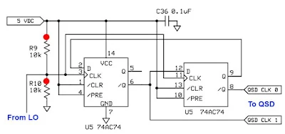
Fortunately it was very easy to convert the divide by two 74AC74 circuit described earlier to a version of the divide by 4 scheme seen above.  (From the SDR Ensemble II Receiver:  http://www.wb5rvz.com/sdr/ensemble_rx_ii_vhf/04_div.htm)

This change provided a great way to observe 1) the improvement in the output signals from the VFO and 2) the resulting improvement in receiver performance, especially opposite sideband rejection.

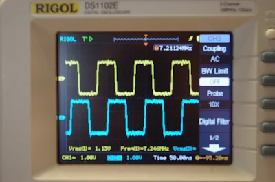
Here are some numbers. I was very pleased to discover that my Rigol scope will measure duty cycle and phase difference. Thanks Rigol!

AD9850 Divide by 4 :  7.212 MHz  Duty cycle: 48.3  Phase Difference:  87-90 degrees

Si5351 Divide by 2:      7.212 MHz  Duty Cycle 49.6  Phase Difference:   83 degrees

Si5351 Divide by 4       7.212 MHz   Duty cycle 49     Phase Difference:  85-90 degrees

Additional improvement came when I switched the power supply to the IQ inverters and Flip Flops.  I switched from 3.3 to 5 volts:

Si5351 Divide by 4       7.105 MHz   Duty Cycle 49.7    Phase Difference:    90 degrees

When I took the VFO box and put it back in the receiver with the divide by 4 scheme and the 5 volt supply I immediately noticed a big difference in performance.  It was obvious that opposite sideband rejection was back to what I had had with the AD9850, perhaps better. 

I have a quick and dirty method of measuring opposite sideband rejection: I put an RF signal into the antenna connector.  I put the 'scope on the audio output.  I tune (on the desired sideband) for 1kHz audio and I measure the output voltage.  Then, with the audio gain and RF sig gen output in the same positions, I tune to the opposite sideband, again tuning for 1 kHz, again measuring audio output.  With the divide by 4 scheme and the 5 volt supply, the opposite sideband was so weak I had trouble measuring it.  I estimate the rejection to be at least 32 db -- this is back in the range of what I had with the AD9850, and significantly better than I had with the divide by 2 scheme. 

Now I just need to figure out how to get the Si5351 VFO sketch to tune above 42.94 MHz.  For some reason it quits at this point, switching down to 2 kHz output, and keeping me on 30 meters and below.

Thanks again to Todd VE7BPO for a lot of help with the hardware and to Tom AK2B for help with the Arduino code.  
   

Sunday, February 7, 2016

Ambition, Greed, and Experiments with a Divide by 2 IQ VFO

Fresh from a great success with the use of the M0XPD divide by 4 I and Q VFO in my Frankenstein Phasing Receiver, I got ambitious.  And greedy.  I wanted more.  More frequency coverage.  More bands.  Divide by 4 can really limit your frequency range.  The AD9850 only goes up to 40 MHz.  Divide by 4 and you can't even get the 30 meter band. 

So I started looking at other options.  Si570 looked nice, but here the lower limit was the problem: 10 MHz.   Even with divide by 4,  that knocks out 160 meters, a band I am very interested in lately, and that seems to sound especially good in a direct conversion receiver.

Once again, the controversial Si5351 was calling my name.  It would go down to 8 kHz and up to 160 Mhz.  Woo Hoo!  If I could build a divide by 2 IQ VFO, I could cover 160-6 meters.   

Here is the basic idea.  From:
http://www.markimicrowave.com/blog/2015/04/top-7-ways-to-create-a-quadrature-90-phase-shift/

 The Flip Flops are set up to change state when the input signal is going up.   By putting an inverter at the input of the bottom FF input, in effect you have that one changing state when the input signal is going down.  Look at this for a minute or so.  Look at the square waves at the bottom.  See it?  See how it takes an ordinary signal and spits out two signals, one 90 degrees off the other?  Pretty cool, don't you think?

With lots of hardware help from Todd VE7BPO, and software help from Tom AK2B (wizards both), I got my Si5351 divide by 2 circuit working today.  You can see the resulting I and Q in the picture at the top.   But I am discovering that there may have been wisdom  behind those divide by 4 circuits.  My opposite sideband suppression isn't as good with this /2 scheme as it was with the AD9850 divide by 4.  I'm still trying to figure out why. I may have to go back to divide by 4.  Stay tuned.    


Saturday, February 6, 2016

Michael's Log: AA1TJ Has FIVE Contacts with the Unijunction Transistor at 1-2 milliwatts

Michael writes:

Dear Friends, The UJT transmitter circuit was improved considerably today. The power output has increased to 1.48mW and the start-up "whoosh" is now far less objectionable. It's currently running in beacon-mode at 3687.8kHz. I'll resume "CQing" as soon as I've returned from an hour's walk in the woods. I hoping to work K1QO among others. 73, Mike

Added five QSOs today. Seabury/AA1MY is in Maine...exactly 100 miles from my doorstep. It's wild to think that we made a one-hundred mile radio contact on a unijunction.

Friday, February 5, 2016

Beautiful BITX17 Presentation by Chris PA3CRX


This is a really amazing presentation on our beloved BITX rigs.  This presentation takes the viewer from block diagram to schematic to photos of the actual circuits and throws in great graphics showing spectra and filter curves etc. 

There is no sound.

Here is the link in case the embed above doesn't work:

https://prezi.com/yn2loy4mi0wo/bitx20/

Thanks Chris!

Thursday, February 4, 2016

A Probable First: First Ever Radio Contact Using Unijunction Transistor as the Transmitter


AA1TJ writes:

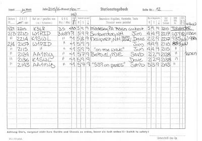
I spent most of a week working to raise the RF output power from my unijunction transmitter to nearly 1mW. I was rewarded this evening with two contacts.

Jim/W1PID exchanged (599/449) signal reports with me from Sanbornton, NH (112km) at 2210z!

Dave/K1SWL did the same (589/229) from Newport, NH (95km) some four minutes later!

I should think these were the first-ever radio contacts made using a unijunction transistor as the transmitter.

FYI: my receiver was comprised of a single 1N34a germanium diode mixer followed by a single 2N35 germanium transistor audio amplifier. Great signals on this end.

Wikipedia on Unijunction Transistors: https://en.wikipedia.org/wiki/Unijunction_transistor

Wednesday, February 3, 2016

New VFO for the Frankenstein R2 Phasing Receiver


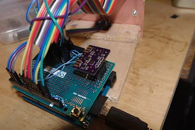
I've wanted to change the VFO in my R2 phasing receiver.  The AD9850 DDS VFO with a divide by 4  I-Q generator limited me to 160, 80 and 40 meters.  But an Si5351 chip will go up to 160 MHz.  With a divide by 2 I-Q generator, this should allow me to cover 160 through 6 meters. I got the Arduino, LCD and rotary encoder all working tonight.  Thanks to Thomas LA3PNA for the code, and to Tom AK2B for help with the Arduino. The Si5351 board that you see sitting atop the Arduino is the work of Dean AC9JQ.  Thanks Dean.  

The flip-flop and inverter IC's should arrive this week.  That will allow me to finish up this VFO conversion project.

Sunday, January 31, 2016

Dead Chickens and Fake Transistors in Medellin Colombia: HK4DEI's Micro 40 DSB Rig


Daniel HK4DEI wrote to report that page 149 of the SolderSmoke book was providing some solace and comfort as he struggled to get his version of Peter Parker's Micro 40 Double Sideband rig going.  He was having problems with the amplifier.   He was almost at the point of sacrificing chickens to Papa Legba.  I wished him luck and told him to hang in there. 

Elisa saw my e-mail to Daniel and complained that I hadn't given him the solution to his amplifier woes.  I tried to explain to her that there are sometimes things in this universe that are just UNKNOWABLE.  C.F. Rockey W9SCH (who alerted us in SPRAT 22 to the chicken sacrifice option) spoke of transistors that exhibit "quantum mechanical necromancy."  Rockey explained that when this happens, "The transistor simply turns up its toes and dies. Not even an Atomic Physicist can tell you why!"  


But Daniel persisted.  And he won the battle:

Hey Bill
Did you kill some chickens already? If you did, THANK YOU!  If you don't, then please enjoy a nice sancocho de gallina for me.

But seriously... guess what?
FAKE TRANSISTORS!!!!
I knew I couldn't be screwing everything up so badly and VK3YE's circuit couldn't be so wrong.
I was getting nuts trying to understand why it wasn't working, changing a single inductor could fry the final instantly or not getting any power out at all (?) also my final BD139 was getting extremely hot, and many of them died with no apparent reason (Page 149!!!!).
I ordered a "good" deal of BD139's and BD140's combo for an incredible low price from [A WEB SITE], I've ordered many *apparently good components from that site with no problems so far... mainly resistors and capacitors. Having tried everything to get my circuit working and after some quick online search about fake transistors from china my suspicions grew considerably and I remembered some -other- BD139's I had ordered from Amazon some time ago.
I proceeded to solder the new transistors in place in my PA and Bingo! No more heating of the final and about the expected 0.5W out from my first DSB homebrew rig. I quickly reported to a fellow homebrewer in a local net and the report was amazing! 59 +10, the final transistor was comfortably warm to the touch and my mind could finally rest... lesson learned! What an electromagnetic achievement!
Just wanted to share my success Bill and thank you again for you book and you kind response.
Please say hi to Elisa and the Cristalinhos from a fellow Latin friend.
Clear Skies.
73/72 from Colombia!
Daniel
HK4DEI


Saturday, January 30, 2016

RESISTANCE IS FUTILE! Diode Tunnels in Germany and Vermont

Peter DL3PB's Zinc Negative Resistance Transceiver

Michael Rainey AA1TJ's work with tunnel diode rigs has provided much grist for the SolderSmoke mill over the years, as has the tunneling of Peter DL3PB:
http://soldersmoke.blogspot.com/search?q=tunnel+diodes

They are back at it!

Michael updates Peter (and us!) us on his efforts of this week:

Grüss Peter!

A broadband measurement of my output power (using an AD8307 log-amp power meter) indicates 139uW. Spurious frequency energy accounts for 2uW, leaving 137uW at 3.552MHz. I believe this is roughly the output power produced by your ZnO transmitter? 

This morning I'll attempt to increase the unijunction (UJT) 80m RF output power by inserting a pair of back-to-back standard-recovery power supply rectifiers (1N5401-ish) at the  UJT base-2 to ground node. Thus far I have relied exclusively on internal UJT nonlinearity for the generation of harmonic energy. I've reason to believe the minority carrier charge-storage capability (normally a defect, but hopefully a virtue here!) of these rectifiers will efficiently produce a bipolar pulse-pair every 1/500kHz seconds resulting in an odd-order comb-spectrum. At least that's the plan...we'll see how it works out ;-)

Peter, I never heard the results of your ZnO DXpedition? Any luck OM?

Okay, I'm off to the Hobbit-Hole. My heartfelt thanks to you all for your shared interest in this cock-eyed project.

73,
Mike, AA1TJ       


Peter, DL3PB, in Germany respond with amazing news of his own.  Peter is homebrewing his own tunnel diodes, using Zinc Negative Resistance Oscillators.  No store-bought appliances for him!
At this point you really have to visit the pages of Nyle K7NS
and
Nyle tells of building a little microwatt transmitter, and, once the snow melted, climbing a hill 5 miles from town to see if he could hear it.  This reminded me of young Marconi's early efforts in Bologna.

Peter writes:

Hi Folks,

Mike, your plan on how to increase output-power sounds reasonable –  yes, a few dB could really help, to make reception a bit steadier and thus allow a QSO.

Well, I thought we had already talked about the ZnO TRX attempt, but obviously we didn’t. The reason is dead simple - It didn’t work.

[ The ZnO TRX is a minimalist 80m band transceiver with a homemade tunnel-detector-diode as the only active device –  based on Nyle’s K7NS experiments
http://sparkbangbuzz.com/zinc-osc-2/zinc-osc3.htm – please find attached an early schematic ]

Three days in a row after Xmas I tried for several hours each, I had announced the activity on QRPSPOTS and the German QRP Forum. Thus several guys
within the right distance were really trying hard to copy. I used different temporary antennas, mostly verticals, but also a sloper dipole - nada, niente , nothing.
One or two OMs reported weak CW signals on the scheduled QRG, but too deep in the noise, to even make out, whether it was me or someone else.

Yes, power is more or less comparable, actually it’s 0.5mW +/-3dB depending on the day’s form of the homemade tunnel-detector, but I guess all my antennas are
some dB behind a full-size dipole, so at the end it’s pretty much the same.

Folks were very cooperative during the test itself, but after it was clear, that it had not worked, the usual trolls showed up to explain, why that never could have worked...
I plan another test within the coming week e.g. during the PA-contest next weekend ( I’m only 30km from the dutch border ) with a base loaded 15m vertical –
be assured, you’re the first to hear about any success in terms of QSO or just being heard anywhere.

What would we go for, if everything works as expected and/or right from the beginning – or as Jim said it : What fun...
73!

Peter/DL3PB

Finally, Alan Wolke provides a very illuminating (as always) explanation of tunnel diodes):


Friday, January 29, 2016

AA1TJ's 150 Microwatts Heard at 112 Kilometers -- "To Boldly Go Where no Unijunction Has Gone Before."

AA1TJ reports: 

Breaking news from W1PID... "Mike! I just copied the beacon. I got 'VVV de AA1TJ 150 uw' and it faded out. 2146Z on 3551.95MHz" That's it! Jim copied a message produced by a lowly unijunction at a distance of 112km. How's that for cool! In a nutshell... the unijunction runs as an R-C relaxation oscillator at ~500kHz. A quartz crystal at the emitter frequency-locks the sawtooth waveform to 507kHz. The 7th harmonic is admitted to the antenna via a bandpass filter. The RF output to DC input conversion efficiency is all of 0.1%. Heat-sink? Check! Mission statement:
"...to boldly go where no unijunction has gone before."
Cheers,
Mike, AA1TJ


I think the really cool thing is that EM waves are once again flying out of the Vermont Hobbit Hole, propelled into space by the poet laureate of QRP.

Thursday, January 28, 2016

QST de AA1TJ -- Please listen for Mike's Microwatts!

QST de AA1TJ...

I've a 150uW transmitter built from a single unijunction transistor currently running as a beacon on 3552kHz. If my New England amateur radio pals would be so kind as take a listen for it I'd be most appreciative!

Alan Wolke W2AEW Builds a Michigan Mighty Mite (Video)


We are honored to induct Alan Wolke W2AEW into the Colorburst Liberation Army.  And for his valiant effort to build and explain a MMM Low-Pass filter, he is immediately promoted to the rank of CBLA Two Star General.  Congratulations General Wolke.

As is the case with all of  his videos, this one has already had an impact far and wide.  Ian writes from far-off Western Australia:

Wednesday, January 27, 2016

Humidity Data and the Zapping of my LCD Display

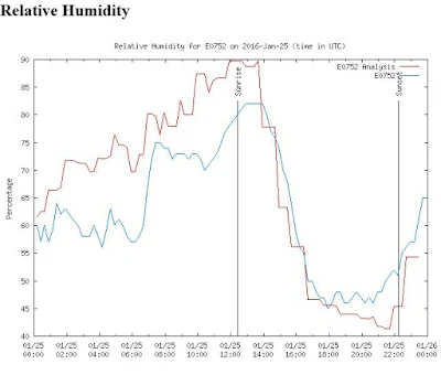
Sometimes the Radio Gods conspire against you.   Check out the chart above.  It shows relative humidity at my location.   I zapped my LCD display right around 2000 UTC on January 25, 2016.  That poor little LCD didn't stand a chance :-(

Right now relative humidity here is 79%.  No sparks now! 

I like the solution (!) proposed by Brendan, EI6IZ:

You can get an anti-static spray designed to treat carpet, upholstered furniture etc. This is a sensible thing to do if one tinkers with electronics and for the average hamshack a bottle will last for many years as it only needs to be applied lightly and infrequently.
For example
http://ie.rs-online.com/web/p/esd-safe-clean-room-treatments-lotions-dispensers/0182893/ For cheapskates however, diluted fabric softener sprayed on the carpet and chair will work well for at least a few months but will require much more frequent application than the 'proper stuff'.

I give my car seat an occasional squirt in dry summers to stop the 'zap' when getting out on a dry day.

73
Brendan EI6IZ


0.946L Anti-Static Liquid

Tuesday, January 26, 2016

An Electro-Static Bandaid to Protect Sensitive LCD Displays

After the big East Coast blizzard,  the atmosphere in my ham shack became very dry.  I sit in one of those desk chairs with little plastic wheels.  The shack is carpeted.  So when I roll from operating bench to workbench,  the chair, the carpet, the dry air and I all become a kind of Van de Graaff generator.  Yesterday, my hand brushed against the 16X2 LCD display on my new R2 phasing receiver.  The pretty glowing numerals in that display disappeared in a small spark, never to return.

I swapped out another display I had, so all is well.  But the repair was a pain in the neck, involving the soldering of some 16 LCD pins, so I don't want to do it again.  I consulted with Pete Juliano N6QW who told me that this kind of LCD carnage is quite common in dry environments.  He said he had cured the problem by placing a small piece of Plexiglas in front of his displays. 

This got me thinking about those static protective bags that Digikey uses when shipping many of its components.  Might the material from these bags prevent the loss of another display? 

I retrieved a couple of these bags from the garbage and did a little test:

First, I rolled across the shack in the chair with a small screw-driver in hand.   At the other end of the shack lies my well-grounded DX-100 transmitter.  I moved the screwdriver close to the metal on-off switch.  SPARK!  It was visible, and quite audible in the AM broadcast receiver nearby. 

Next I taped a small piece of this material over the switch and repeated the ride in the chair.  No spark. Nada.  I repeated this several times and always got the same result.

It appears that the material in the bag helps dissipated the static discharge over a wider area, preventing the spark.  I quickly taped a piece of this material over the two LCD screens in my shack.  It's not pretty, but it is temporary, and cheaper than a humidifier.

I'm not going to try this on the actual screens, but I do think these small pieces of material will help prevent another accidental frying of an LCD display.

Here is the Wiki on anti-static bags: https://en.wikipedia.org/wiki/Antistatic_bag

And here is the data sheet on the bags that I am using:
http://documents.staticcontrol.com/PDF/Static_Shielding_Bag_1000_Series.pdf

Monday, January 25, 2016

1936 Shortwave Listener QSL card


I found this today while rummaging around in the shack.  It is starting to fall apart so I figured I better digitize it before it turns into dust.

July 24, 1936.  7 am in Central Germany.  29.0 degrees Centigrade.  Clear skies?  German Shortwave Receiving Station DE 2518/F monitored W5AIR's contact with Irish station EI7F on 20 meter CW. The receiver was an OV2 Schnell tube (almost certainly a regen) fed by a 38.5 meter long antenna.  

Conditions must have been pretty good -- they were approaching the peak of sunspot cycle 17.

In 1954 W5AIR was assigned to Garold D. Sears.  He was probably the operator.

Sunday, January 24, 2016

Designer: Douglas Bowman | Dimodifikasi oleh Abdul Munir Original Posting Rounders 3 Column